NISSAN PATROL 2004 Electronic Repair Manual
PATROL 2004
NISSAN
NISSAN
https://www.carmanualsonline.info/img/5/57364/w960_57364-0.png
NISSAN PATROL 2004 Electronic Repair Manual
Trending: AUX, Td42, oil, charger, oil pressure, tire type, height adjustment
Page 481 of 579

Features (TB48 Engine Models)
CAN COMMUNICATION SYSTEM DESCRIPTION
CAN (Controller Area Network) is a serial communication line for real time application. It is an on-vehicle mul-
tiplex communication line with high data communication speed and excellent error detection ability. Many
electronic control units are equipped onto a vehicle, and each control unit shares information and links with
other control units during operation (not independent). In CAN communication, control units are connected with
2 communication lines (CAN H line, CAN L line) allowing a high rate of information transmission with less wir-
ing. Each control unit transmits/receives data but selectively reads required data only.
SYSTEM CONSTRUCTION
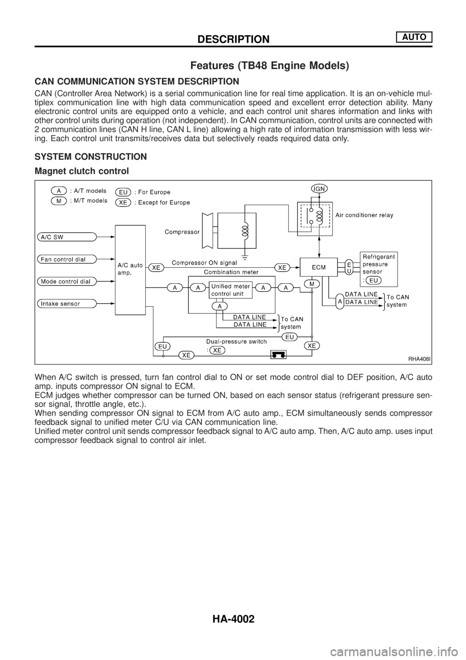
Magnet clutch control
When A/C switch is pressed, turn fan control dial to ON or set mode control dial to DEF position, A/C auto
amp. inputs compressor ON signal to ECM.
ECM judges whether compressor can be turned ON, based on each sensor status (refrigerant pressure sen-
sor signal, throttle angle, etc.).
When sending compressor ON signal to ECM from A/C auto amp., ECM simultaneously sends compressor
feedback signal to uni®ed meter C/U via CAN communication line.
Uni®ed meter control unit sends compressor feedback signal to A/C auto amp. Then, A/C auto amp. uses input
compressor feedback signal to control air inlet.
RHA408I
DESCRIPTIONAUTO
HA-4002
Page 482 of 579
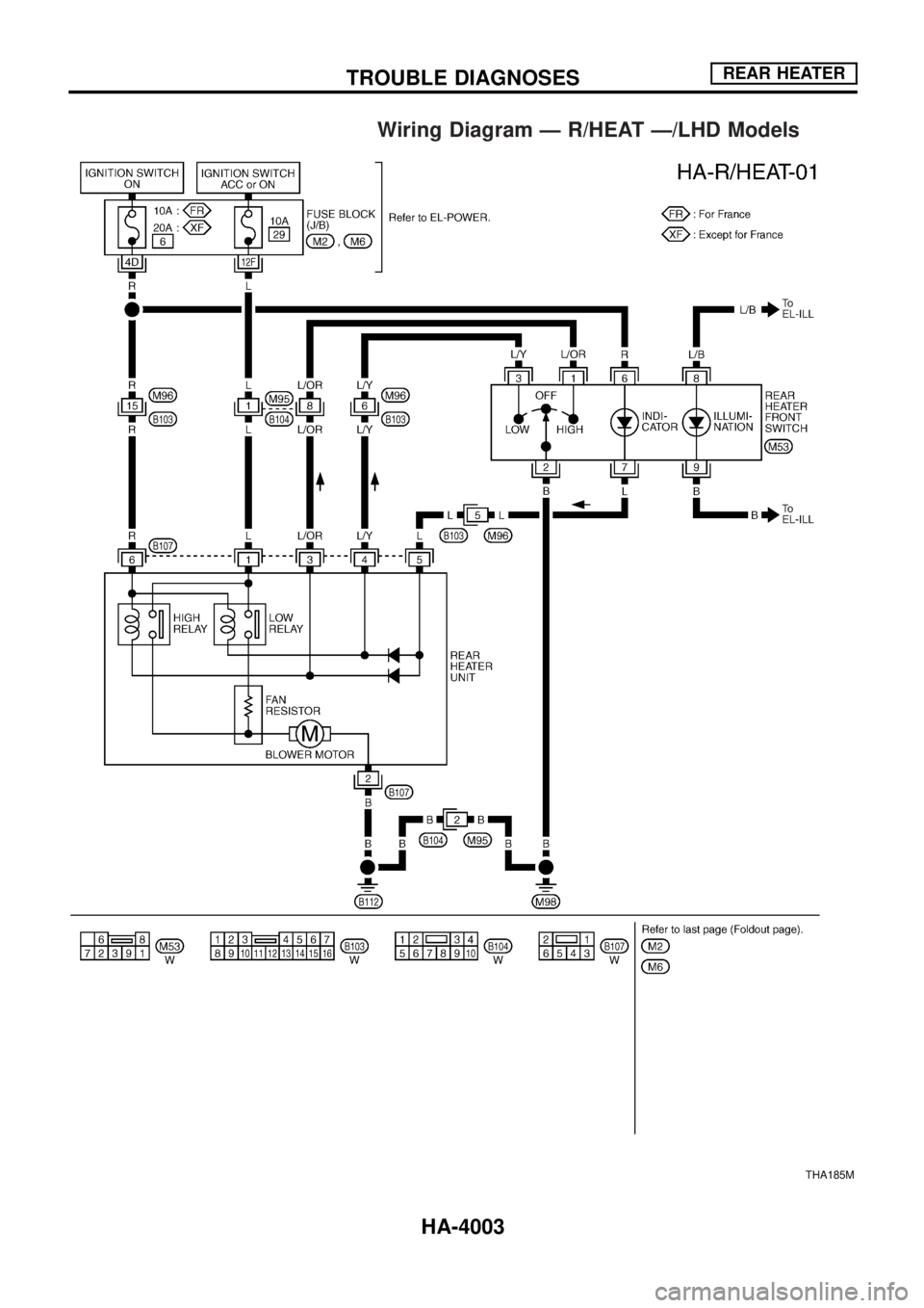
Wiring Diagram Ð R/HEAT Ð/LHD Models
THA185M
TROUBLE DIAGNOSESREAR HEATER
HA-4003
Page 483 of 579
Wiring Diagram Ð R/HEAT Ð/RHD Models
THA186M
TROUBLE DIAGNOSESREAR HEATER
HA-4004
Page 484 of 579
Wiring Diagram Ð A/C, M Ð/Wagon and
Hardtop Models with ZD Engine
THA187M
TROUBLE DIAGNOSESMANUAL
HA-4005
Page 485 of 579
THA188M
TROUBLE DIAGNOSESMANUAL
Wiring Diagram Ð A/C, M Ð/Wagon and
Hardtop Models with ZD Engine (Cont'd)
HA-4006
Page 486 of 579

Control Operation
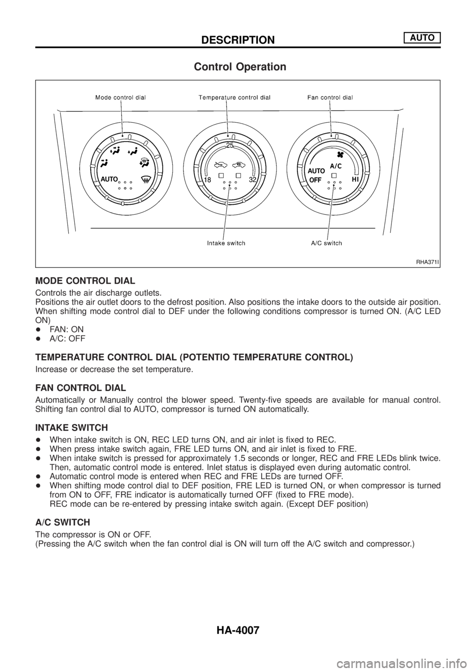
MODE CONTROL DIAL
Controls the air discharge outlets.
Positions the air outlet doors to the defrost position. Also positions the intake doors to the outside air position.
When shifting mode control dial to DEF under the following conditions compressor is turned ON. (A/C LED
ON)
+FAN: ON
+A/C: OFF
TEMPERATURE CONTROL DIAL (POTENTIO TEMPERATURE CONTROL)
Increase or decrease the set temperature.
FAN CONTROL DIAL
Automatically or Manually control the blower speed. Twenty-®ve speeds are available for manual control.
Shifting fan control dial to AUTO, compressor is turned ON automatically.
INTAKE SWITCH
+When intake switch is ON, REC LED turns ON, and air inlet is ®xed to REC.
+When press intake switch again, FRE LED turns ON, and air inlet is ®xed to FRE.
+When intake switch is pressed for approximately 1.5 seconds or longer, REC and FRE LEDs blink twice.
Then, automatic control mode is entered. Inlet status is displayed even during automatic control.
+Automatic control mode is entered when REC and FRE LEDs are turned OFF.
+When shifting mode control dial to DEF position, FRE LED is turned ON, or when compressor is turned
from ON to OFF, FRE indicator is automatically turned OFF (®xed to FRE mode).
REC mode can be re-entered by pressing intake switch again. (Except DEF position)
A/C SWITCH
The compressor is ON or OFF.
(Pressing the A/C switch when the fan control dial is ON will turn off the A/C switch and compressor.)
RHA371I
DESCRIPTIONAUTO
HA-4007
Page 487 of 579
Circuit Diagram Ð A/C, A Ð/TB48 Engine
THA189M
TROUBLE DIAGNOSESAUTO
HA-4008
Page 488 of 579
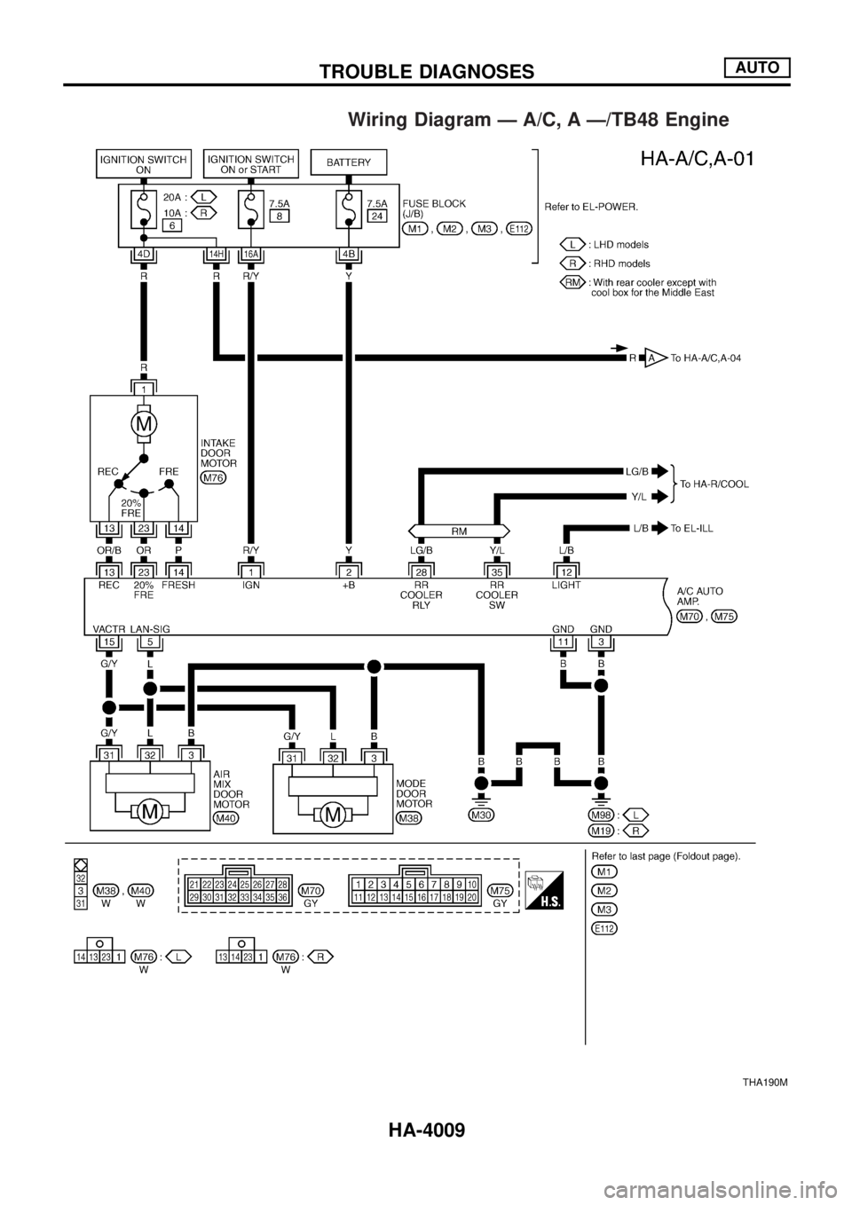
Wiring Diagram Ð A/C, A Ð/TB48 Engine
THA190M
TROUBLE DIAGNOSESAUTO
HA-4009
Page 489 of 579
THA191M
TROUBLE DIAGNOSESAUTO
Wiring Diagram Ð A/C, A Ð/TB48 Engine
(Cont'd)
HA-4010
Page 490 of 579
THA192M
TROUBLE DIAGNOSESAUTO
Wiring Diagram Ð A/C, A Ð/TB48 Engine
(Cont'd)
HA-4011
Trending: engine oil capacity, brake light, keyless entry, Ecm, air condition, wheel size, instrument panel


