NISSAN PATROL 2004 Electronic Repair Manual
Manufacturer: NISSAN, Model Year: 2004, Model line: PATROL, Model: NISSAN PATROL 2004Pages: 579, PDF Size: 26.61 MB
Page 451 of 579
Removal
1. Remove the following parts.
+Undercover
+Engine oil (Drain)
+Engine coolant (Drain)
+Engine cover
+Intercooler
+Air inlet pipe
+Air cleaner case
+Throttle body
+Swirl and intake air control valve control solenoid valve and
bracket
+Vacuum tank
+Glow plate
+Rocker cover
+Spill tube
+Radiator shrouds (Rear and Lower)
+Cooling fan
+Radiator hose (Upper and Lower)
+Auxiliary belt and auto tensioner.
2. Remove the alternator.
3. Remove the A/C compressor and bracket with piping con-
nected. Move and support it at the LH side of engine bay with
a rope to avoid putting load on piping.
Refer to HA section in NISSAN Service Manual (Publication No.
SM9E-Y61CG2 or SM9E-Y61CG3).
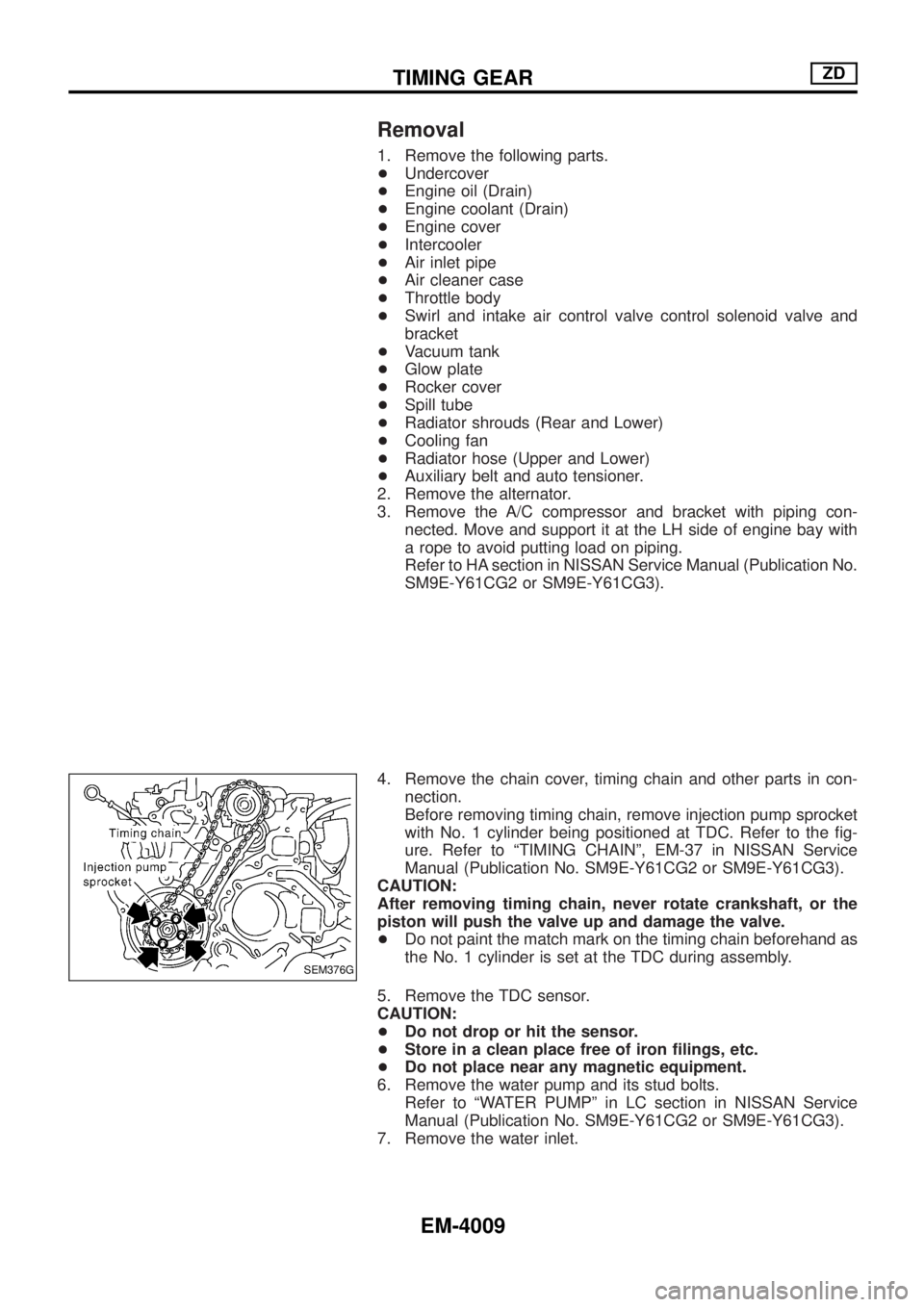
4. Remove the chain cover, timing chain and other parts in con-
nection.
Before removing timing chain, remove injection pump sprocket
with No. 1 cylinder being positioned at TDC. Refer to the ®g-
ure. Refer to ªTIMING CHAINº, EM-37 in NISSAN Service
Manual (Publication No. SM9E-Y61CG2 or SM9E-Y61CG3).
CAUTION:
After removing timing chain, never rotate crankshaft, or the
piston will push the valve up and damage the valve.
+Do not paint the match mark on the timing chain beforehand as
the No. 1 cylinder is set at the TDC during assembly.
5. Remove the TDC sensor.
CAUTION:
+Do not drop or hit the sensor.
+Store in a clean place free of iron ®lings, etc.
+Do not place near any magnetic equipment.
6. Remove the water pump and its stud bolts.
Refer to ªWATER PUMPº in LC section in NISSAN Service
Manual (Publication No. SM9E-Y61CG2 or SM9E-Y61CG3).
7. Remove the water inlet.
SEM376G
TIMING GEARZD
EM-4009
Page 452 of 579
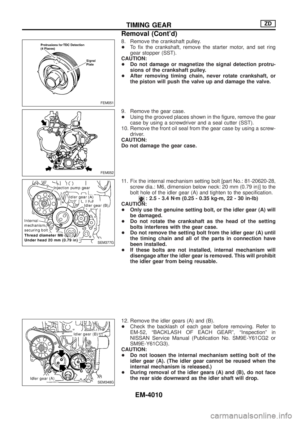
8. Remove the crankshaft pulley.
+To ®x the crankshaft, remove the starter motor, and set ring
gear stopper (SST).
CAUTION:
+Do not damage or magnetize the signal detection protru-
sions of the crankshaft pulley.
+After removing timing chain, never rotate crankshaft, or
the piston will push the valve up and damage the valve.
9. Remove the gear case.
+Using the grooved places shown in the ®gure, remove the gear
case by using a screwdriver and a seal cutter (SST).
10. Remove the front oil seal from the gear case by using a screw-
driver.
CAUTION:
Do not damage the gear case.
11. Fix the internal mechanism setting bolt [part No.: 81-20620-28,
screw dia.: M6, dimension below neck: 20 mm (0.79 in)] to the
bolt hole of the idler gear (A) and tighten to the speci®cation.
: 2.5 - 3.4 Nzm (0.25 - 0.35 kg-m, 22 - 30 in-lb)
CAUTION:
+Only use the genuine setting bolt, or the idler gear (A) will
be damaged.
+Do not rotate the crankshaft as the head of the setting
bolts interferes with the gear case.
+Do not remove the setting bolt from the idler gear (A) until
the timing chain and all of the parts in connection have
been installed.
+If these bolts are not installed, internal mechanism will
disengage after the idler gear is removed. This will prohibit
the idler gear from being reusable.
12. Remove the idler gears (A) and (B).
+Check the backlash of each gear before removing. Refer to
EM-52, ªBACKLASH OF EACH GEARº, ªInspectionº in
NISSAN Service Manual (Publication No. SM9E-Y61CG2 or
SM9E-Y61CG3).
CAUTION:
+Do not loosen the internal mechanism setting bolt of the
idler gear (A). (The idler gear cannot be reused when the
internal mechanism is released.)
+During removal of the idler gears (A) and (B), do not face
the rear side downward as the idler shaft will drop.
FEM051
FEM052
SEM377G
SEM348G
TIMING GEARZD
Removal (Cont'd)
EM-4010
Page 453 of 579
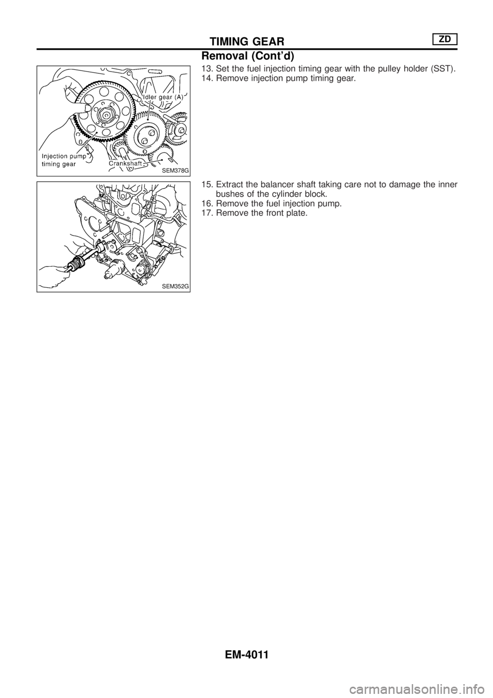
13. Set the fuel injection timing gear with the pulley holder (SST).
14. Remove injection pump timing gear.
15. Extract the balancer shaft taking care not to damage the inner
bushes of the cylinder block.
16. Remove the fuel injection pump.
17. Remove the front plate.
SEM378G
SEM352G
TIMING GEARZD
Removal (Cont'd)
EM-4011
Page 454 of 579
Installation
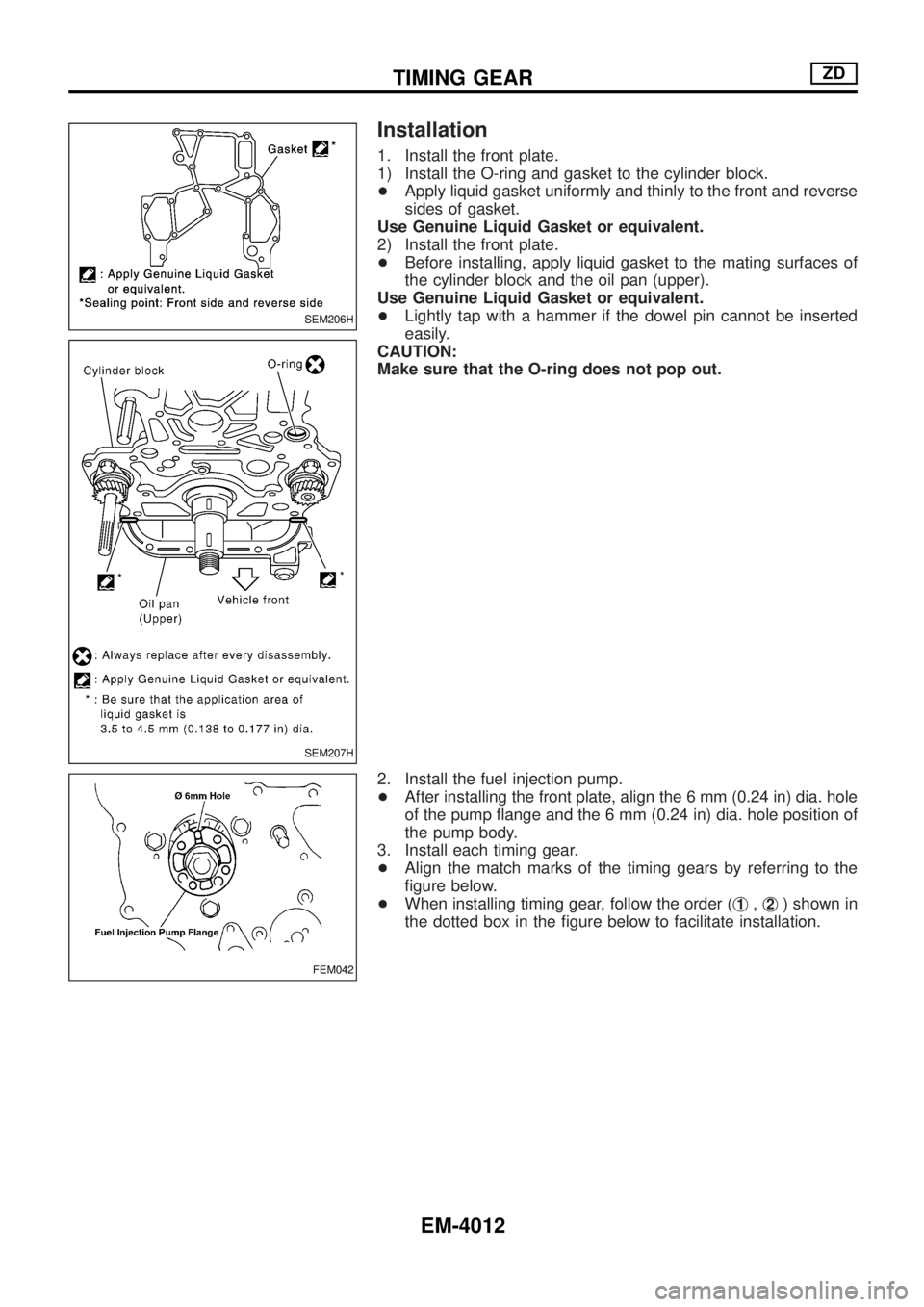
1. Install the front plate.
1) Install the O-ring and gasket to the cylinder block.
+Apply liquid gasket uniformly and thinly to the front and reverse
sides of gasket.
Use Genuine Liquid Gasket or equivalent.
2) Install the front plate.
+Before installing, apply liquid gasket to the mating surfaces of
the cylinder block and the oil pan (upper).
Use Genuine Liquid Gasket or equivalent.
+Lightly tap with a hammer if the dowel pin cannot be inserted
easily.
CAUTION:
Make sure that the O-ring does not pop out.
2. Install the fuel injection pump.
+After installing the front plate, align the 6 mm (0.24 in) dia. hole
of the pump ¯ange and the 6 mm (0.24 in) dia. hole position of
the pump body.
3. Install each timing gear.
+Align the match marks of the timing gears by referring to the
®gure below.
+When installing timing gear, follow the order (j
1,j2) shown in
the dotted box in the ®gure below to facilitate installation.
SEM206H
SEM207H
FEM042
TIMING GEARZD
EM-4012
Page 455 of 579
![NISSAN PATROL 2004 Electronic Repair Manual 4. Install the front oil seal to the gear case.
+Apply engine oil to the ®tting side.
+Evenly insert the front oil seal using a drift [outer dia.: approx.
64 mm (2.52 in)] completely.
CAUTION:
Make s NISSAN PATROL 2004 Electronic Repair Manual 4. Install the front oil seal to the gear case.
+Apply engine oil to the ®tting side.
+Evenly insert the front oil seal using a drift [outer dia.: approx.
64 mm (2.52 in)] completely.
CAUTION:
Make s](/img/5/57364/w960_57364-454.png)
4. Install the front oil seal to the gear case.
+Apply engine oil to the ®tting side.
+Evenly insert the front oil seal using a drift [outer dia.: approx.
64 mm (2.52 in)] completely.
CAUTION:
Make sure the oil seal does not spill off the end side of the gear
case.
5. Install the gear case.
1) Before installing gear case, remove all traces of liquid gasket
from mating surface using a scraper.
2) Align gasket with dowel and install.
FEM043
FEM044
SEM353G
TIMING GEARZD
Installation (Cont'd)
EM-4013
Page 456 of 579
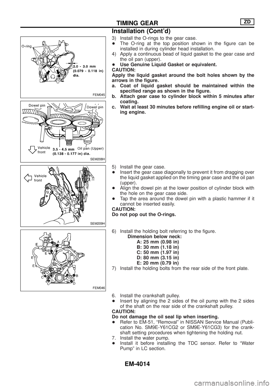
3) Install the O-rings to the gear case.
+The O-ring at the top position shown in the ®gure can be
installed in during cylinder head installation.
4) Apply a continuous bead of liquid gasket to the gear case and
the oil pan (upper).
+Use Genuine Liquid Gasket or equivalent.
CAUTION:
Apply the liquid gasket around the bolt holes shown by the
arrows in the ®gure.
a. Coat of liquid gasket should be maintained within the
speci®ed range as shown in the ®gure.
b. Attach gear case to cylinder block within 5 minutes after
coating.
c. Wait at least 30 minutes before re®lling engine oil or start-
ing engine.
5) Install the gear case.
+Insert the gear case diagonally to prevent it from dragging over
the liquid gasket applied on the timing gear case and the oil pan
(upper).
+Align the dowel pin at the lower position of cylinder block with
the hole on the gear case side.
+Tap the area around the dowel pin with a plastic hammer if it
cannot be inserted easily.
CAUTION:
Do not pop out the O-rings.
6) Install the holding bolt referring to the ®gure.
Dimension below neck:
A: 25 mm (0.98 in)
B: 30 mm (1.18 in)
C: 50 mm (1.97 in)
D: 80 mm (3.15 in)
E: 20 mm (0.79 in)
7) Install the holding bolts from the rear side of the front plate.
6. Install the crankshaft pulley.
+Insert by aligning the 2 sides of the oil pump with the 2 sides
of the shaft on the rear side of the crankshaft pulley.
CAUTION:
Do not damage the oil seal lip when inserting.
+Refer to EM-51, ªRemovalº in NISSAN Service Manual (Publi-
cation No. SM9E-Y61CG2 or SM9E-Y61CG3) for the crank-
shaft setting procedures when tightening the holding nut.
7. Install the water pump.
+Install it before installing the TDC sensor. Refer to ªWater
Pumpº in LC section.
FEM045
SEM208H
SEM209H
FEM046
TIMING GEARZD
Installation (Cont'd)
EM-4014
Page 457 of 579
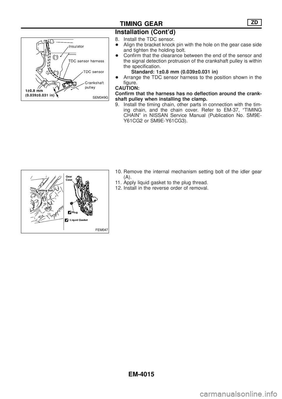
8. Install the TDC sensor.
+Align the bracket knock pin with the hole on the gear case side
and tighten the holding bolt.
+Con®rm that the clearance between the end of the sensor and
the signal detection protrusion of the crankshaft pulley is within
the speci®cation.
Standard: 1 0.8 mm (0.039 0.031 in)
+Arrange the TDC sensor harness to the position shown in the
®gure.
CAUTION:
Con®rm that the harness has no de¯ection around the crank-
shaft pulley when installing the clamp.
9. Install the timing chain, other parts in connection with the tim-
ing chain, and the chain cover. Refer to EM-37, ªTIMING
CHAINº in NISSAN Service Manual (Publication No. SM9E-
Y61CG2 or SM9E-Y61CG3).
10. Remove the internal mechanism setting bolt of the idler gear
(A).
11. Apply liquid gasket to the plug thread.
12. Install in the reverse order of removal.
SEM349G
FEM047
TIMING GEARZD
Installation (Cont'd)
EM-4015
Page 458 of 579

Disassembly and Assembly
FEM081A
CYLINDER HEADZD
EM-4016
Page 459 of 579
Valve
VALVE CLEARANCE
Unit: mm (in)
ItemsCold*
Intake and exhaust0.30 - 0.40 (0.012 - 0.016)
*: Approximately 20ÉC (68ÉF)
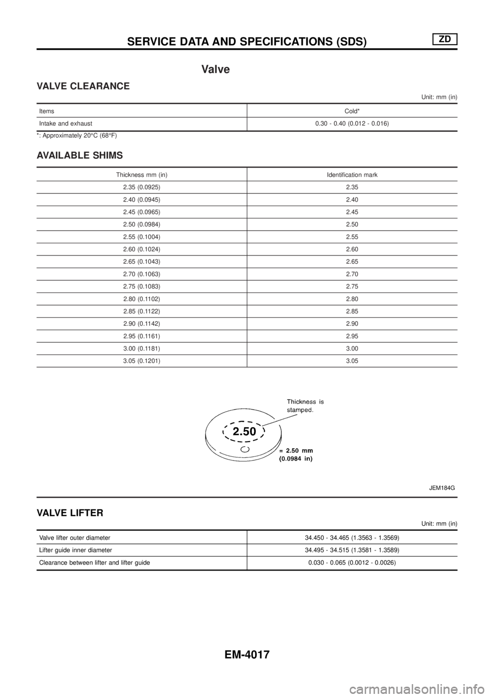
AVAILABLE SHIMS
Thickness mm (in) Identi®cation mark
2.35 (0.0925) 2.35
2.40 (0.0945) 2.40
2.45 (0.0965) 2.45
2.50 (0.0984) 2.50
2.55 (0.1004) 2.55
2.60 (0.1024) 2.60
2.65 (0.1043) 2.65
2.70 (0.1063) 2.70
2.75 (0.1083) 2.75
2.80 (0.1102) 2.80
2.85 (0.1122) 2.85
2.90 (0.1142) 2.90
2.95 (0.1161) 2.95
3.00 (0.1181) 3.00
3.05 (0.1201) 3.05
JEM184G
VALVE LIFTER
Unit: mm (in)
Valve lifter outer diameter 34.450 - 34.465 (1.3563 - 1.3569)
Lifter guide inner diameter 34.495 - 34.515 (1.3581 - 1.3589)
Clearance between lifter and lifter guide 0.030 - 0.065 (0.0012 - 0.0026)
SERVICE DATA AND SPECIFICATIONS (SDS)ZD
EM-4017
Page 460 of 579
EXHAUST SYSTEMS
SECTION
FE
MODIFICATION NOTICE:
+ Wiring diagram of sub fuel tank control system has been modi®ed.
CONTENTS
TROUBLE DIAGNOSES ...........................................4002
Self-diagnosis for Sub Fuel Tank Control Module.4002
Circuit Diagram Ð S/TANK Ð ..............................4003 Wiring Diagram Ð S/TANK Ð ..............................4004
EXHAUST SYSTEM ..................................................4008
FE-4001