NISSAN PATROL 2004 Electronic Repair Manual
PATROL 2004
NISSAN
NISSAN
https://www.carmanualsonline.info/img/5/57364/w960_57364-0.png
NISSAN PATROL 2004 Electronic Repair Manual
Trending: fuses, diagram, battery location, engine oil, audio, General information, service
Page 511 of 579
Operational Check
The purpose of the operational check is to con®rm that the system
is as it should be. The systems which will be checked are the
blower, mode (discharge air), intake air, temperature decrease,
temperature increase and A/C switch.
CONDITIONS:
+Engine running and at normal operating temperature.
PROCEDURE:
1. Check blower
1) Turn fan control dial to 1st speed. Blower should operate at low
speed.
2) Turn fan control dial to 2nd speed, and continue checking
blower speed until all speeds are checked.
3) Leave blower on MAX speed.
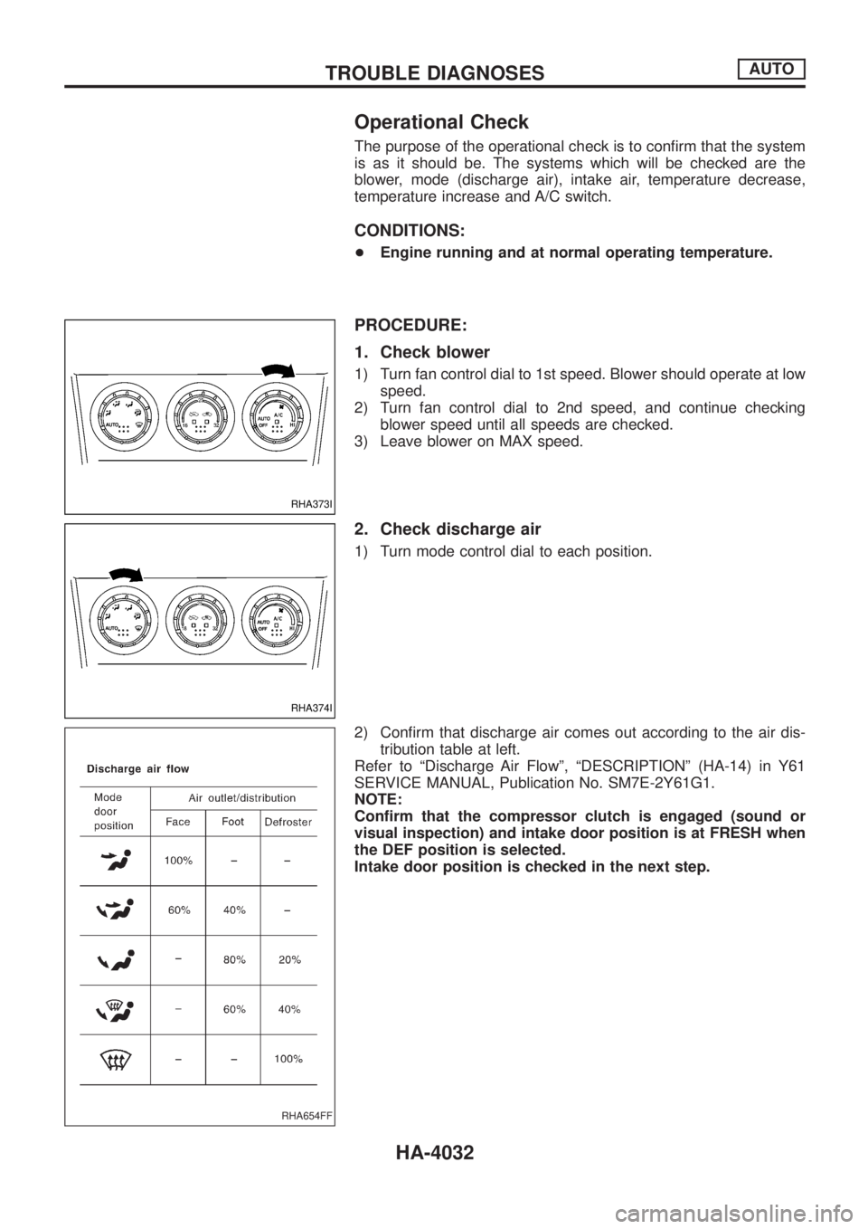
2. Check discharge air
1) Turn mode control dial to each position.
2) Con®rm that discharge air comes out according to the air dis-
tribution table at left.
Refer to ªDischarge Air Flowº, ªDESCRIPTIONº (HA-14) in Y61
SERVICE MANUAL, Publication No. SM7E-2Y61G1.
NOTE:
Con®rm that the compressor clutch is engaged (sound or
visual inspection) and intake door position is at FRESH when
the DEF position is selected.
Intake door position is checked in the next step.
RHA373I
RHA374I
RHA654FF
TROUBLE DIAGNOSESAUTO
HA-4032
Page 512 of 579
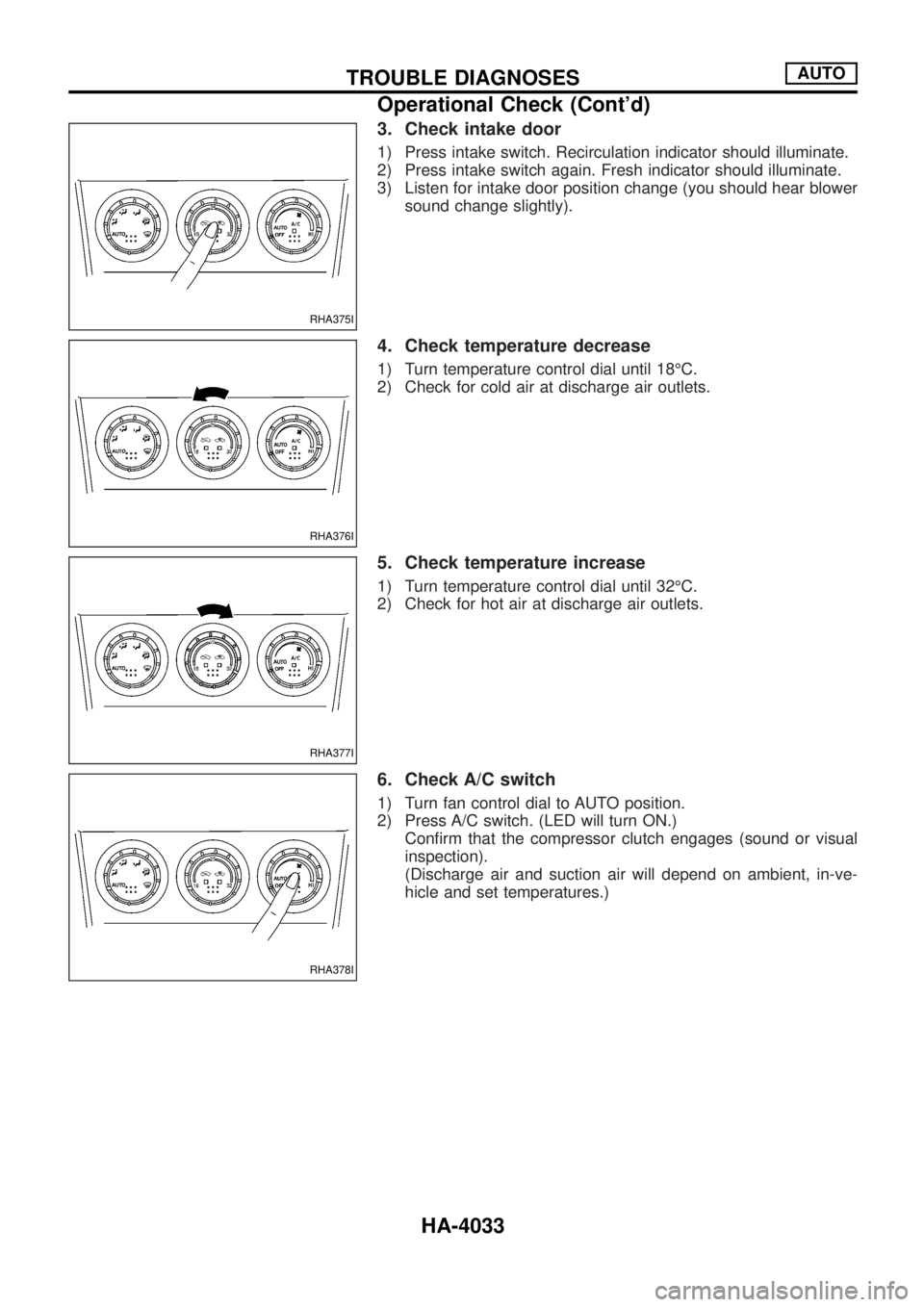
3. Check intake door
1) Press intake switch. Recirculation indicator should illuminate.
2) Press intake switch again. Fresh indicator should illuminate.
3) Listen for intake door position change (you should hear blower
sound change slightly).
4. Check temperature decrease
1) Turn temperature control dial until 18ÉC.
2) Check for cold air at discharge air outlets.
5. Check temperature increase
1) Turn temperature control dial until 32ÉC.
2) Check for hot air at discharge air outlets.
6. Check A/C switch
1) Turn fan control dial to AUTO position.
2) Press A/C switch. (LED will turn ON.)
Con®rm that the compressor clutch engages (sound or visual
inspection).
(Discharge air and suction air will depend on ambient, in-ve-
hicle and set temperatures.)
RHA375I
RHA376I
RHA377I
RHA378I
TROUBLE DIAGNOSESAUTO
Operational Check (Cont'd)
HA-4033
Page 513 of 579
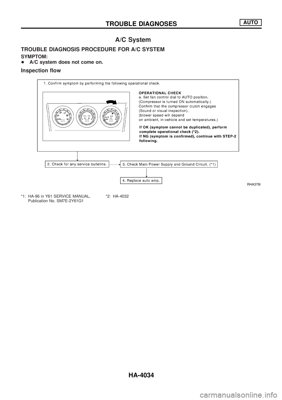
A/C System
TROUBLE DIAGNOSIS PROCEDURE FOR A/C SYSTEM
SYMPTOM:
+A/C system does not come on.
Inspection ¯ow
*1: HA-96 in Y61 SERVICE MANUAL,
Publication No. SM7E-2Y61G1*2: HA-4032
RHA379I
TROUBLE DIAGNOSESAUTO
HA-4034
Page 514 of 579
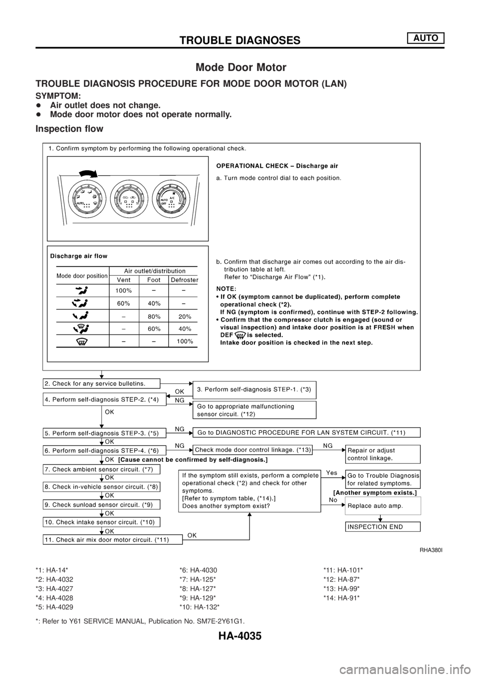
Mode Door Motor
TROUBLE DIAGNOSIS PROCEDURE FOR MODE DOOR MOTOR (LAN)
SYMPTOM:
+Air outlet does not change.
+Mode door motor does not operate normally.
Inspection ¯ow
*1: HA-14*
*2: HA-4032
*3: HA-4027
*4: HA-4028
*5: HA-4029*6: HA-4030
*7: HA-125*
*8: HA-127*
*9: HA-129*
*10: HA-132**11: HA-101*
*12: HA-87*
*13: HA-99*
*14: HA-91*
*: Refer to Y61 SERVICE MANUAL, Publication No. SM7E-2Y61G1.
RHA380I
TROUBLE DIAGNOSESAUTO
HA-4035
Page 515 of 579
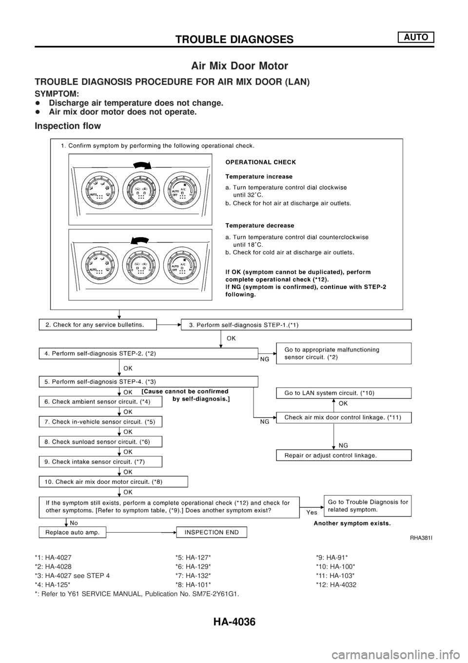
Air Mix Door Motor
TROUBLE DIAGNOSIS PROCEDURE FOR AIR MIX DOOR (LAN)
SYMPTOM:
+Discharge air temperature does not change.
+Air mix door motor does not operate.
Inspection ¯ow
*1: HA-4027
*2: HA-4028
*3: HA-4027 see STEP 4
*4: HA-125**5: HA-127*
*6: HA-129*
*7: HA-132*
*8: HA-101**9: HA-91*
*10: HA-100*
*11: HA-103*
*12: HA-4032
*: Refer to Y61 SERVICE MANUAL, Publication No. SM7E-2Y61G1.
RHA381I
TROUBLE DIAGNOSESAUTO
HA-4036
Page 516 of 579
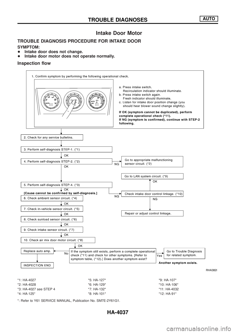
Intake Door Motor
TROUBLE DIAGNOSIS PROCEDURE FOR INTAKE DOOR
SYMPTOM:
+Intake door does not change.
+Intake door motor does not operate normally.
Inspection ¯ow
*1: HA-4027
*2: HA-4028
*3: HA-4027 see STEP 4
*4: HA-125**5: HA-127*
*6: HA-129*
*7: HA-132*
*8: HA-101**9: HA-107*
*10: HA-106*
*11: HA-4032
*12: HA-91*
*: Refer to Y61 SERVICE MANUAL, Publication No. SM7E-2Y61G1.
RHA382I
TROUBLE DIAGNOSESAUTO
HA-4037
Page 517 of 579
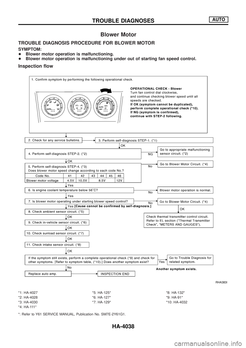
Blower Motor
TROUBLE DIAGNOSIS PROCEDURE FOR BLOWER MOTOR
SYMPTOM:
+Blower motor operation is malfunctioning.
+Blower motor operation is malfunctioning under out of starting fan speed control.
Inspection ¯ow
*1: HA-4027
*2: HA-4028
*3: HA-4030
*4: HA-111**5: HA-125*
*6: HA-127*
*7: HA-129**8: HA-132*
*9: HA-91*
*10: HA-4032
*: Refer to Y61 SERVICE MANUAL, Publication No. SM7E-2Y61G1.
RHA383I
TROUBLE DIAGNOSESAUTO
HA-4038
Page 518 of 579
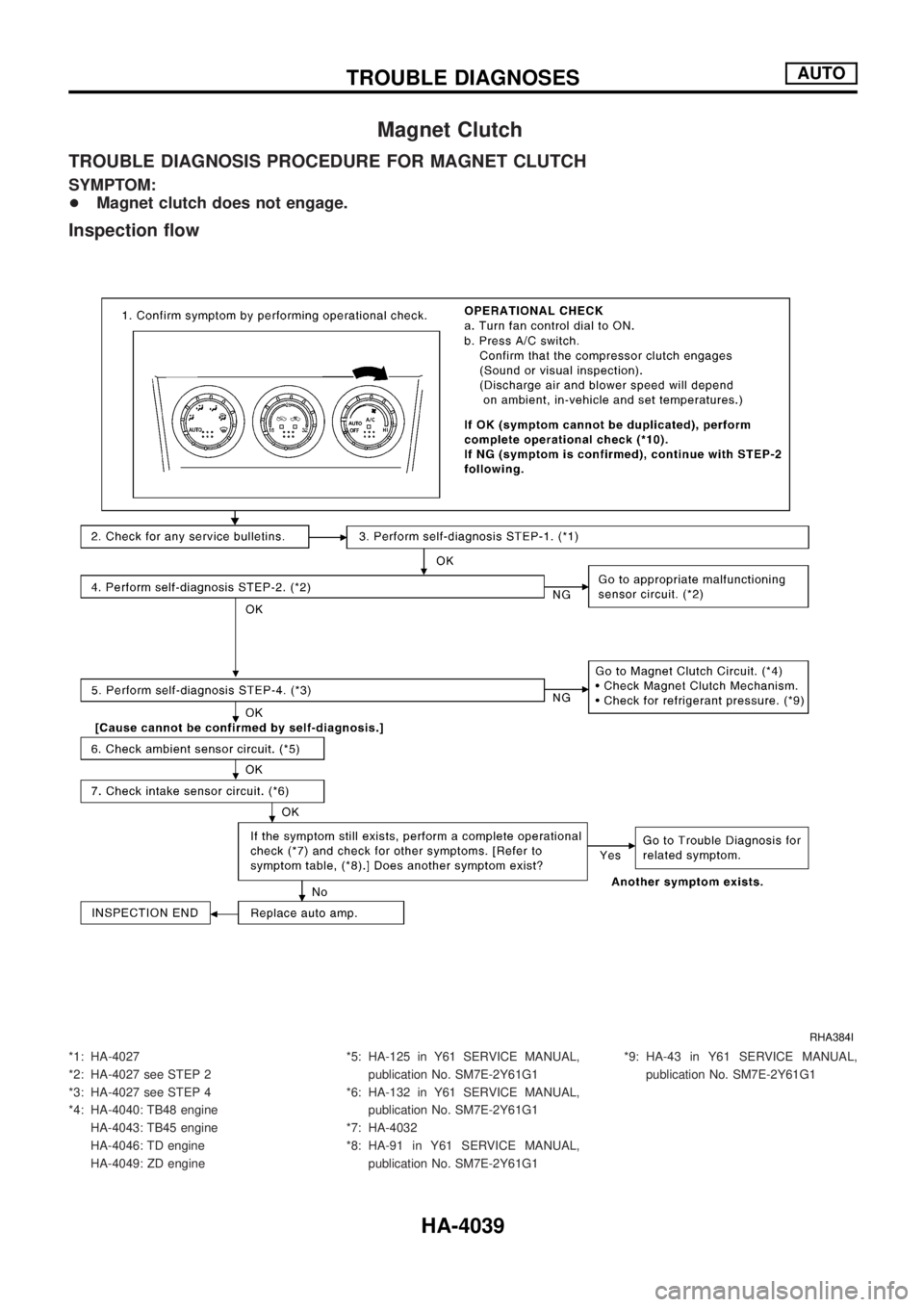
Magnet Clutch
TROUBLE DIAGNOSIS PROCEDURE FOR MAGNET CLUTCH
SYMPTOM:
+Magnet clutch does not engage.
Inspection ¯ow
*1: HA-4027
*2: HA-4027 see STEP 2
*3: HA-4027 see STEP 4
*4: HA-4040: TB48 engine
HA-4043: TB45 engine
HA-4046: TD engine
HA-4049: ZD engine*5: HA-125 in Y61 SERVICE MANUAL,
publication No. SM7E-2Y61G1
*6: HA-132 in Y61 SERVICE MANUAL,
publication No. SM7E-2Y61G1
*7: HA-4032
*8: HA-91 in Y61 SERVICE MANUAL,
publication No. SM7E-2Y61G1*9: HA-43 in Y61 SERVICE MANUAL,
publication No. SM7E-2Y61G1
RHA384I
TROUBLE DIAGNOSESAUTO
HA-4039
Page 519 of 579
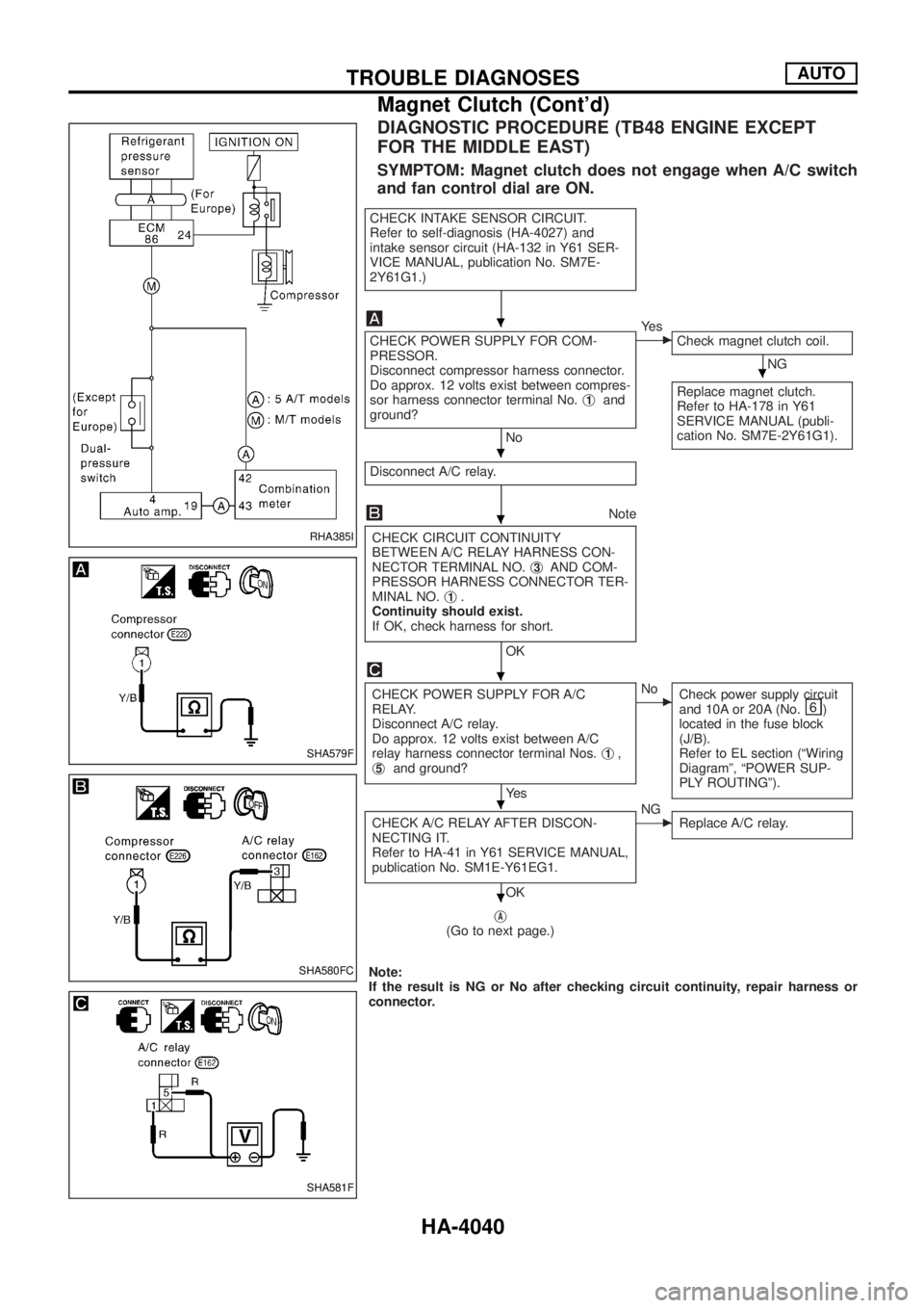
DIAGNOSTIC PROCEDURE (TB48 ENGINE EXCEPT
FOR THE MIDDLE EAST)
SYMPTOM: Magnet clutch does not engage when A/C switch
and fan control dial are ON.
CHECK INTAKE SENSOR CIRCUIT.
Refer to self-diagnosis (HA-4027) and
intake sensor circuit (HA-132 in Y61 SER-
VICE MANUAL, publication No. SM7E-
2Y61G1.)
CHECK POWER SUPPLY FOR COM-
PRESSOR.
Disconnect compressor harness connector.
Do approx. 12 volts exist between compres-
sor harness connector terminal No.j
1and
ground?
No
cYe s
Check magnet clutch coil.
NG
Replace magnet clutch.
Refer to HA-178 in Y61
SERVICE MANUAL (publi-
cation No. SM7E-2Y61G1).
Disconnect A/C relay.
Note
CHECK CIRCUIT CONTINUITY
BETWEEN A/C RELAY HARNESS CON-
NECTOR TERMINAL NO.j
3AND COM-
PRESSOR HARNESS CONNECTOR TER-
MINAL NO.j
1.
Continuity should exist.
If OK, check harness for short.
OK
CHECK POWER SUPPLY FOR A/C
RELAY.
Disconnect A/C relay.
Do approx. 12 volts exist between A/C
relay harness connector terminal Nos.j
1,
j5and ground?
Ye s
cNo
Check power supply circuit
and 10A or 20A (No.
)
located in the fuse block
(J/B).
Refer to EL section (ªWiring
Diagramº, ªPOWER SUP-
PLY ROUTINGº).
CHECK A/C RELAY AFTER DISCON-
NECTING IT.
Refer to HA-41 in Y61 SERVICE MANUAL,
publication No. SM1E-Y61EG1.
OK
cNG
Replace A/C relay.
jA(Go to next page.)
Note:
If the result is NG or No after checking circuit continuity, repair harness or
connector.
RHA385I
SHA579F
SHA580FC
SHA581F
.
.
.
.
.
.
.
TROUBLE DIAGNOSESAUTO
Magnet Clutch (Cont'd)
HA-4040
Page 520 of 579
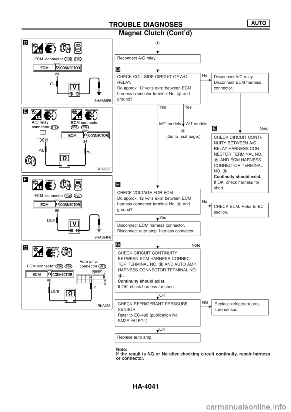
jA
Reconnect A/C relay.
CHECK COIL SIDE CIRCUIT OF A/C
RELAY.
Do approx. 12 volts exist between ECM
harness connector terminal No.j
24and
ground?
Ye s
Ye s
cNo
Disconnect A/C relay.
Disconnect ECM harness
connector.
jB
(Go to next page.)
Note
CHECK CIRCUIT CONTI-
NUITY BETWEEN A/C
RELAY HARNESS CON-
NECTOR TERMINAL NO.
j
2AND ECM HARNESS
CONNECTOR TERMINAL
NO.j
24.
Continuity should exist.
If OK, check harness for
short.
M/T models A/T models
CHECK VOLTAGE FOR ECM.
Do approx. 12 volts exist between ECM
harness connector terminal No.j
86and
ground?
Ye s
cNo
CHECK ECM. Refer to EC
section.
Disconnect ECM harness connector.
Disconnect auto amp. harness connector.
Note
CHECK CIRCUIT CONTINUITY
BETWEEN ECM HARNESS CONNEC-
TOR TERMINAL NO.j
86AND AUTO AMP.
HARNESS CONNECTOR TERMINAL NO.
j
4.
Continuity should exist.
If OK, check harness for short.
OK
CHECK REFRIGERANT PRESSURE
SENSOR.
Refer to EC-498 (publication No.
SM2E-Y61FG1).
OK
cNG
Replace refrigerant pres-
sure sensor.
Replace auto amp.
Note:
If the result is NG or No after checking circuit continuity, repair harness
or connector.
SHA582FB
SHA583F
SHA584FB
RHA386I
.
.
.
.
.
.
.
.
.
TROUBLE DIAGNOSESAUTO
Magnet Clutch (Cont'd)
HA-4041
Trending: engine control, remote control, Wir conditioner, key, spare tire, radiator, ECM DIAGRAM

