NISSAN PATROL 2004 Electronic Repair Manual
PATROL 2004
NISSAN
NISSAN
https://www.carmanualsonline.info/img/5/57364/w960_57364-0.png
NISSAN PATROL 2004 Electronic Repair Manual
Trending: display, ad blue, navigation update, mileage, fuse box, Combination, navigation system
Page 501 of 579
Wiring Diagram Ð A/C, A Ð/ZD Engine
THA203M
TROUBLE DIAGNOSESAUTO
HA-4022
Page 502 of 579
THA204M
TROUBLE DIAGNOSESAUTO
Wiring Diagram Ð A/C, A Ð/ZD Engine (Cont'd)
HA-4023
Page 503 of 579
THA205M
TROUBLE DIAGNOSESAUTO
Wiring Diagram Ð A/C, A Ð/ZD Engine (Cont'd)
HA-4024
Page 504 of 579
Self-diagnosis
INTRODUCTION AND GENERAL DESCRIPTION
The self-diagnostic system diagnoses sensors, door motors, blower motor, etc. by system line.
Self-diagnosis is step-1 to 7. There are two ways of changing method during self-diagnosis.
+Switching to self-diagnosis step-1 to 4.
Shifting from usual control to the self-diagnostic system is accomplished by starting the engine (turning
the ignition switch from OFF to ON) and pressing A/C switch for at least 5 seconds. The A/C switch must
be pressed within 10 seconds after starting the engine (ignition switch is turned ON). This system will be
canceled by either pressing intake switch or turning the ignition switch OFF. Shifting from one step to
another is accomplished be means of turning fan control dial, as required.
+Switching to self-diagnosis step-5 to 7 (Auxiliary mechanism).
Shifting from usual control to the self-diagnostic system is accomplished by starting the engine (turning
the ignition switch from OFF to ON) and pressing intake switch for at least 5 seconds. The intake switch
must be pressed within 10 seconds after starting the engine (ignition switch is turned ON). This system
will be canceled by either pressing A/C switch or turning the ignition switch OFF. Shifting from one step
to another is accomplished by means of turning fan control dial, as required.
TROUBLE DIAGNOSESAUTO
HA-4025
Page 505 of 579
CAUTION:
This A/C system cannot perform the setup of the FOOT position (Self-diagnosis: STEP-6).
LED of A/C switch illuminates. It means that it is ®xed to the initial setting.
RJIA2106E
TROUBLE DIAGNOSESAUTO
Self-diagnosis (Cont'd)
HA-4026
Page 506 of 579
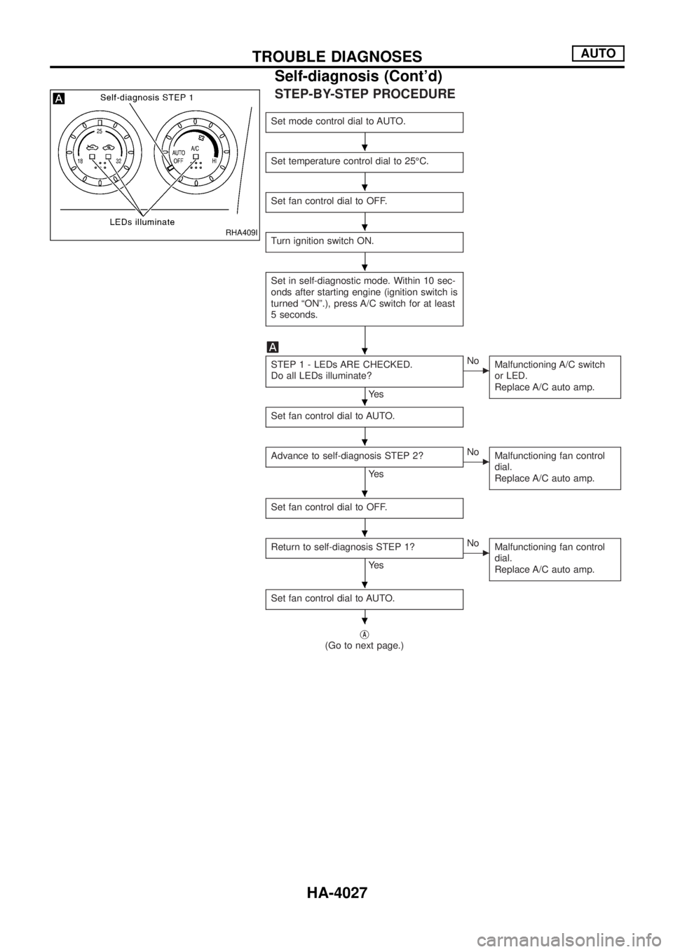
STEP-BY-STEP PROCEDURE
Set mode control dial to AUTO.
Set temperature control dial to 25ÉC.
Set fan control dial to OFF.
Turn ignition switch ON.
Set in self-diagnostic mode. Within 10 sec-
onds after starting engine (ignition switch is
turned ªONº.), press A/C switch for at least
5 seconds.
STEP 1 - LEDs ARE CHECKED.
Do all LEDs illuminate?
Ye s
cNo
Malfunctioning A/C switch
or LED.
Replace A/C auto amp.
Set fan control dial to AUTO.
Advance to self-diagnosis STEP 2?
Ye s
cNo
Malfunctioning fan control
dial.
Replace A/C auto amp.
Set fan control dial to OFF.
Return to self-diagnosis STEP 1?
Ye s
cNo
Malfunctioning fan control
dial.
Replace A/C auto amp.
Set fan control dial to AUTO.
jA
(Go to next page.)
RHA409I
.
.
.
.
.
.
.
.
.
.
.
TROUBLE DIAGNOSESAUTO
Self-diagnosis (Cont'd)
HA-4027
Page 507 of 579
jA
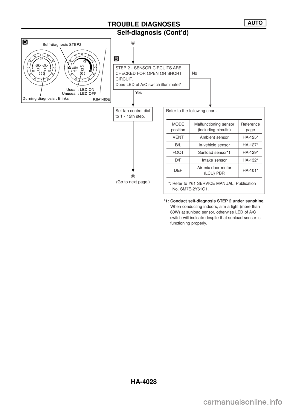
STEP 2 - SENSOR CIRCUITS ARE
CHECKED FOR OPEN OR SHORT
CIRCUIT.
Does LED of A/C switch illuminate?
Ye sNo
.
Set fan control dial
to 1 - 12th step.Refer to the following chart.
*: Refer to Y61 SERVICE MANUAL, Publication
No. SM7E-2Y61G1.
*1: Conduct self-diagnosis STEP 2 under sunshine.
When conducting indoors, aim a light (more than
60W) at sunload sensor, otherwise LED of A/C
switch will indicate despite that sunload sensor is
functioning properly. j
B
(Go to next page.)
MODE
positionMalfunctioning sensor
(including circuits)Reference
page
VENT Ambient sensor HA-125*
B/L In-vehicle sensor HA-127*
FOOT Sunload sensor*1 HA-129*
D/F Intake sensor HA-132*
DEFAir mix door motor
(LCU) PBRHA-101*
RJIA1480E
.
.
.
TROUBLE DIAGNOSESAUTO
Self-diagnosis (Cont'd)
HA-4028
Page 508 of 579
jB
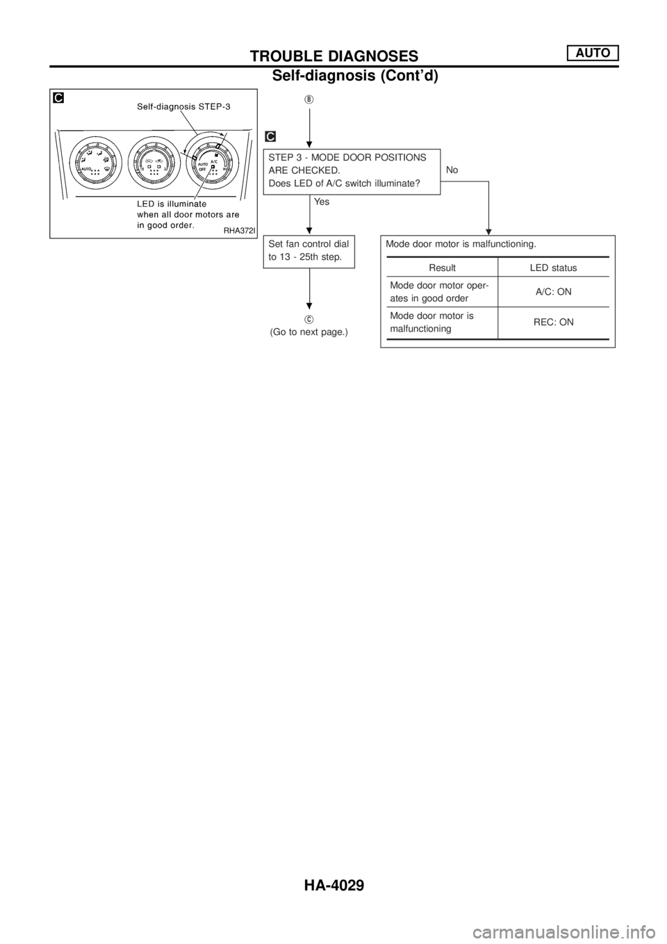
STEP 3 - MODE DOOR POSITIONS
ARE CHECKED.
Does LED of A/C switch illuminate?
Ye sNo
.
Set fan control dial
to 13 - 25th step.Mode door motor is malfunctioning.
jC
(Go to next page.)
Result LED status
Mode door motor oper-
ates in good orderA/C: ON
Mode door motor is
malfunctioningREC: ON
RHA372I
.
.
.
TROUBLE DIAGNOSESAUTO
Self-diagnosis (Cont'd)
HA-4029
Page 509 of 579
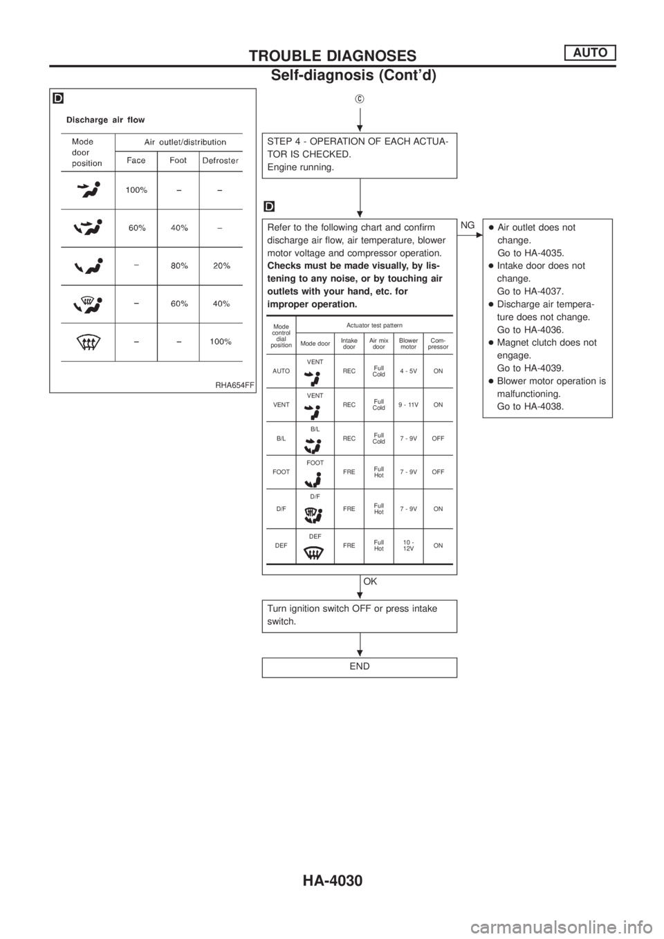
jC
STEP 4 - OPERATION OF EACH ACTUA-
TOR IS CHECKED.
Engine running.
Refer to the following chart and con®rm
discharge air ¯ow, air temperature, blower
motor voltage and compressor operation.
Checks must be made visually, by lis-
tening to any noise, or by touching air
outlets with your hand, etc. for
improper operation.
OK
cNG
+Air outlet does not
change.
Go to HA-4035.
+Intake door does not
change.
Go to HA-4037.
+Discharge air tempera-
ture does not change.
Go to HA-4036.
+Magnet clutch does not
engage.
Go to HA-4039.
+Blower motor operation is
malfunctioning.
Go to HA-4038.
Turn ignition switch OFF or press intake
switch.
END
Mode
control
dial
positionActuator test pattern
Mode doorIntake
doorAir mix
doorBlower
motorCom-
pressor
AUTOVENT
RECFull
Cold4-5V ON
VENTVENT
RECFull
Cold9 - 11V ON
B/LB/L
RECFull
Cold7-9V OFF
FOOTFOOT
FREFull
Hot7-9V OFF
D/FD/F
FREFull
Hot7-9V ON
DEFDEF
FREFull
Hot10 -
12VON
RHA654FF
.
.
.
.
TROUBLE DIAGNOSESAUTO
Self-diagnosis (Cont'd)
HA-4030
Page 510 of 579
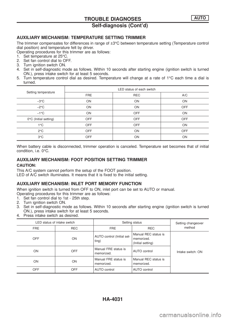
AUXILIARY MECHANISM: TEMPERATURE SETTING TRIMMER
The trimmer compensates for differences in range of 3ÉC between temperature setting (Temperature control
dial position) and temperature felt by driver.
Operating procedures for this trimmer are as follows:
1. Set temperature at 25ÉC.
2. Set fan control dial to OFF.
3. Turn ignition switch ON.
4. Set in self-diagnostic mode as follows. Within 10 seconds after starting engine (ignition switch is turned
ON.), press intake switch for at least 5 seconds.
5. Turn temperature control dial as desired. Temperature will change at a rate of 1ÉC each time a dial is
turned.
Setting temperatureLED status of each switch
FRE REC A/C
þ3ÉC ON ON ON
þ2ÉC ON ON OFF
þ1ÉC ON OFF ON
0ÉC (Initial setting) OFF OFF OFF
1ÉC OFF OFF ON
2ÉC OFF ON OFF
3ÉC OFF ON ON
When battery cable is disconnected, trimmer operation is canceled. Temperature set becomes that of initial
condition, i.e. 0ÉC.
AUXILIARY MECHANISM: FOOT POSITION SETTING TRIMMER
CAUTION:
This A/C system cannot perform the setup of the FOOT position.
LED of A/C switch illuminates. It means that it is ®xed to the initial setting.
AUXILIARY MECHANISM: INLET PORT MEMORY FUNCTION
When ignition switch is turned from OFF to ON, inlet port can be set to AUTO or manual.
Operating procedures for this trimmer are as follows:
1. Set fan control dial to 1st - 25th step.
2. Turn ignition switch ON.
3. Set in self-diagnostic mode as follows. Within 10 seconds after starting engine (ignition switch is turned
ON.), press intake switch for at least 5 seconds.
4. Press intake switch as desired.
LED status of intake switch Setting status
Setting changeover
method
FRE REC FRE REC
OFF ONAUTO control (Initial set-
ting)Manual REC status is
memorized.
(Initial setting)
Intake switch: ON ON OFFManual FRE status is
memorized.AUTO control
ON ONManual FRE status is
memorized.Manual REC status is
memorized.
OFF OFF AUTO control AUTO control
TROUBLE DIAGNOSESAUTO
Self-diagnosis (Cont'd)
HA-4031
Trending: heater, horn, foldout, Gauge, Ecm, turbo, egr


