maintenance NISSAN PICK-UP 1998 Owner's Manual
[x] Cancel search | Manufacturer: NISSAN, Model Year: 1998, Model line: PICK-UP, Model: NISSAN PICK-UP 1998Pages: 1659, PDF Size: 53.39 MB
Page 896 of 1659
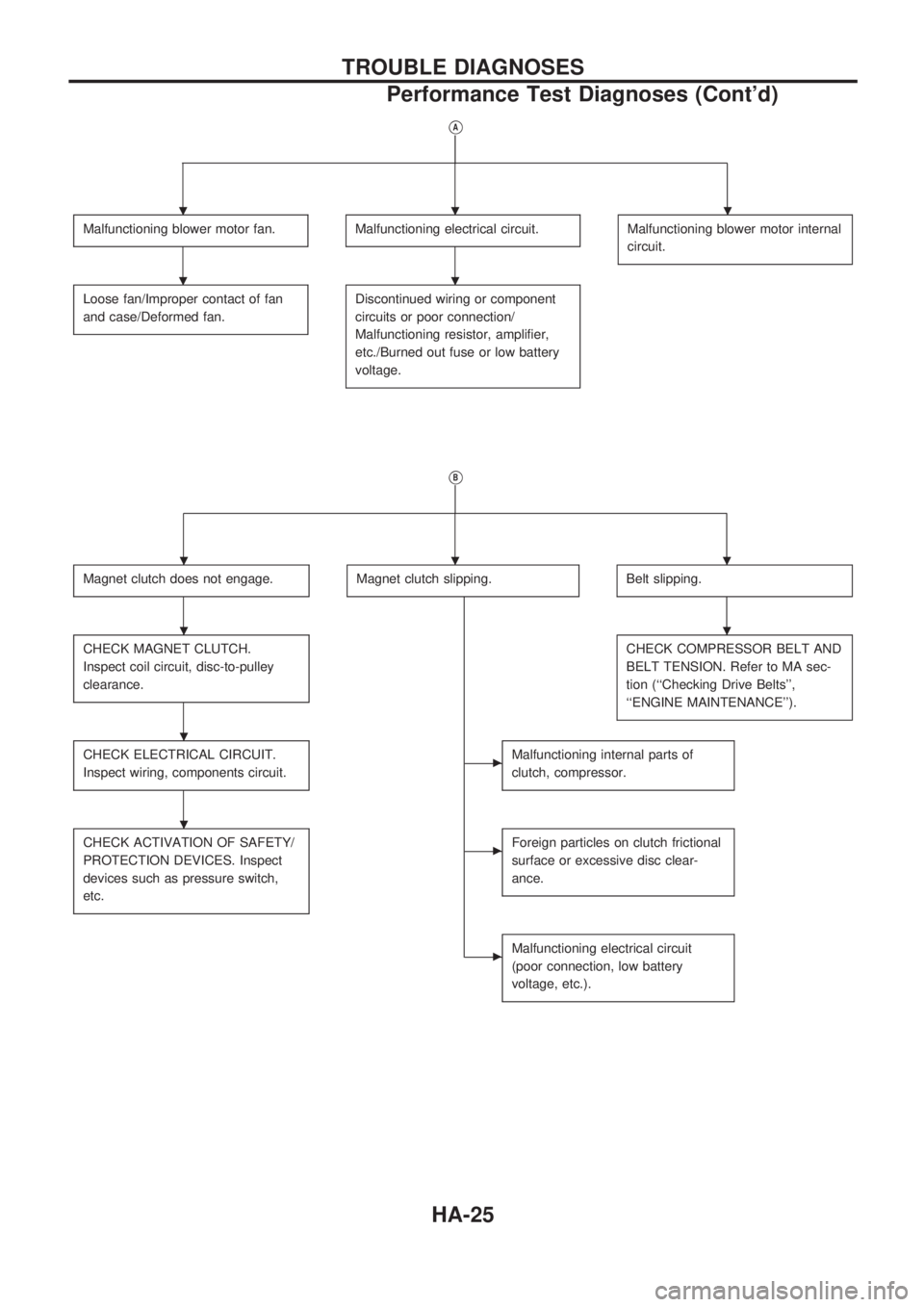
VA
Malfunctioning blower motor fan.Malfunctioning electrical circuit.Malfunctioning blower motor internal
circuit.
Loose fan/Improper contact of fan
and case/Deformed fan.Discontinued wiring or component
circuits or poor connection/
Malfunctioning resistor, amplifier,
etc./Burned out fuse or low battery
voltage.
VB
Magnet clutch does not engage.Magnet clutch slipping.Belt slipping.
CHECK MAGNET CLUTCH.
Inspect coil circuit, disc-to-pulley
clearance.CHECK COMPRESSOR BELT AND
BELT TENSION. Refer to MA sec-
tion (``Checking Drive Belts'',
``ENGINE MAINTENANCE'').
CHECK ELECTRICAL CIRCUIT.
Inspect wiring, components circuit.cMalfunctioning internal parts of
clutch, compressor.
CHECK ACTIVATION OF SAFETY/
PROTECTION DEVICES. Inspect
devices such as pressure switch,
etc.cForeign particles on clutch frictional
surface or excessive disc clear-
ance.
cMalfunctioning electrical circuit
(poor connection, low battery
voltage, etc.).
...
..
...
..
.
.
TROUBLE DIAGNOSES
Performance Test Diagnoses (Cont'd)
HA-25
Page 921 of 1659
Maintenance of Lubricant Quantity in
Compressor
The lubricant used to lubricate the compressor circulates through
the system with the refrigerant. Add lubricant to compressor
when replacing any component or after a large gas leakage
occurred. It is important to maintain the specified amount.
If lubricant quantity is not maintained properly, the following mal-
functions may result:
lLack of lubricant: May lead to a seized compressor
lExcessive lubricant: Inadequate cooling (thermal exchange
interference)
LUBRICANT
Name: Nissan A/C System Oil Type R
Part number: KLH00-PAGR0
CHECKING AND ADJUSTING
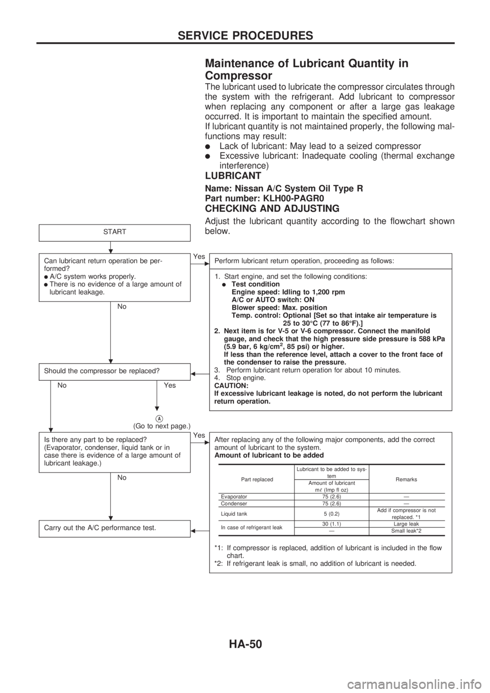
Adjust the lubricant quantity according to the flowchart shown
below.
START
Can lubricant return operation be per-
formed?
lA/C system works properly.lThere is no evidence of a large amount of
lubricant leakage.
No
cYes
Perform lubricant return operation, proceeding as follows:
-----------------------------------------------------------------------------------------------------------------------------------------------------------------------------------------------------------------------------------------------------------------------------------------------------------------------------------------------------------------------------------------------------------------------------------------------------------------------------------------------------------------------------------
1. Start engine, and set the following conditions:
lTest condition
Engine speed: Idling to 1,200 rpm
A/C or AUTO switch: ON
Blower speed: Max. position
Temp. control: Optional [Set so that intake air temperature is
25 to 30ÉC (77 to 86ÉF).]
2. Next item is for V-5 or V-6 compressor. Connect the manifold
gauge, and check that the high pressure side pressure is 588 kPa
(5.9 bar, 6 kg/cm
2, 85 psi) or higher.
If less than the reference level, attach a cover to the front face of
the condenser to raise the pressure.
3. Perform lubricant return operation for about 10 minutes.
4. Stop engine.
CAUTION:
If excessive lubricant leakage is noted, do not perform the lubricant
return operation.
Should the compressor be replaced?
No Yes
b
VA(Go to next page.)
Is there any part to be replaced?
(Evaporator, condenser, liquid tank or in
case there is evidence of a large amount of
lubricant leakage.)
No
cYes
After replacing any of the following major components, add the correct
amount of lubricant to the system.
Amount of lubricant to be added
*1: If compressor is replaced, addition of lubricant is included in the flow
chart.
*2: If refrigerant leak is small, no addition of lubricant is needed.
Carry out the A/C performance test.b
Part replacedLubricant to be added to sys-
tem
Remarks
Amount of lubricant
m!(Imp fl oz)
Evaporator 75 (2.6) Ð
Condenser 75 (2.6) Ð
Liquid tank 5 (0.2)Add if compressor is not
replaced. *1
In case of refrigerant leak30 (1.1) Large leak
Ð Small leak*2
.
.
.
.
.
SERVICE PROCEDURES
HA-50
Page 922 of 1659

VA
1. Discharge refrigerant into the refrigerant recovery/recycling equipment. Measure lubricant discharged into the recovery/
recycling equipment.
2. Remove the drain plug of the ``old'' (removed) compressor (applicable only to V-5, V-6, DKS-16H or DKS-17CH compressor).
Drain the lubricant into a graduated container and record the amount of drained lubricant.
3. Remove the drain plug and drain the lubricant from the ``new'' compressor into a separate, clean container.
4. Measure an amount of new lubricant installed equal to amount drained from ``old'' compressor. Add this lubricant to ``new''
compressor through the suction port opening.
5. Measure an amount of new lubricant equal to the amount recovered during discharging. Add this lubricant to ``new'' compres-
sor through the suction port opening.
6. Torque the drain plug.
V-5 or V-6 compressor: 18 - 19 Nzm (1.8 - 1.9 kg-m, 13 - 14 ft-lb)
DKS-16H compressor: 14 - 16 Nzm (1.4 - 1.6 kg-m, 10 - 12 ft-lb)
DKS-17CH compressor: 14 - 16 Nzm (1.4 - 1.6 kg-m, 10 - 12 ft-lb)
7. If the liquid tank also needs to be replaced, add an additional 5 m!(0.2 Imp fl oz) of lubricant at this time.
Do not add this 5 m!(0.2 Imp fl oz) of lubricant if only replacing the compressor.
RHA065DE
.
SERVICE PROCEDURES
Maintenance of Lubricant Quantity in
Compressor (Cont'd)
HA-51
Page 927 of 1659

Checking Refrigerant Leaks
PRELIMINARY CHECK
Perform a visual inspection of all refrigeration parts, fittings,
hoses, and components for signs of A/C lubricant leakage, dam-
age and corrosion.
PRECAUTIONS FOR HANDLING LEAK DETECTOR
When performing a refrigerant leak check, use an A/C leak
detector or equivalent. Ensure that the instrument is calibrated
and set properly per the operating instructions.
The leak detector is a delicate device. In order to use the leak
detector properly, read the operating instructions and perform
any specified maintenance.
Other gases in the work area or substances on the A/C
components, for example, anti-freeze, windshield washer
fluid, solvents and cleaners, may falsely trigger the leak
detector. Make sure the surfaces to be checked are clean.
Do not allow the sensor tip of the detector to come into
contact with any substance. This can also cause false read-
ings and may damage the detector.
1. Position probe approximately 5 mm (3/16 in) away from point
to be checked.
2. When testing, circle each fitting completely with probe.
SHA705EB
SHA707EA
SHA706E
SERVICE PROCEDURES
HA-56
Page 938 of 1659
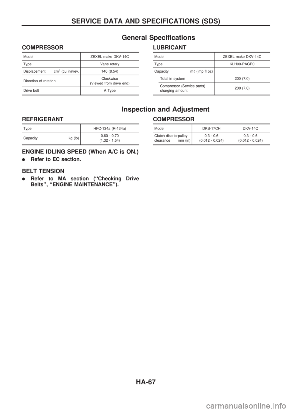
General Specifications
COMPRESSOR
Model ZEXEL make DKV-14C
Type Vane rotary
Displacement cm
3(cu in)/rev. 140 (8.54)
Direction of rotationClockwise
(Viewed from drive end)
Drive belt A Type
LUBRICANT
Model ZEXEL make DKV-14C
Type KLH00-PAGR0
Capacity m!(lmp fl oz)
Total in system 200 (7.0)
Compressor (Service parts)
charging amount200 (7.0)
Inspection and Adjustment
REFRIGERANT
Type HFC-134a (R-134a)
Capacity kg (lb)0.60 - 0.70
(1.32 - 1.54)
ENGINE IDLING SPEED (When A/C is ON.)
lRefer to EC section.
BELT TENSION
lRefer to MA section (``Checking Drive
Belts'', ``ENGINE MAINTENANCE'').
COMPRESSOR
Model DKS-17CH DKV-14C
Clutch disc-to-pulley
clearance mm (in)0.3 - 0.6
(0.012 - 0.024)0.3 - 0.6
(0.012 - 0.024)
SERVICE DATA AND SPECIFICATIONS (SDS)
HA-67
Page 946 of 1659
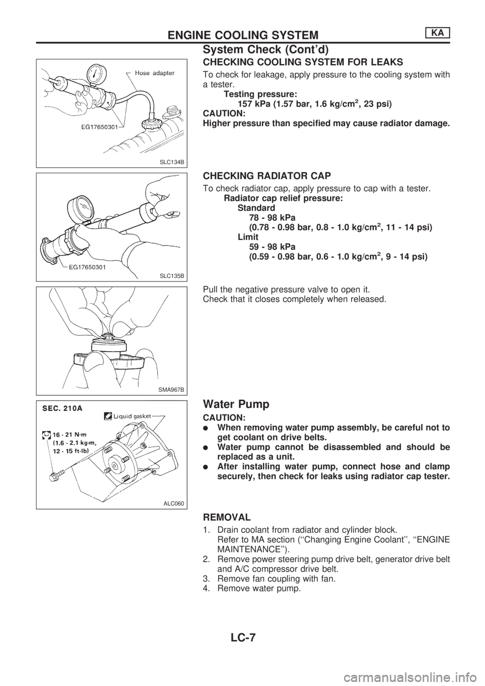
CHECKING COOLING SYSTEM FOR LEAKS
To check for leakage, apply pressure to the cooling system with
a tester.
Testing pressure:
157 kPa (1.57 bar, 1.6 kg/cm
2, 23 psi)
CAUTION:
Higher pressure than specified may cause radiator damage.
CHECKING RADIATOR CAP
To check radiator cap, apply pressure to cap with a tester.
Radiator cap relief pressure:
Standard
78-98kPa
(0.78 - 0.98 bar, 0.8 - 1.0 kg/cm
2, 11 - 14 psi)
Limit
59-98kPa
(0.59 - 0.98 bar, 0.6 - 1.0 kg/cm
2,9-14psi)
Pull the negative pressure valve to open it.
Check that it closes completely when released.
Water Pump
CAUTION:
lWhen removing water pump assembly, be careful not to
get coolant on drive belts.
lWater pump cannot be disassembled and should be
replaced as a unit.
lAfter installing water pump, connect hose and clamp
securely, then check for leaks using radiator cap tester.
REMOVAL
1. Drain coolant from radiator and cylinder block.
Refer to MA section (``Changing Engine Coolant'', ``ENGINE
MAINTENANCE'').
2. Remove power steering pump drive belt, generator drive belt
and A/C compressor drive belt.
3. Remove fan coupling with fan.
4. Remove water pump.
SLC134B
SLC135B
SMA967B
ALC060
ENGINE COOLING SYSTEMKA
System Check (Cont'd)
LC-7
Page 947 of 1659
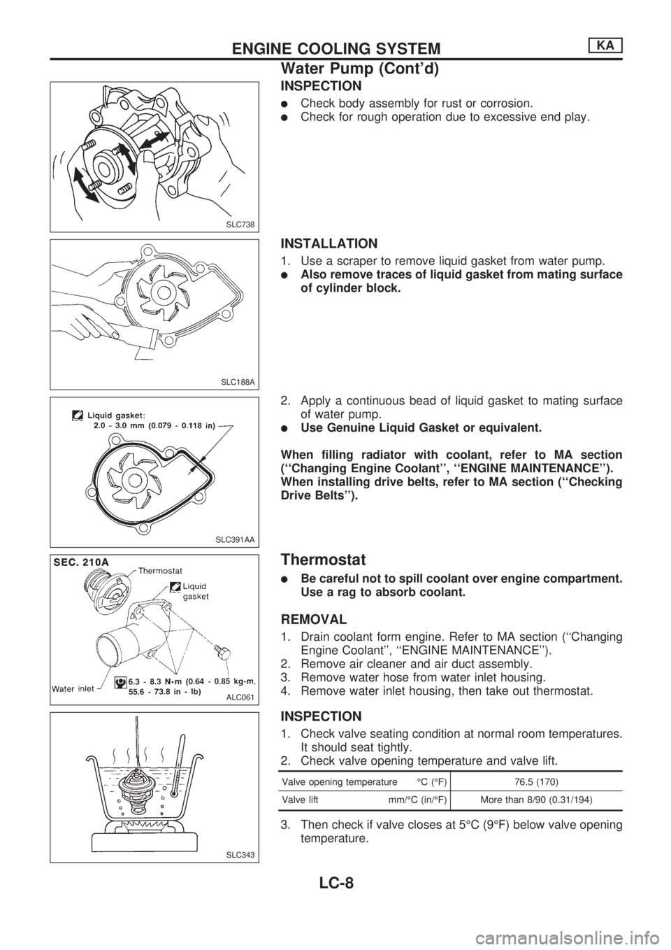
INSPECTION
lCheck body assembly for rust or corrosion.
lCheck for rough operation due to excessive end play.
INSTALLATION
1. Use a scraper to remove liquid gasket from water pump.
lAlso remove traces of liquid gasket from mating surface
of cylinder block.
2. Apply a continuous bead of liquid gasket to mating surface
of water pump.
lUse Genuine Liquid Gasket or equivalent.
When filling radiator with coolant, refer to MA section
(``Changing Engine Coolant'', ``ENGINE MAINTENANCE'').
When installing drive belts, refer to MA section (``Checking
Drive Belts'').
Thermostat
lBe careful not to spill coolant over engine compartment.
Use a rag to absorb coolant.
REMOVAL
1. Drain coolant form engine. Refer to MA section (``Changing
Engine Coolant'', ``ENGINE MAINTENANCE'').
2. Remove air cleaner and air duct assembly.
3. Remove water hose from water inlet housing.
4. Remove water inlet housing, then take out thermostat.
INSPECTION
1. Check valve seating condition at normal room temperatures.
It should seat tightly.
2. Check valve opening temperature and valve lift.
Valve opening temperature ÉC (ÉF) 76.5 (170)
Valve lift mm/ÉC (in/ÉF) More than 8/90 (0.31/194)
3. Then check if valve closes at 5ÉC (9ÉF) below valve opening
temperature.
SLC738
SLC188A
SLC391AA
ALC061
SLC343
ENGINE COOLING SYSTEMKA
Water Pump (Cont'd)
LC-8
Page 948 of 1659
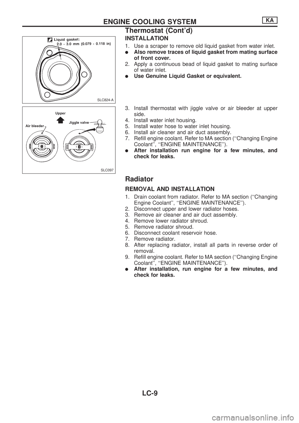
INSTALLATION
1. Use a scraper to remove old liquid gasket from water inlet.
lAlso remove traces of liquid gasket from mating surface
of front cover.
2. Apply a continuous bead of liquid gasket to mating surface
of water inlet.
lUse Genuine Liquid Gasket or equivalent.
3. Install thermostat with jiggle valve or air bleeder at upper
side.
4. Install water inlet housing.
5. Install water hose to water inlet housing.
6. Install air cleaner and air duct assembly.
7. Refill engine coolant. Refer to MA section (``Changing Engine
Coolant'', ``ENGINE MAINTENANCE'').
lAfter installation run engine for a few minutes, and
check for leaks.
Radiator
REMOVAL AND INSTALLATION
1. Drain coolant from radiator. Refer to MA section (``Changing
Engine Coolant'', ``ENGINE MAINTENANCE'').
2. Disconnect upper and lower radiator hoses.
3. Remove air cleaner and air duct assembly.
4. Remove lower radiator shroud.
5. Remove radiator shroud.
6. Disconnect coolant reservoir hose.
7. Remove radiator.
8. After replacing radiator, install all parts in reverse order of
removal.
9. Refill engine coolant. Refer to MA section (``Changing Engine
Coolant'', ``ENGINE MAINTENANCE'').
lAfter installation, run engine for a few minutes, and
check for leaks.
SLC824-A
SLC097
ENGINE COOLING SYSTEMKA
Thermostat (Cont'd)
LC-9
Page 950 of 1659
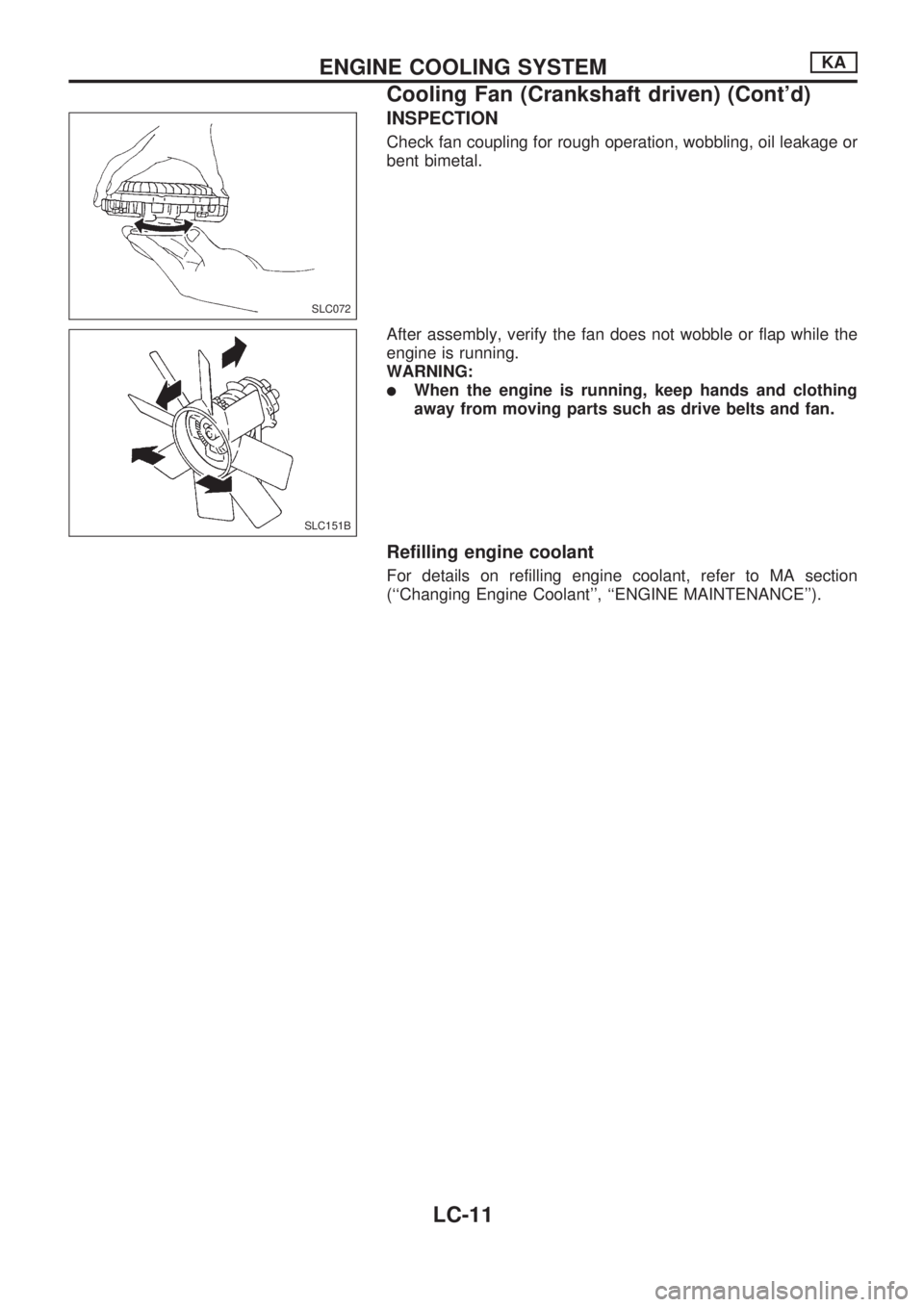
INSPECTION
Check fan coupling for rough operation, wobbling, oil leakage or
bent bimetal.
After assembly, verify the fan does not wobble or flap while the
engine is running.
WARNING:
lWhen the engine is running, keep hands and clothing
away from moving parts such as drive belts and fan.
Refilling engine coolant
For details on refilling engine coolant, refer to MA section
(``Changing Engine Coolant'', ``ENGINE MAINTENANCE'').
SLC072
SLC151B
ENGINE COOLING SYSTEMKA
Cooling Fan (Crankshaft driven) (Cont'd)
LC-11
Page 972 of 1659
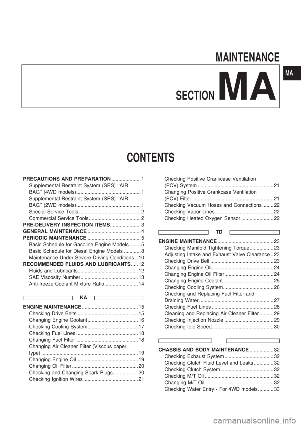
MAINTENANCE
SECTION
MA
CONTENTS
PRECAUTIONS AND PREPARATION..................... 1
Supplemental Restraint System (SRS) ``AIR
BAG'' (4WD models).............................................. 1
Supplemental Restraint System (SRS) ``AIR
BAG'' (2WD models).............................................. 1
Special Service Tools ............................................ 2
Commercial Service Tools ..................................... 2
PRE-DELIVERY INSPECTION ITEMS...................... 3
GENERAL MAINTENANCE...................................... 4
PERIODIC MAINTENANCE...................................... 5
Basic Schedule for Gasoline Engine Models ........ 5
Basic Schedule for Diesel Engine Models ............ 8
Maintenance Under Severe Driving Conditions .. 10
RECOMMENDED FLUIDS AND LUBRICANTS..... 12
Fluids and Lubricants........................................... 12
SAE Viscosity Number......................................... 13
Anti-freeze Coolant Mixture Ratio........................ 14
KA
ENGINE MAINTENANCE........................................ 15
Checking Drive Belts ........................................... 15
Changing Engine Coolant .................................... 16
Checking Cooling System.................................... 17
Checking Fuel Lines ............................................ 18
Changing Fuel Filter ............................................ 18
Changing Air Cleaner Filter (Viscous paper
type) ..................................................................... 19
Changing Engine Oil ............................................ 19
Changing Oil Filter ............................................... 20
Checking and Changing Spark Plugs.................. 20
Checking Ignition Wires ....................................... 21Checking Positive Crankcase Ventilation
(PCV) System ...................................................... 21
Changing Positive Crankcase Ventilation
(PCV) Filter .......................................................... 21
Checking Vacuum Hoses and Connections ........ 22
Checking Vapor Lines.......................................... 22
Checking Heated Oxygen Sensor ....................... 22
TD
ENGINE MAINTENANCE........................................ 23
Checking Manifold Tightening Torque ................. 23
Adjusting Intake and Exhaust Valve Clearance .. 23
Checking Drive Belt ............................................. 23
Changing Engine Oil ............................................ 24
Changing Engine Oil Filter................................... 24
Changing Engine Coolant .................................... 25
Checking Cooling System.................................... 26
Checking and Replacing Fuel Filter and
Draining Water ..................................................... 27
Checking Fuel Lines ............................................ 28
Cleaning and Replacing Air Cleaner Filter .......... 29
Checking Injection Nozzle ................................... 29
Checking Idle Speed............................................ 30
CHASSIS AND BODY MAINTENANCE................. 32
Checking Exhaust System ................................... 32
Checking Clutch Fluid Level and Leaks .............. 32
Checking Clutch System...................................... 32
Checking M/T Oil ................................................. 32
Changing M/T Oil ................................................. 32
Checking Water Entry - For 4WD models ........... 33
MA