tires NISSAN PICK-UP 1998 Repair Manual
[x] Cancel search | Manufacturer: NISSAN, Model Year: 1998, Model line: PICK-UP, Model: NISSAN PICK-UP 1998Pages: 1659, PDF Size: 53.39 MB
Page 439 of 1659
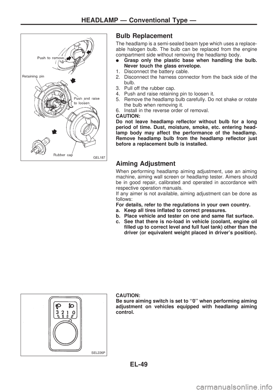
Bulb Replacement
The headlamp is a semi-sealed beam type which uses a replace-
able halogen bulb. The bulb can be replaced from the engine
compartment side without removing the headlamp body.
lGrasp only the plastic base when handling the bulb.
Never touch the glass envelope.
1. Disconnect the battery cable.
2. Disconnect the harness connector from the back side of the
bulb.
3. Pull off the rubber cap.
4. Push and raise retaining pin to loosen it.
5. Remove the headlamp bulb carefully. Do not shake or rotate
the bulb when removing it.
6. Install in the reverse order of removal.
CAUTION:
Do not leave headlamp reflector without bulb for a long
period of time. Dust, moisture, smoke, etc. entering head-
lamp body may affect the performance of the headlamp.
Remove headlamp bulb from the headlamp reflector just
before a replacement bulb is installed.
Aiming Adjustment
When performing headlamp aiming adjustment, use an aiming
machine, aiming wall screen or headlamp tester. Aimers should
be in good repair, calibrated and operated in accordance with
respective operation manuals.
If any aimer is not available, aiming adjustment can be done as
follows:
For details, refer to the regulations in your own country.
a. Keep all tires inflated to correct pressures.
b. Place vehicle and tester on one and same flat surface.
c. See that there is no-load in vehicle (coolant, engine oil
filled up to correct level and full fuel tank) other than the
driver (or equivalent weight placed in driver's position).
CAUTION:
Be sure aiming switch is set to ``0'' when performing aiming
adjustment on vehicles equipped with headlamp aiming
control.
GEL187
SEL226P
HEADLAMP Ð Conventional Type Ð
EL-49
Page 766 of 1659
Precautions
lWhen installing rubber parts, final tightening must be
carried out under unladen condition* with tires on
ground.
* Fuel, radiator coolant and engine oil full. Spare tire,
jack, hand tools and mats in designated positions.
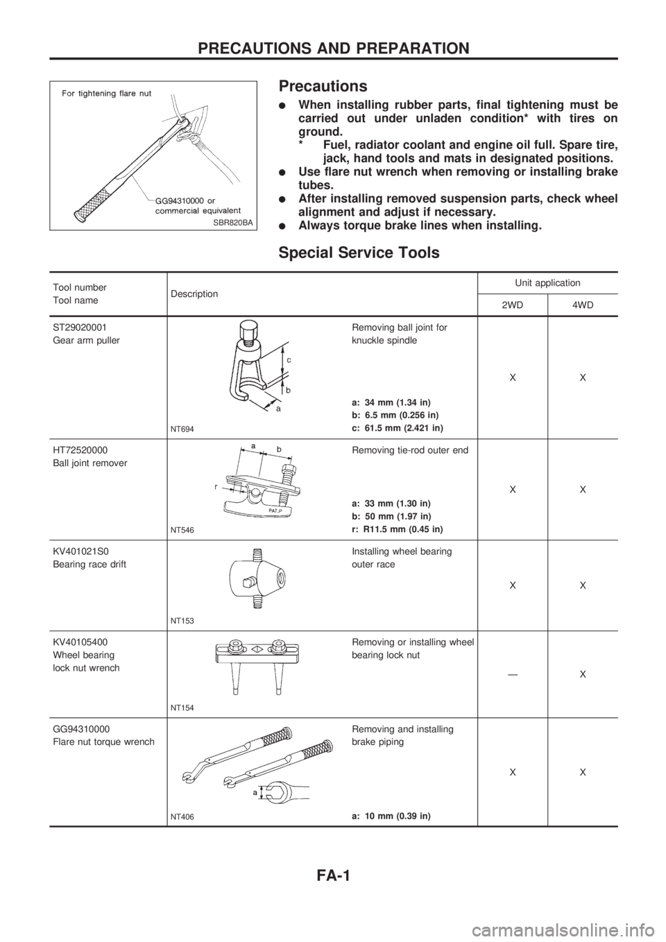
lUse flare nut wrench when removing or installing brake
tubes.
lAfter installing removed suspension parts, check wheel
alignment and adjust if necessary.
lAlways torque brake lines when installing.
Special Service Tools
Tool number
Tool nameDescriptionUnit application
2WD 4WD
ST29020001
Gear arm puller
NT694
Removing ball joint for
knuckle spindle
XX
a: 34 mm (1.34 in)
b: 6.5 mm (0.256 in)
c: 61.5 mm (2.421 in)
HT72520000
Ball joint remover
NT546
Removing tie-rod outer end
XX
a: 33 mm (1.30 in)
b: 50 mm (1.97 in)
r: R11.5 mm (0.45 in)
KV401021S0
Bearing race drift
NT153
Installing wheel bearing
outer race
XX
KV40105400
Wheel bearing
lock nut wrench
NT154
Removing or installing wheel
bearing lock nut
ÐX
GG94310000
Flare nut torque wrench
NT406
Removing and installing
brake piping
XX
a: 10 mm (0.39 in)
SBR820BA
PRECAUTIONS AND PREPARATION
FA-1
Page 772 of 1659
7. Turn wheel hub several times in both directions.
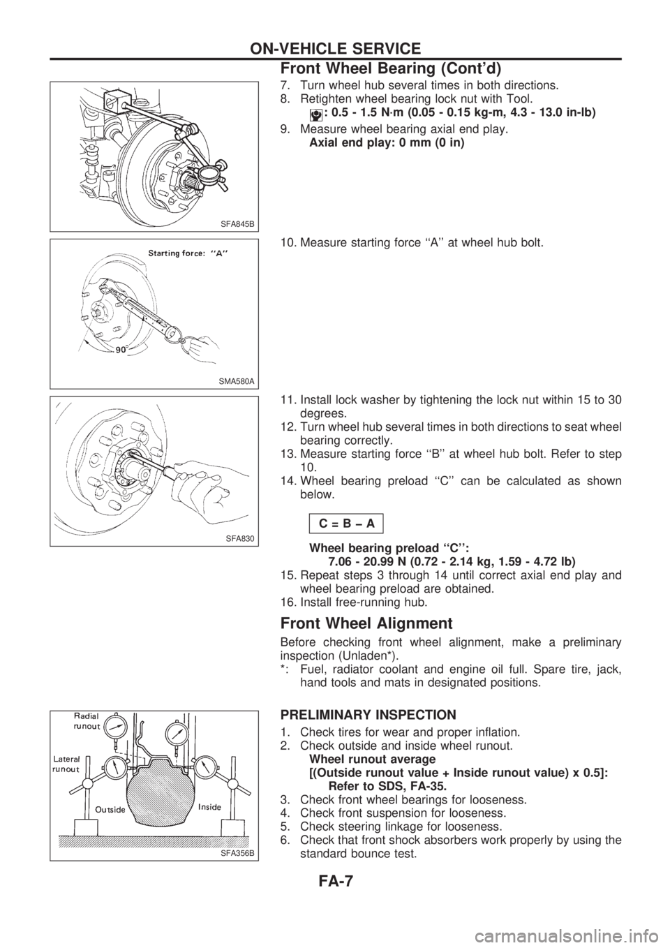
8. Retighten wheel bearing lock nut with Tool.
: 0.5 - 1.5 N´m (0.05 - 0.15 kg-m, 4.3 - 13.0 in-lb)
9. Measure wheel bearing axial end play.
Axial end play: 0 mm (0 in)
10. Measure starting force ``A'' at wheel hub bolt.
11. Install lock washer by tightening the lock nut within 15 to 30
degrees.
12. Turn wheel hub several times in both directions to seat wheel
bearing correctly.
13. Measure starting force ``B'' at wheel hub bolt. Refer to step
10.
14. Wheel bearing preload ``C'' can be calculated as shown
below.
C=BþA
Wheel bearing preload ``C'':
7.06 - 20.99 N (0.72 - 2.14 kg, 1.59 - 4.72 lb)
15. Repeat steps 3 through 14 until correct axial end play and
wheel bearing preload are obtained.
16. Install free-running hub.
Front Wheel Alignment
Before checking front wheel alignment, make a preliminary
inspection (Unladen*).
*: Fuel, radiator coolant and engine oil full. Spare tire, jack,
hand tools and mats in designated positions.
PRELIMINARY INSPECTION
1. Check tires for wear and proper inflation.
2. Check outside and inside wheel runout.
Wheel runout average
[(Outside runout value + Inside runout value) x 0.5]:
Refer to SDS, FA-35.
3. Check front wheel bearings for looseness.
4. Check front suspension for looseness.
5. Check steering linkage for looseness.
6. Check that front shock absorbers work properly by using the
standard bounce test.
SFA845B
SMA580A
SFA830
SFA356B
ON-VEHICLE SERVICE
Front Wheel Bearing (Cont'd)
FA-7
Page 775 of 1659
TOE-IN
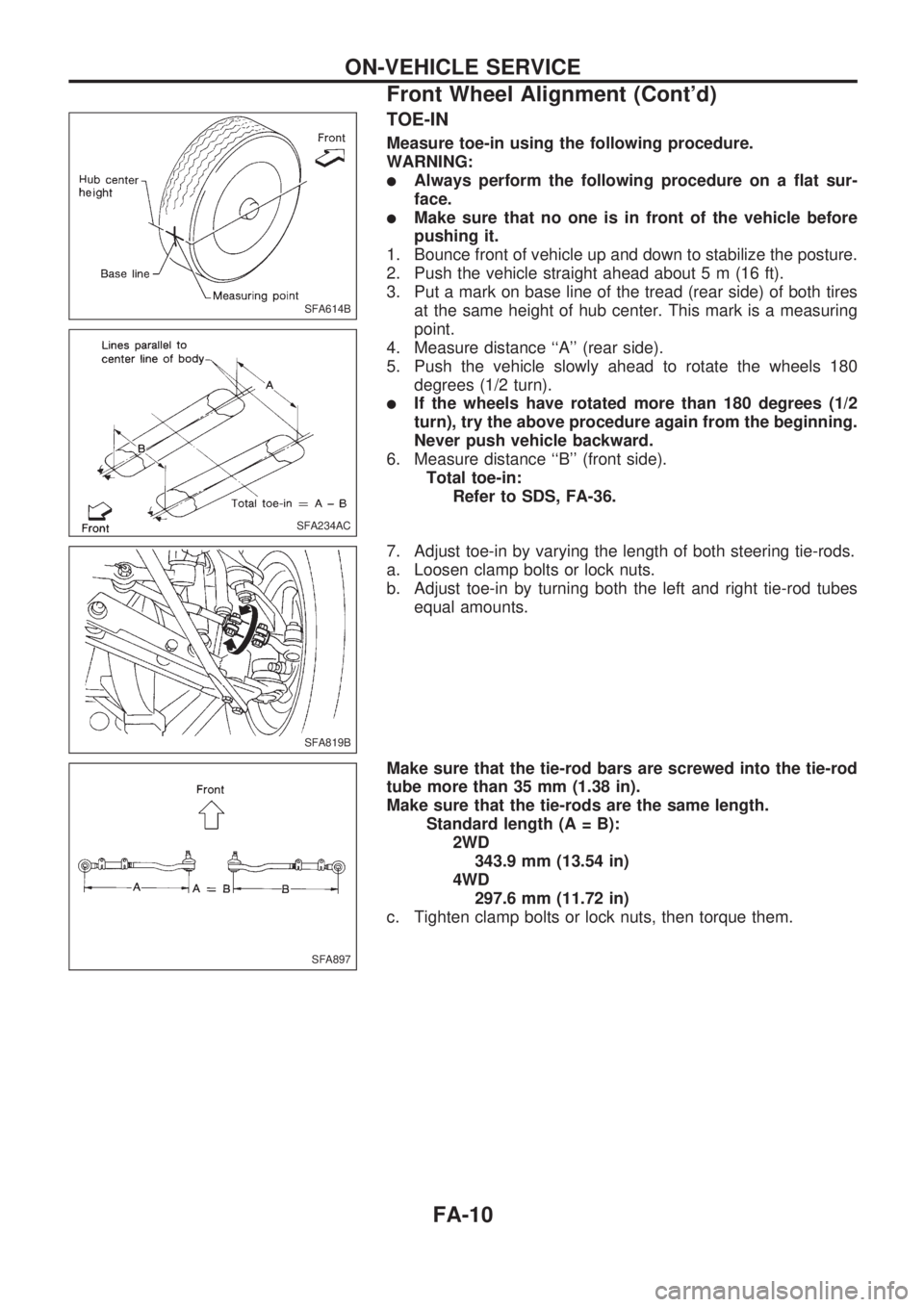
Measure toe-in using the following procedure.
WARNING:
lAlways perform the following procedure on a flat sur-
face.
lMake sure that no one is in front of the vehicle before
pushing it.
1. Bounce front of vehicle up and down to stabilize the posture.
2. Push the vehicle straight ahead about 5 m (16 ft).
3. Put a mark on base line of the tread (rear side) of both tires
at the same height of hub center. This mark is a measuring
point.
4. Measure distance ``A'' (rear side).
5. Push the vehicle slowly ahead to rotate the wheels 180
degrees (1/2 turn).
lIf the wheels have rotated more than 180 degrees (1/2
turn), try the above procedure again from the beginning.
Never push vehicle backward.
6. Measure distance ``B'' (front side).
Total toe-in:
Refer to SDS, FA-36.
7. Adjust toe-in by varying the length of both steering tie-rods.
a. Loosen clamp bolts or lock nuts.
b. Adjust toe-in by turning both the left and right tie-rod tubes
equal amounts.
Make sure that the tie-rod bars are screwed into the tie-rod
tube more than 35 mm (1.38 in).
Make sure that the tie-rods are the same length.
Standard length (A = B):
2WD
343.9 mm (13.54 in)
4WD
297.6 mm (11.72 in)
c. Tighten clamp bolts or lock nuts, then torque them.
SFA614B
SFA234AC
SFA819B
SFA897
ON-VEHICLE SERVICE
Front Wheel Alignment (Cont'd)
FA-10
Page 795 of 1659
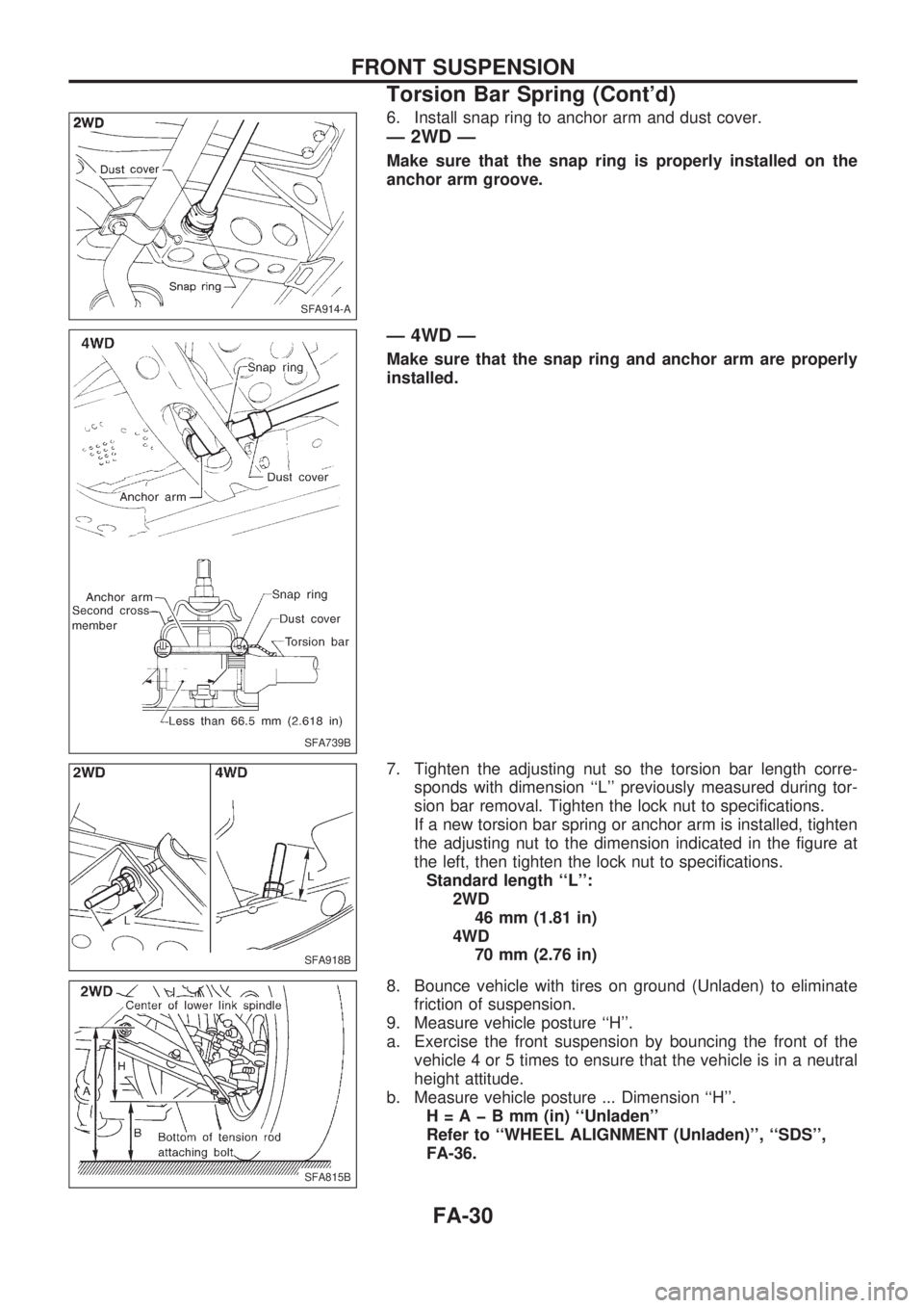
6. Install snap ring to anchor arm and dust cover.
Ð 2WD Ð
Make sure that the snap ring is properly installed on the
anchor arm groove.
Ð 4WD Ð
Make sure that the snap ring and anchor arm are properly
installed.
7. Tighten the adjusting nut so the torsion bar length corre-
sponds with dimension ``L'' previously measured during tor-
sion bar removal. Tighten the lock nut to specifications.
If a new torsion bar spring or anchor arm is installed, tighten
the adjusting nut to the dimension indicated in the figure at
the left, then tighten the lock nut to specifications.
Standard length ``L'':
2WD
46 mm (1.81 in)
4WD
70 mm (2.76 in)
8. Bounce vehicle with tires on ground (Unladen) to eliminate
friction of suspension.
9. Measure vehicle posture ``H''.
a. Exercise the front suspension by bouncing the front of the
vehicle 4 or 5 times to ensure that the vehicle is in a neutral
height attitude.
b. Measure vehicle posture ... Dimension ``H''.
H=AþBmm(in) ``Unladen''
Refer to ``WHEEL ALIGNMENT (Unladen)'', ``SDS'',
FA-36.
SFA914-A
SFA739B
SFA918B
SFA815B
FRONT SUSPENSION
Torsion Bar Spring (Cont'd)
FA-30
Page 797 of 1659
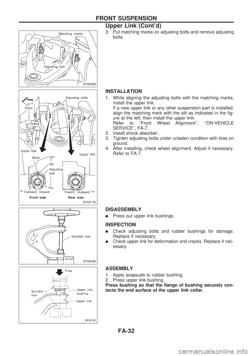
3. Put matching marks on adjusting bolts and remove adjusting
bolts.
INSTALLATION
1. While aligning the adjusting bolts with the matching marks,
install the upper link.
If a new upper link or any other suspension part is installed,
align the matching mark with the slit as indicated in the fig-
ure at the left, then install the upper link.
Refer to ``Front Wheel Alignment'', ``ON-VEHICLE
SERVICE'', FA-7.
2. Install shock absorber.
3. Tighten adjusting bolts under unladen condition with tires on
ground.
4. After installing, check wheel alignment. Adjust if necessary.
Refer to FA-7.
DISASSEMBLY
lPress out upper link bushings.
INSPECTION
lCheck adjusting bolts and rubber bushings for damage.
Replace if necessary.
lCheck upper link for deformation and cracks. Replace if nec-
essary.
ASSEMBLY
1. Apply soapsuds to rubber bushing.
2. Press upper link bushing.
Press bushing so that the flange of bushing securely con-
tacts the end surface of the upper link collar.
SFA842B
SFA817B
SFA843B
SFA102
FRONT SUSPENSION
Upper Link (Cont'd)
FA-32
Page 804 of 1659
GENERAL INFORMATION
SECTION
GI
CONTENTS
PRECAUTIONS......................................................... 1
Precautions for Supplemental Restraint
System (SRS) ``AIR BAG'' (4WD models)............. 1
Precautions for Supplemental Restraint
System (SRS) ``AIR BAG'' (2WD models)............. 1
Precautions for NATS ............................................ 2
General Precautions .............................................. 2
Precautions for Multiport Fuel Injection System
or ECCS Engine .................................................... 4
Precautions for Three Way Catalyst
(If so equipped) ...................................................... 4
Precautions for Engine Oils ................................... 4
Precautions for Fuel............................................... 5
Precautions for Air Conditioning ............................ 6
HOW TO USE THIS MANUAL.................................. 7
HOW TO READ WIRING DIAGRAMS...................... 9
Sample/Wiring Diagram - EXAMPL - .................... 9
Description ........................................................... 11
HOW TO CHECK TERMINAL................................. 18
How to Probe Connectors ................................... 18
How to Check Enlarged Contact Spring of
Terminal ............................................................... 19
Waterproof Connector Inspection ........................ 20
Terminal Lock Inspection ..................................... 20
HOW TO PERFORM EFFICIENT DIAGNOSIS
FOR AN ELECTRICAL INCIDENT......................... 21
Work Flow ............................................................ 21HOW TO PERFORM EFFICIENT DIAGNOSIS...... 22
Incident Simulation Tests..................................... 22
Circuit Inspection ................................................. 25
HOW TO FOLLOW FLOW CHART IN
TROUBLE DIAGNOSES......................................... 31
How to Follow This Flow Chart ........................... 32
CONSULT CHECKING SYSTEM............................ 34
Function and System Application ........................ 34
Lithium Battery Replacement............................... 34
Checking Equipment ............................................ 35
Loading Procedure............................................... 36
CONSULT Data Link Connector (DLC) Circuit ... 36
IDENTIFICATION INFORMATION.......................... 37
Model Variation .................................................... 37
Identification Number ........................................... 40
Dimensions .......................................................... 44
Wheels and Tires ................................................. 46
LIFTING POINTS AND TOW TRUCK TOWING..... 47
Pantograph Jack .................................................. 47
Screw Jack........................................................... 48
Garage Jack and Safety Stand ........................... 49
2-pole Lift ............................................................. 50
Tow Truck Towing ............................................... 51
Towing Point ........................................................ 53
TIGHTENING TORQUE OF STANDARD BOLTS.. 54
SAE J1930 TERMINOLOGY LIST.......................... 55
SAE J1930 Terminology List ............................... 55
GI
Page 849 of 1659
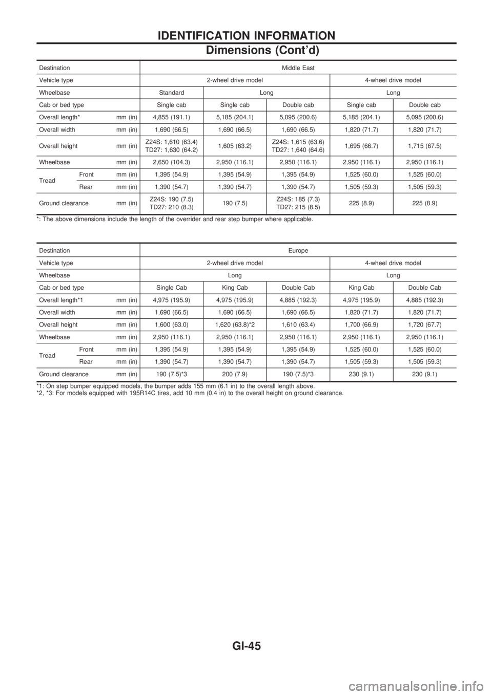
DestinationMiddle East
Vehicle type 2-wheel drive model 4-wheel drive model
Wheelbase Standard Long Long
Cab or bed type Single cab Single cab Double cab Single cab Double cab
Overall length* mm (in) 4,855 (191.1) 5,185 (204.1) 5,095 (200.6) 5,185 (204.1) 5,095 (200.6)
Overall width mm (in) 1,690 (66.5) 1,690 (66.5) 1,690 (66.5) 1,820 (71.7) 1,820 (71.7)
Overall height mm (in)Z24S: 1,610 (63.4)
TD27: 1,630 (64.2)1,605 (63.2)Z24S: 1,615 (63.6)
TD27: 1,640 (64.6)1,695 (66.7) 1,715 (67.5)
Wheelbase mm (in) 2,650 (104.3) 2,950 (116.1) 2,950 (116.1) 2,950 (116.1) 2,950 (116.1)
TreadFront mm (in) 1,395 (54.9) 1,395 (54.9) 1,395 (54.9) 1,525 (60.0) 1,525 (60.0)
Rear mm (in) 1,390 (54.7) 1,390 (54.7) 1,390 (54.7) 1,505 (59.3) 1,505 (59.3)
Ground clearance mm (in)Z24S: 190 (7.5)
TD27: 210 (8.3)190 (7.5)Z24S: 185 (7.3)
TD27: 215 (8.5)225 (8.9) 225 (8.9)
*: The above dimensions include the length of the overrider and rear step bumper where applicable.
DestinationEurope
Vehicle type 2-wheel drive model 4-wheel drive model
Wheelbase Long Long
Cab or bed type Single Cab King Cab Double Cab King Cab Double Cab
Overall length*1 mm (in) 4,975 (195.9) 4,975 (195.9) 4,885 (192.3) 4,975 (195.9) 4,885 (192.3)
Overall width mm (in) 1,690 (66.5) 1,690 (66.5) 1,690 (66.5) 1,820 (71.7) 1,820 (71.7)
Overall height mm (in) 1,600 (63.0) 1,620 (63.8)*2 1,610 (63.4) 1,700 (66.9) 1,720 (67.7)
Wheelbase mm (in) 2,950 (116.1) 2,950 (116.1) 2,950 (116.1) 2,950 (116.1) 2,950 (116.1)
TreadFront mm (in) 1,395 (54.9) 1,395 (54.9) 1,395 (54.9) 1,525 (60.0) 1,525 (60.0)
Rear mm (in) 1,390 (54.7) 1,390 (54.7) 1,390 (54.7) 1,505 (59.3) 1,505 (59.3)
Ground clearance mm (in) 190 (7.5)*3 200 (7.9) 190 (7.5)*3 230 (9.1) 230 (9.1)
*1: On step bumper equipped models, the bumper adds 155 mm (6.1 in) to the overall length above.
*2, *3: For models equipped with 195R14C tires, add 10 mm (0.4 in) to the overall height on ground clearance.
IDENTIFICATION INFORMATION
Dimensions (Cont'd)
GI-45
Page 850 of 1659
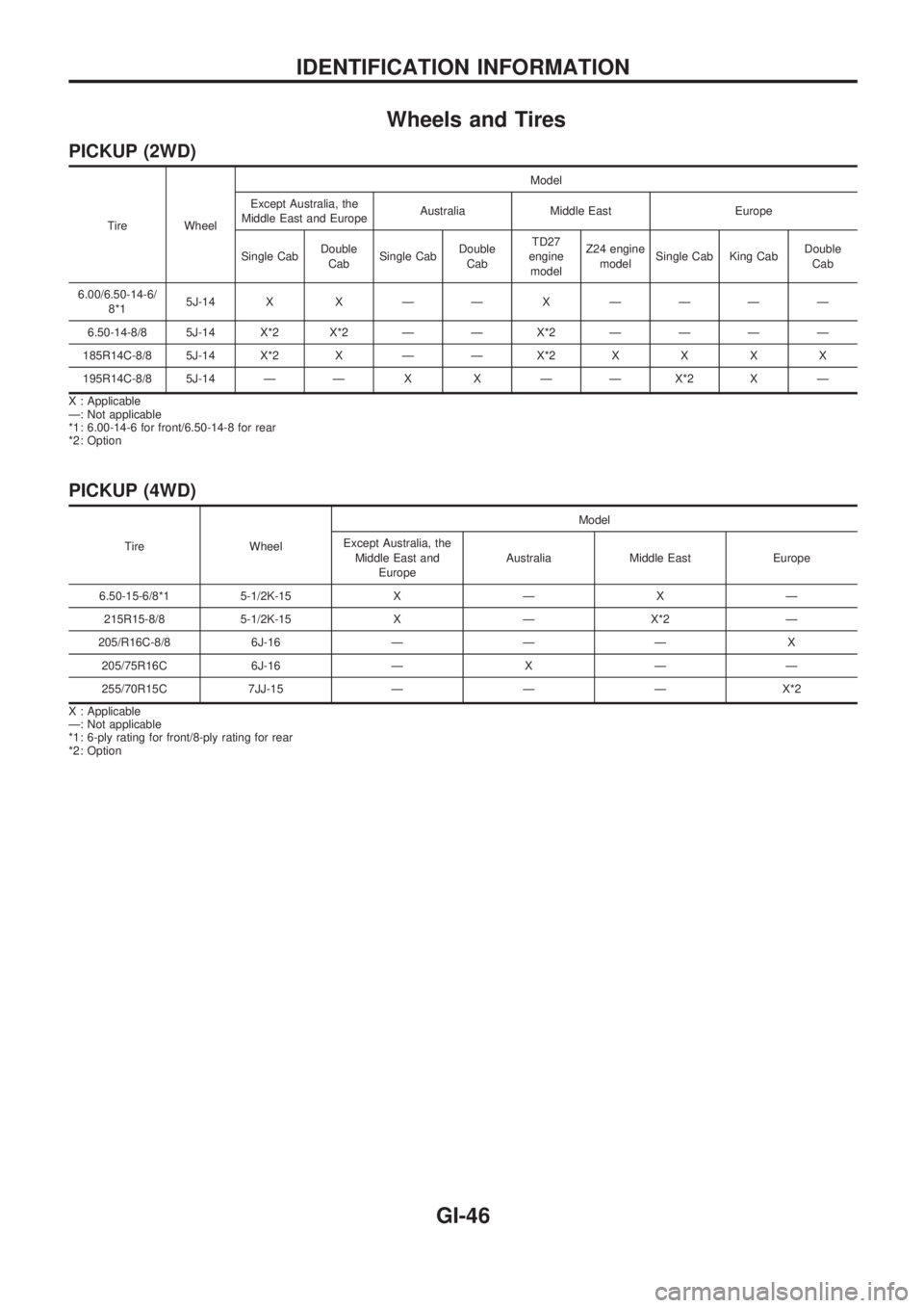
Wheels and Tires
PICKUP (2WD)
Tire WheelModel
Except Australia, the
Middle East and EuropeAustralia Middle East Europe
Single CabDouble
CabSingle CabDouble
CabTD27
engine
modelZ24 engine
modelSingle Cab King CabDouble
Cab
6.00/6.50-14-6/
8*15J-14 X X Ð Ð XÐÐÐÐ
6.50-14-8/8 5J-14 X*2 X*2 Ð Ð X*2ÐÐÐÐ
185R14C-8/8 5J-14 X*2 X Ð Ð X*2XXXX
195R14C-8/8 5J-14 Ð Ð X X Ð Ð X*2 X Ð
X : Applicable
Ð: Not applicable
*1 : 6.00-14-6 for front/6.50-14-8 for rear
*2 : Option
PICKUP (4WD)
Tire WheelModel
Except Australia, the
Middle East and
EuropeAustralia Middle East Europe
6.50-15-6/8*1 5-1/2K-15 X Ð X Ð
215R15-8/8 5-1/2K-15 X Ð X*2 Ð
205/R16C-8/8 6J-16 Ð Ð Ð X
205/75R16C 6J-16 Ð X Ð Ð
255/70R15C 7JJ-15 Ð Ð Ð X*2
X : Applicable
Ð: Not applicable
*1 : 6-ply rating for front/8-ply rating for rear
*2 : Option
IDENTIFICATION INFORMATION
GI-46
Page 970 of 1659
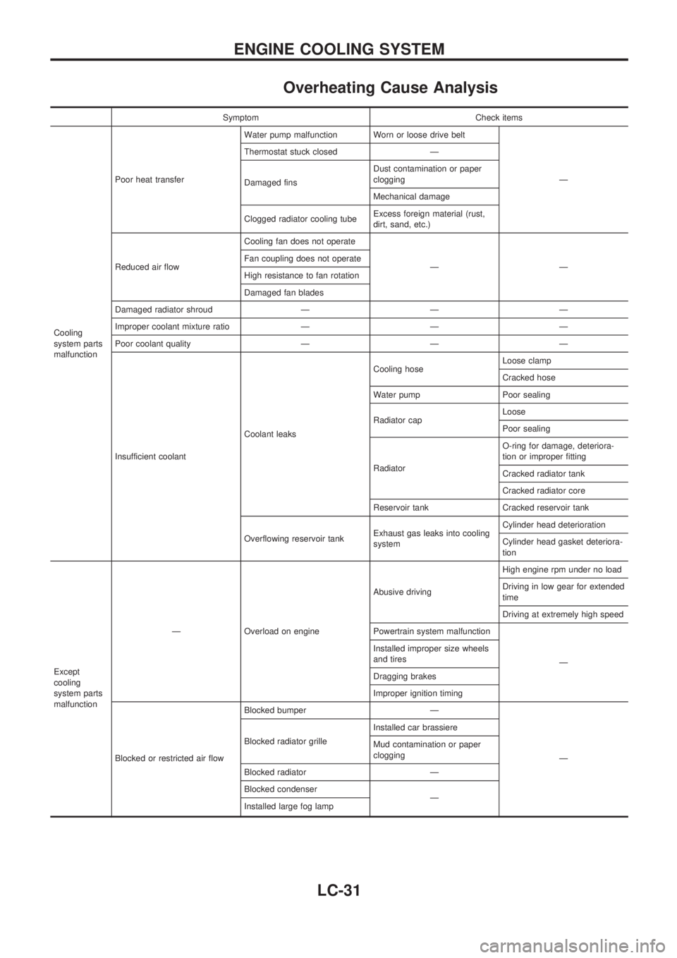
Overheating Cause Analysis
Symptom Check items
Cooling
system parts
malfunctionPoor heat transferWater pump malfunction Worn or loose drive belt
Ð Thermostat stuck closed Ð
Damaged finsDust contamination or paper
clogging
Mechanical damage
Clogged radiator cooling tubeExcess foreign material (rust,
dirt, sand, etc.)
Reduced air flowCooling fan does not operate
ÐÐ Fan coupling does not operate
High resistance to fan rotation
Damaged fan blades
Damaged radiator shroud Ð Ð Ð
Improper coolant mixture ratio Ð Ð Ð
Poor coolant quality Ð Ð Ð
Insufficient coolantCoolant leaksCooling hoseLoose clamp
Cracked hose
Water pump Poor sealing
Radiator capLoose
Poor sealing
RadiatorO-ring for damage, deteriora-
tion or improper fitting
Cracked radiator tank
Cracked radiator core
Reservoir tank Cracked reservoir tank
Overflowing reservoir tankExhaust gas leaks into cooling
systemCylinder head deterioration
Cylinder head gasket deteriora-
tion
Except
cooling
system parts
malfunctionÐ Overload on engineAbusive drivingHigh engine rpm under no load
Driving in low gear for extended
time
Driving at extremely high speed
Powertrain system malfunction
Ð Installed improper size wheels
and tires
Dragging brakes
Improper ignition timing
Blocked or restricted air flowBlocked bumper Ð
Ð Blocked radiator grilleInstalled car brassiere
Mud contamination or paper
clogging
Blocked radiator Ð
Blocked condenser
Ð
Installed large fog lamp
ENGINE COOLING SYSTEM
LC-31