height NISSAN PICK-UP 1998 Workshop Manual
[x] Cancel search | Manufacturer: NISSAN, Model Year: 1998, Model line: PICK-UP, Model: NISSAN PICK-UP 1998Pages: 1659, PDF Size: 53.39 MB
Page 1153 of 1659

Differential Carrier
1. Press-fit front and rear bearing outer races with Tools.
Tool numbers:
VAST30611000
VBST30621000
VCST30613000
2. Select drive pinion height adjusting washer. Refer to
``ADJUSTMENT'', PD-67.
3. Install drive pinion adjusting washer in drive pinion, and
press-fit pinion rear bearing inner cone in it, with press and
Tool.
Tool number: ST30901000
4. Place pinion front bearing inner cone in gear carrier.
5. Apply multi-purpose grease to cavity at sealing lips of oil
seal. Install front oil seal.
Tool numbers:
VAST15310000
VBKV40104710
SPD580
SPD377
SPD581
SPD291A
ASSEMBLYH233B
PD-72
Page 1159 of 1659

INSPECTION AND ADJUSTMENT (R180A)
Ring gear runout
Ring gear runout limit mm (in) 0.05 (0.0020)
Axle bearing adjustment
Axle bearing end play mm (in) 0 - 0.1 (0 - 0.004)
Available axle bearing adjusting shims
Thickness mm (in) Part number
0.10 (0.0039)
0.20 (0.0079)
0.30 (0.0118)
0.40 (0.0157)38233-01G11
38233-01G12
38233-01G13
38233-01G14
Side gear adjustment
Side gear backlash
(Clearance between side gear and
differential case) mm (in)Less than 0.15 (0.0059)
Available side gear thrust washers
Thickness mm (in) Part number
0.75 (0.0295)
0.78 (0.0307)
0.81 (0.0319)
0.84 (0.0331)
0.87 (0.0343)
0.90 (0.0354)
0.93 (0.0366)
0.96 (0.0378)38424-W2010
38424-W2011
38424-W2012
38424-W2013
38424-W2014
38424-W2015
38424-W2016
38424-W2017
Side bearing adjustment
Differential carrier assembly turning
resistance
N (kg, lb)34.3 - 39.2
(3.5 - 4.0, 7.7 - 8.8)
Side bearing adjusting method Adjusting shim
Available side retainer shims
Thickness mm (in) Part number
0.20 (0.0079)
0.25 (0.0098)
0.30 (0.0118)
0.40 (0.0157)
0.50 (0.0197)38453-01G00
38453-01G01
38453-01G02
38453-01G03
38453-01G04
Total preload adjustment
Total preload
N´m (kg-cm, in-lb)1.2 - 2.3
(12 - 23, 10 - 20)
Ring gear backlash mm (in)0.13 - 0.18
(0.0051 - 0.0071)
Drive pinion height adjustment
Available pinion height adjusting washers
Thickness mm (in) Part number
3.09 (0.1217)
3.12 (0.1228)
3.15 (0.1240)
3.18 (0.1252)
3.21 (0.1264)
3.24 (0.1276)
3.27 (0.1287)
3.30 (0.1299)
3.33 (0.1311)
3.36 (0.1323)
3.39 (0.1335)
3.42 (0.1346)
3.45 (0.1358)
3.48 (0.1370)
3.51 (0.1382)
3.54 (0.1394)
3.57 (0.1406)
3.60 (0.1417)
3.63 (0.1429)
3.66 (0.1441)38154-P6017
38154-P6018
38154-P6019
38154-P6020
38154-P6021
38154-P6022
38154-P6023
38154-P6024
38154-P6025
38154-P6026
38154-P6027
38154-P6028
38154-P6029
38154-P6030
38154-P6031
38154-P6032
38154-P6033
38154-P6034
38154-P6035
38154-P6036
Drive pinion preload adjustment
Drive pinion bearing preload
adjusting methodAdjusting washer
and spacer
Drive pinion preload
N´m (kg-cm, in-lb)
With front oil seal1.1 - 1.7
(11 - 17, 9.5 - 14.8)
Without front oil seal1.0 - 1.6
(10 - 16, 8.7 - 13.9)
Available drive pinion bearing preload adjusting washers
Thickness mm (in) Part number
6.58 - 6.60 (0.2591 - 0.2598)
6.56 - 6.58 (0.2583 - 0.2591)
6.54 - 6.56 (0.2575 - 0.2583)
6.52 - 6.54 (0.2567 - 0.2575)
6.50 - 6.52 (0.2559 - 0.2567)
6.48 - 6.50 (0.2551 - 0.2559)
6.46 - 6.48 (0.2543 - 0.2551)
6.44 - 6.46 (0.2535 - 0.2543)
6.42 - 6.44 (0.2528 - 0.2535)
6.40 - 6.42 (0.2520 - 0.2528)
6.38 - 6.40 (0.2512 - 0.2520)
6.36 - 6.38 (0.2504 - 0.2512)
6.34 - 6.36 (0.2496 - 0.2504)
6.32 - 6.34 (0.2488 - 0.2496)
6.30 - 6.32 (0.2480 - 0.2488)38127-01G00
38127-01G01
38127-01G02
38127-01G03
38127-01G04
38127-01G05
38127-01G06
38127-01G07
38127-01G08
38127-01G09
38127-01G10
38127-01G11
38127-01G12
38127-01G13
38127-01G14
Available drive pinion bearing preload adjusting spacers
Length mm (in) Part number
52.20 (2.0551)
52.40 (2.0630)
52.60 (2.0709)
52.80 (2.0787)
53.00 (2.0866)
53.20 (2.0945)38130-78500
38131-78500
38132-78500
38133-78500
38134-78500
38135-78500
SERVICE DATA AND SPECIFICATIONS (SDS)
Final Drive (Cont'd)
PD-78
Page 1160 of 1659

INSPECTION AND ADJUSTMENT (C200)
Ring gear runout
Ring gear runout limit mm (in) 0.05 (0.0020)
Side gear adjustment (without LSD)
Side gear backlash
(Clearance between side gear and
differential case) mm (in)Less than 0.15 (0.0059)
Available side gear thrust washers (2WD)
Thickness mm (in) Part number
0.75 (0.0295)
0.78 (0.0307)
0.81 (0.0319)
0.84 (0.0331)
0.87 (0.0343)
0.90 (0.0354)
0.93 (0.0366)38424-N3110
38424-N3111
38424-N3112
38424-N3113
38424-N3114
38424-N3115
38424-N3116
Available side gear thrust washers (4WD)
Thickness mm (in) Part number
0.75 (0.0295)
0.80 (0.0315)
0.85 (0.0335)
0.90 (0.0354)38424-E3000
38424-E3001
38424-E3002
38424-E3003
Side bearing adjustment
Differential carrier assembly turning
resistance N (kg, lb)34.3 - 39.2
(3.5 - 4.0, 7.7 - 8.8)
Available side bearing adjusting washers
Thickness mm (in) Part number
2.00 (0.0787)
2.05 (0.0807)
2.10 (0.0827)
2.15 (0.0846)
2.20 (0.0866)
2.25 (0.0886)
2.30 (0.0906)
2.35 (0.0925)
2.40 (0.0945)
2.45 (0.0965)
2.50 (0.0984)
2.55 (0.1004)
2.60 (0.1024)38453-N3100
38453-N3101
38453-N3102
38453-N3103
38453-N3104
38453-N3105
38453-N3106
38453-N3107
38453-N3108
38453-N3109
38453-N3110
38453-N3111
38453-N3112
Drive pinion height adjustment
Available pinion height adjusting washers
Thickness mm (in) Part number
3.09 (0.1217)
3.12 (0.1228)
3.15 (0.1240)
3.18 (0.1252)
3.21 (0.1264)
3.24 (0.1276)
3.27 (0.1287)
3.30 (0.1299)
3.33 (0.1311)
3.36 (0.1323)
3.39 (0.1335)
3.42 (0.1346)
3.45 (0.1358)
3.48 (0.1370)
3.51 (0.1382)
3.54 (0.1394)
3.57 (0.1406)
3.60 (0.1417)
3.63 (0.1429)
3.66 (0.1441)38154-P6017
38154-P6018
38154-P6019
38154-P6020
38154-P6021
38154-P6022
38154-P6023
38154-P6024
38154-P6025
38154-P6026
38154-P6027
38154-P6028
38154-P6029
38154-P6030
38154-P6031
38154-P6032
38154-P6033
38154-P6034
38154-P6035
38154-P6036
Drive pinion preload adjustment
Drive pinion bearing preload
adjusting methodCollapsible spacer
Drive pinion preload
N´m (kg-cm, in-lb)
With front oil seal 1.1 - 1.7 (11 - 17, 9.5 - 14.8)
Without front oil seal 1.0 - 1.6 (10 - 16, 8.7 - 13.9)
Total preload adjustment
Total preload
N´m (kg-cm, in-lb)1.2 - 2.3
(12 - 23, 10 - 20)
Ring gear backlash mm (in)0.13 - 0.18
(0.0051 - 0.0071)
Ð Additional service for LSD model Ð
Differential torque adjustment
Differential torque
N´m (kg-m, ft-lb)88 - 108
(9.0 - 11.0, 65 - 80)
Number of discs and plates
Friction disc
Friction plate
Spring plate12
12
2
Wear limit of plate and disc
mm (in)0.1 (0.004)
Allowable warpage of friction disc
and plate mm (in)0.08 (0.0031)
Total thickness mm (in) 19.24 - 20.36 (0.7575 - 0.8016)
Available discs and plates
Part name Thickness mm (in) Part number
Friction disc1.5 (0.059)38433-C6002
(Standard type)
1.6 (0.063)38433-C6003
(Adjusting type)
Friction plate 1.5 (0.059) 38432-C6001
Spring plate 1.5 (0.059) 38435-C6011
SERVICE DATA AND SPECIFICATIONS (SDS)
Final Drive (Cont'd)
PD-79
Page 1161 of 1659
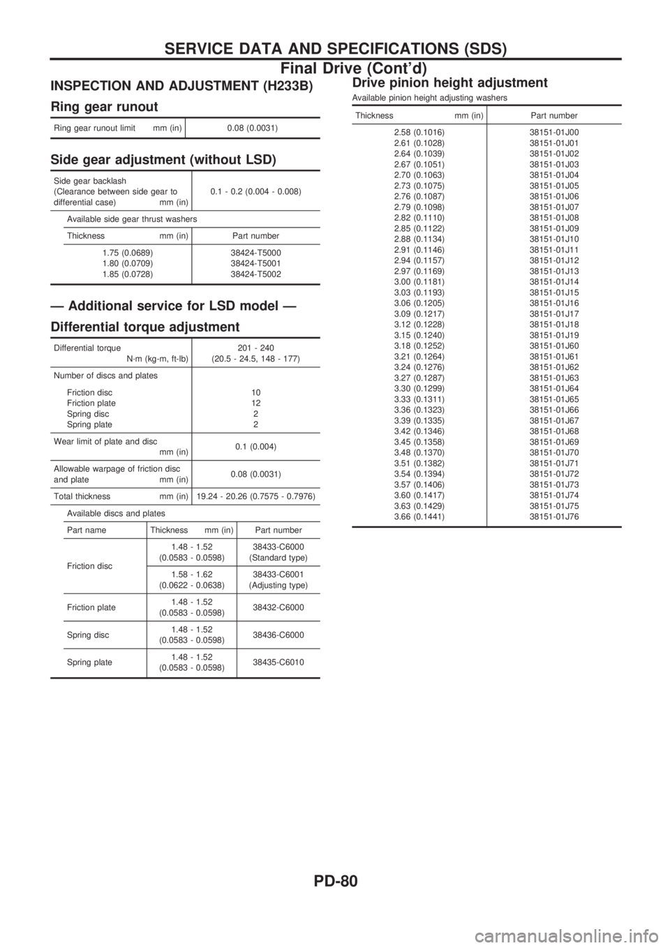
INSPECTION AND ADJUSTMENT (H233B)
Ring gear runout
Ring gear runout limit mm (in) 0.08 (0.0031)
Side gear adjustment (without LSD)
Side gear backlash
(Clearance between side gear to
differential case) mm (in)0.1 - 0.2 (0.004 - 0.008)
Available side gear thrust washers
Thickness mm (in) Part number
1.75 (0.0689)
1.80 (0.0709)
1.85 (0.0728)38424-T5000
38424-T5001
38424-T5002
Ð Additional service for LSD model Ð
Differential torque adjustment
Differential torque
N´m (kg-m, ft-lb)201 - 240
(20.5 - 24.5, 148 - 177)
Number of discs and plates
Friction disc
Friction plate
Spring disc
Spring plate10
12
2
2
Wear limit of plate and disc
mm (in)0.1 (0.004)
Allowable warpage of friction disc
and plate mm (in)0.08 (0.0031)
Total thickness mm (in) 19.24 - 20.26 (0.7575 - 0.7976)
Available discs and plates
Part name Thickness mm (in) Part number
Friction disc1.48 - 1.52
(0.0583 - 0.0598)38433-C6000
(Standard type)
1.58 - 1.62
(0.0622 - 0.0638)38433-C6001
(Adjusting type)
Friction plate1.48 - 1.52
(0.0583 - 0.0598)38432-C6000
Spring disc1.48 - 1.52
(0.0583 - 0.0598)38436-C6000
Spring plate1.48 - 1.52
(0.0583 - 0.0598)38435-C6010
Drive pinion height adjustment
Available pinion height adjusting washers
Thickness mm (in) Part number
2.58 (0.1016)
2.61 (0.1028)
2.64 (0.1039)
2.67 (0.1051)
2.70 (0.1063)
2.73 (0.1075)
2.76 (0.1087)
2.79 (0.1098)
2.82 (0.1110)
2.85 (0.1122)
2.88 (0.1134)
2.91 (0.1146)
2.94 (0.1157)
2.97 (0.1169)
3.00 (0.1181)
3.03 (0.1193)
3.06 (0.1205)
3.09 (0.1217)
3.12 (0.1228)
3.15 (0.1240)
3.18 (0.1252)
3.21 (0.1264)
3.24 (0.1276)
3.27 (0.1287)
3.30 (0.1299)
3.33 (0.1311)
3.36 (0.1323)
3.39 (0.1335)
3.42 (0.1346)
3.45 (0.1358)
3.48 (0.1370)
3.51 (0.1382)
3.54 (0.1394)
3.57 (0.1406)
3.60 (0.1417)
3.63 (0.1429)
3.66 (0.1441)38151-01J00
38151-01J01
38151-01J02
38151-01J03
38151-01J04
38151-01J05
38151-01J06
38151-01J07
38151-01J08
38151-01J09
38151-01J10
38151-01J11
38151-01J12
38151-01J13
38151-01J14
38151-01J15
38151-01J16
38151-01J17
38151-01J18
38151-01J19
38151-01J60
38151-01J61
38151-01J62
38151-01J63
38151-01J64
38151-01J65
38151-01J66
38151-01J67
38151-01J68
38151-01J69
38151-01J70
38151-01J71
38151-01J72
38151-01J73
38151-01J74
38151-01J75
38151-01J76
SERVICE DATA AND SPECIFICATIONS (SDS)
Final Drive (Cont'd)
PD-80
Page 1331 of 1659

Movement ``!''
Compare movement ``!'' in height of pinion when it is pushed out
with magnetic switch energized and when it is pulled out by hand
until it touches stopper.
Movement ``!'':
Refer to SDS, EL-33.
lNot in the specified value ... Adjust by adjusting plate.
Service Data and Specifications (SDS)
STARTER
TypeM3T70381 M3T29482D S13-327
MITSUBISHI HITACHI
Non-reduction Reduction
Applied model2WD 4WD 2WD
KA24 TD25
Standard Standard
System voltage V 12
No-load
Terminal voltage V 11.5 11.0
Current A Less than 60 Less than 160
Revolution rpm More than 6,500 More than 4,000
Minimum diameter of commutator
mm (in)31.4 (1.236) 35.5 (1.398)
Minimum length of brush
mm (in)11.5 (0.453) 9.0 (0.354)
Brush spring tension N (kg, lb)13.7 - 25.5
(1.4 - 2.6, 3.1 - 5.7)Ð
Clearance between bearing metal and
armature shaft
mm (in)Ð Less than 0.2 (0.008) Ð
Clearance ``!'' between pinion front edge
and pinion stopper
mm (in)0.5 - 2.0
(0.020 - 0.079)Ð
Movement ``!'' in height of pinion assembly
mm (in)Ð0.3 - 1.5
(0.012 - 0.059)
SEL497D
SEL633BA
STARTING SYSTEM
Assembly (Cont'd)
EL-33
Page 1581 of 1659
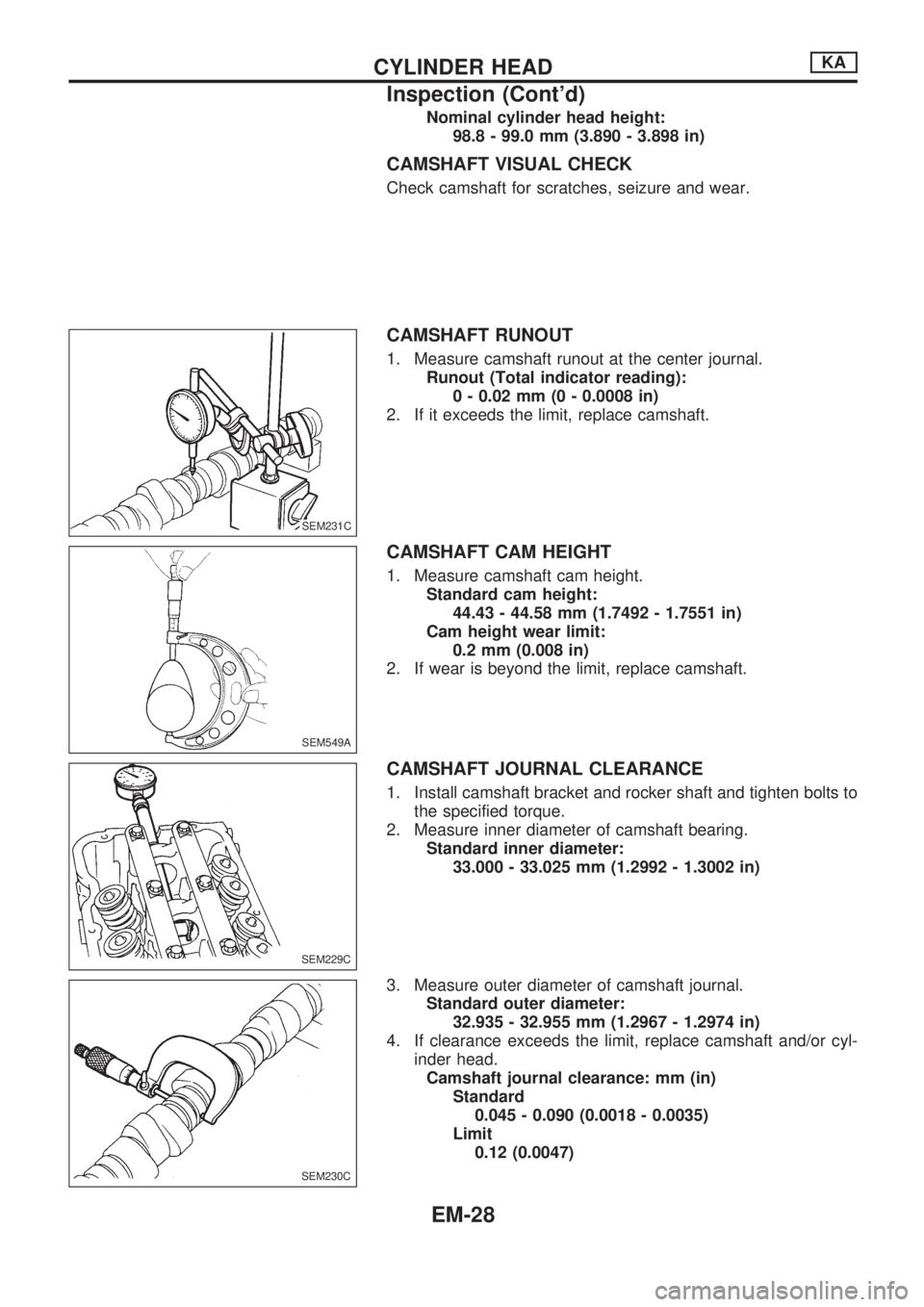
Nominal cylinder head height:
98.8 - 99.0 mm (3.890 - 3.898 in)
CAMSHAFT VISUAL CHECK
Check camshaft for scratches, seizure and wear.
CAMSHAFT RUNOUT
1. Measure camshaft runout at the center journal.
Runout (Total indicator reading):
0 - 0.02 mm (0 - 0.0008 in)
2. If it exceeds the limit, replace camshaft.
CAMSHAFT CAM HEIGHT
1. Measure camshaft cam height.
Standard cam height:
44.43 - 44.58 mm (1.7492 - 1.7551 in)
Cam height wear limit:
0.2 mm (0.008 in)
2. If wear is beyond the limit, replace camshaft.
CAMSHAFT JOURNAL CLEARANCE
1. Install camshaft bracket and rocker shaft and tighten bolts to
the specified torque.
2. Measure inner diameter of camshaft bearing.
Standard inner diameter:
33.000 - 33.025 mm (1.2992 - 1.3002 in)
3. Measure outer diameter of camshaft journal.
Standard outer diameter:
32.935 - 32.955 mm (1.2967 - 1.2974 in)
4. If clearance exceeds the limit, replace camshaft and/or cyl-
inder head.
Camshaft journal clearance: mm (in)
Standard
0.045 - 0.090 (0.0018 - 0.0035)
Limit
0.12 (0.0047)
SEM231C.SEM231C
SEM549A
SEM229C
SEM230C
CYLINDER HEADKA
Inspection (Cont'd)
EM-28
Page 1585 of 1659
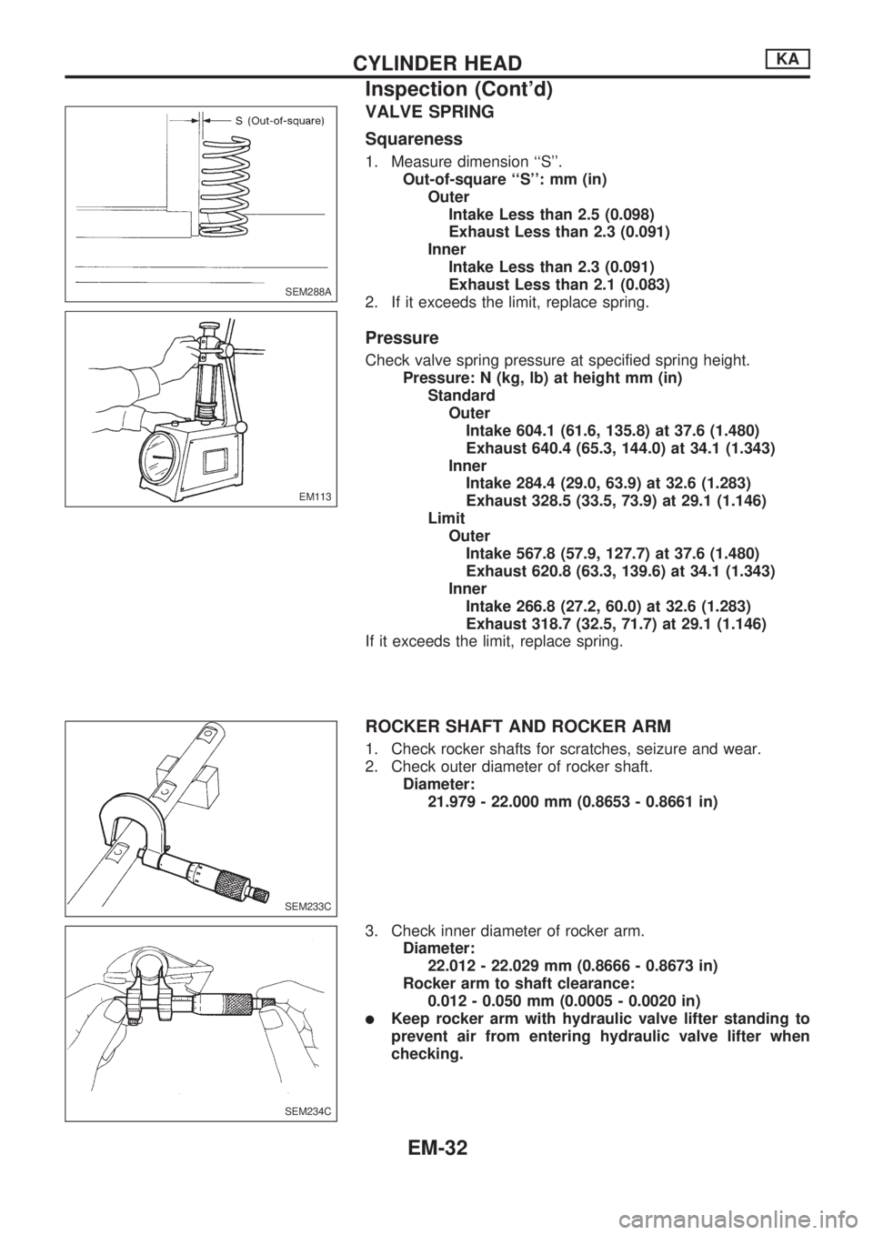
VALVE SPRING
Squareness
1. Measure dimension ``S''.
Out-of-square ``S'': mm (in)
Outer
Intake Less than 2.5 (0.098)
Exhaust Less than 2.3 (0.091)
Inner
Intake Less than 2.3 (0.091)
Exhaust Less than 2.1 (0.083)
2. If it exceeds the limit, replace spring.
Pressure
Check valve spring pressure at specified spring height.
Pressure: N (kg, lb) at height mm (in)
Standard
Outer
Intake 604.1 (61.6, 135.8) at 37.6 (1.480)
Exhaust 640.4 (65.3, 144.0) at 34.1 (1.343)
Inner
Intake 284.4 (29.0, 63.9) at 32.6 (1.283)
Exhaust 328.5 (33.5, 73.9) at 29.1 (1.146)
Limit
Outer
Intake 567.8 (57.9, 127.7) at 37.6 (1.480)
Exhaust 620.8 (63.3, 139.6) at 34.1 (1.343)
Inner
Intake 266.8 (27.2, 60.0) at 32.6 (1.283)
Exhaust 318.7 (32.5, 71.7) at 29.1 (1.146)
If it exceeds the limit, replace spring.
ROCKER SHAFT AND ROCKER ARM
1. Check rocker shafts for scratches, seizure and wear.
2. Check outer diameter of rocker shaft.
Diameter:
21.979 - 22.000 mm (0.8653 - 0.8661 in)
3. Check inner diameter of rocker arm.
Diameter:
22.012 - 22.029 mm (0.8666 - 0.8673 in)
Rocker arm to shaft clearance:
0.012 - 0.050 mm (0.0005 - 0.0020 in)
lKeep rocker arm with hydraulic valve lifter standing to
prevent air from entering hydraulic valve lifter when
checking.
SEM288A
EM113
SEM233C
SEM234C
CYLINDER HEADKA
Inspection (Cont'd)
EM-32
Page 1594 of 1659
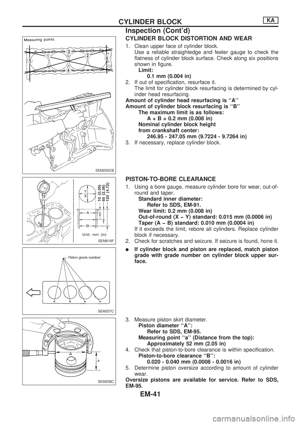
CYLINDER BLOCK DISTORTION AND WEAR
1. Clean upper face of cylinder block.
Use a reliable straightedge and feeler gauge to check the
flatness of cylinder block surface. Check along six positions
shown in figure.
Limit:
0.1 mm (0.004 in)
2. If out of specification, resurface it.
The limit for cylinder block resurfacing is determined by cyl-
inder head resurfacing.
Amount of cylinder head resurfacing is ``A''
Amount of cylinder block resurfacing is ``B''
The maximum limit is as follows:
A+B=0.2mm(0.008 in)
Nominal cylinder block height
from crankshaft center:
246.95 - 247.05 mm (9.7224 - 9.7264 in)
3. If necessary, replace cylinder block.
PISTON-TO-BORE CLEARANCE
1. Using a bore gauge, measure cylinder bore for wear, out-of-
round and taper.
Standard inner diameter:
Refer to SDS, EM-91.
Wear limit: 0.2 mm (0.008 in)
Out-of-round (X þ Y) standard: 0.015 mm (0.0006 in)
Taper (A þ B) standard: 0.010 mm (0.0004 in)
If it exceeds the limit, rebore all cylinders. Replace cylinder
block if necessary.
2. Check for scratches and seizure. If seizure is found, hone it.
lIf cylinder block and piston are replaced, match piston
grade with grade number on cylinder block upper sur-
face.
3. Measure piston skirt diameter.
Piston diameter ``A'':
Refer to SDS, EM-95.
Measuring point ``a'' (Distance from the top):
Approximately 52 mm (2.05 in)
4. Check that piston-to-bore clearance is within specification.
Piston-to-bore clearance ``B'':
0.020 - 0.040 mm (0.0008 - 0.0016 in)
5. Determine piston oversize according to amount of cylinder
wear.
Oversize pistons are available for service. Refer to SDS,
EM-95.
SEM255CB
SEM619F
SEM257C
SEM258C
CYLINDER BLOCKKA
Inspection (Cont'd)
EM-41
Page 1609 of 1659

3. Remove valve oil seals with Tool.
4. Disassemble rocker shaft assembly.
a. Remove rocker shaft lock bolt.
b. Remove valve rocker and rocker shaft bracket.
If it is difficult to remove rocker shaft bracket, immerse
rocker shaft assembly in oil of 70ÉC (158ÉF) for a few min-
utes and then remove bracket.
Inspection
CYLINDER HEAD DISTORTION
Cylinder head distortion: mm (in)
Standard
Less than 0.07 (0.0028)
Limit
0.2 (0.008)
If beyond the specified limit, correct with a surface grinder. Cyl-
inder head height should be greater than 89.7 mm (3.531 in)
after surface has been ground.
VALVE GUIDE CLEARANCE
lValve guide clearance should be measured parallel with
rocker arm. (Generally, a large amount of wear occurs in
this direction.)
Stem to guide clearance: mm (in)
Limit
Intake 0.15 (0.0059)
Exhaust 0.20 (0.0079)
Maximum allowable deflection
(Dial indicator reading)
Intake 0.30 (0.0118)
Exhaust 0.40 (0.0157)
lTo determine the correct replacement part, measure
valve stem diameter and valve guide inner diameter.
Valve stem diameter: mm (in)
Standard
Intake
7.962 - 7.977 (0.3135 - 0.3141)
Exhaust
7.945 - 7.960 (0.3128 - 0.3134)
SEM626BA
SEM627B
SEM648B
SEM586A
EM030
CYLINDER HEADTD
Disassembly (Cont'd)
EM-56
Page 1616 of 1659

Installation
1. Install cylinder head gasket.
Identification of cylinder head gaskets
Identification cut hole
(on cylinder head gas-
ket)Inner diameter
``d'' mm (in)Engine
2 94.4 (3.717) TD25
a. When replacing only cylinder head gasket, install same
grade gasket as the one formerly used.
b. When replacing or repairing cylinder block, cylinder head,
piston, connecting rod and crankshaft, select gasket as fol-
lows:
lSelecting gasket thickness
(1) Measure piston projection from cylinder block surface.
a. Measure the projection a and a¢(cylinder liner height above
cylinder block) at two points in each cylinder.
b. Measure the projection b and b¢(piston height above cylin-
der block) at two points, when the piston is at the top dead
center position.
c. Calculate the piston height projection above cylinder liner b
-a(b¢-a¢).
d. Average the two projections (piston height above cylinder
liner) for each cylinder H
L.
(2) Select suitable cylinder head gasket which conforms to the
largest amount of projection of the four pistons.
Unit: mm (in)
Average values piston projections HL
Gasket thicknessGasket
grade num-
ber New parts In assembly
Less than 0.168 (0.0066)1.35
(0.0531)1.20
(0.0472)2
0.168 - 0.218 (0.0066 - 0.0086)1.40
(0.0551)1.25
(0.0492)3
More than 0.218 (0.0086)1.45
(0.0571)1.30
(0.0512)4
Make sure that No. 1 piston is at TDC on its compression
stroke.
SEM250F
.
DEM036
MEM079A
CYLINDER HEADTD
EM-63