height NISSAN PICK-UP 1998 Service Manual
[x] Cancel search | Manufacturer: NISSAN, Model Year: 1998, Model line: PICK-UP, Model: NISSAN PICK-UP 1998Pages: 1659, PDF Size: 53.39 MB
Page 1106 of 1659

D¢: Figure marked on dummy shaft.
4. Set Tool (Dummy shaft) as shown below and tighten drive
pinion nut carefully to correct preload of 1.1 to 1.4 N´m (11
to 14 kg-cm, 9.5 to 12.2 in-lb).
Tool numbers:
VADummy shaft (KV38100110)
VBCollar (KV38100130)
5. Attach Tool (Height gauge) to gear carrier, and measure the
clearance between the height gauge and the dummy shaft
face.
6. Substitute these values into the equation to calculate the
thickness of the washer.
If values signifying H and D¢are not given, regard them as
zero and calculate.
T (Thickness of washer)=Nþ[(HþD¢) x 0.01] + 3.00
Example:
N = 0.23
H=2
D¢=1
T=Nþ[(HþD¢) x 0.01] + 3.00
= 0.23 þ [(2 þ 1) x 0.01] + 3.00
(1) H ................................................................. 2
þD¢.............................................................. þ1
+1
(2) +1
x 0.01
+0.01
(3) N ............................................................ 0.23
þ (+0.01)
0.22
(4) 0.22
+3.00
3.22
\T = 3.22
7. Select the proper pinion height washer.
Drive pinion height adjusting washer:
Refer to SDS, PD-78.
If you cannot find the desired thickness of washer, use
washer with thickness closest to the calculated value.
Example:
Calculated value ... T = 3.22 mm
Used washer ... T = 3.21 mm
SPD596
SPD597
SPD030A
ADJUSTMENTR180A
Drive Pinion Height (Cont'd)
PD-25
Page 1110 of 1659

2. Select drive pinion bearing adjusting washer and drive pin-
ion height adjusting washer. Refer to ``ADJUSTMENT'',
PD-24.
3. Install drive pinion height adjusting washer in drive pinion,
and press-fit pinion rear bearing inner cone in it, using press
and Tool.
Tool number: ST30901000
4. Place pinion front bearing inner cone in final drive housing.
5. Apply multi-purpose grease to cavity at sealing lips of oil
seal. Install front oil seal.
Tool number: ST30720000
6. Place drive pinion bearing spacer, pinion bearing adjusting
washer and drive pinion in final drive housing.
7. Insert companion flange into drive pinion by tapping the com-
panion flange with a soft hammer.
8. Tighten pinion nut to the specified torque.
The threaded portion of drive pinion and pinion nut should
be free from oil or grease.
Tool number: ST38060002
SPD377
SPD657
SPD658
SPD659
PD466
ASSEMBLYR180A
Final Drive Housing (Cont'd)
PD-29
Page 1117 of 1659

7. Remove sensor rotor with Tools (With ABS models).
Tool numbers:
VAST33061000
VBST30031000
8. Remove ABS sensor unit.
9. Remove drive pinion with soft hammer.
10. Remove front oil seal and pinion front bearing inner cone.
11. Remove pinion bearing outer races with a brass drift.
12. Remove pinion rear bearing inner cone and pinion height
adjusting washer.
Tool number: ST30031000
SPD430A
SPD206
PD349
PD179
DISASSEMBLYC200
Differential Carrier (Cont'd)
PD-36
Page 1126 of 1659

For quiet and reliable final drive operation, the following five
adjustments must be made correctly.
1. Side bearing preload
2. Pinion gear height
3. Pinion bearing preload. Refer to ``ASSEMBLY'', PD-53.
4. Ring gear-to-pinion backlash. Refer to ``ASSEMBLY'',
PD-54.
5. Ring and pinion gear tooth contact pattern
Side Bearing Preload
A selection of carrier side bearing preload shims is required
for successful completion of this procedure.
1. Make sure all parts are clean. Make sure, also, the bearings
are well lubricated with light oil or type ``DEXRON
TM'' auto-
matic transmission fluid.
2. Place the differential carrier, with side bearings and bearing
races installed, into the final drive housing.
3. Put the side bearing spacer in place.
CAUTION:
Side bearing spacer is placed on either the right or left
depending upon final drive gear ratio. Be sure to replace it
on the correct side.
4. Use Tool to place original carrier side bearing preload shims
on the carrier end, opposite the ring gear.
Tool number: KV38100600
SPD919
SPD894
SPD986
ADJUSTMENTC200
PD-45
Page 1128 of 1659

Drive Pinion Height
1. Prepare Tools for pinion height adjustment.
V1Dummy Shaft (KV38103910)
V2Height Gauge (KV38100120)
V3Stopper (KV38100140)
V4Feeler Gauge
2. To simplify the job, make a chart, like the one below, to
organize your calculations.
LETTERS HUNDREDTHS OF A MILLIMETER
H: Head number
N: Measuring clearance
3. Write the following numbers down the chart.
H: Head number
4. Set Tool (Dummy shaft) as shown at left and tighten drive
pinion nut carefully to correct preload of 1.0 to 1.3 N´m (10
to 13 kg-cm, 8.7 to 11.3 in-lb).
Tool number: KV38103910
SPD233
SPD542
SPD756
ADJUSTMENTC200
PD-47
Page 1129 of 1659

5. Attach Tool (Height gauge) to gear carrier, and measure the
clearance ``N'' between the height gauge and the dummy
shaft face.
Tool number: KV38100120
6. Substitute these values into the equation to calculate the
thickness of the washer.
If value signifying H is not given, regard it as zero and cal-
culate.
T (Thickness of washer)=Nþ(Hx0.01) + 3.00
Example:
N = 0.23
H=1
T=Nþ(Hx0.01) + 3.00 = 0.23 þ (1 x 0.01) + 3.00
(1) H ................................................................. 1
x 0.01
+0.01
(2) N ............................................................ 0.23
þ (+0.01)
0.22
(3) 0.22
+3.00
3.22
\T = 3.22
7. Select the proper washer. (Refer to SDS.)
If you cannot find the desired thickness of washer, use
washer with thickness closest to the calculated value.
Example:
Calculated value ... T = 3.22 mm
Used washer ... T = 3.21 mm
SPD757
ADJUSTMENTC200
Drive Pinion Height (Cont'd)
PD-48
Page 1132 of 1659
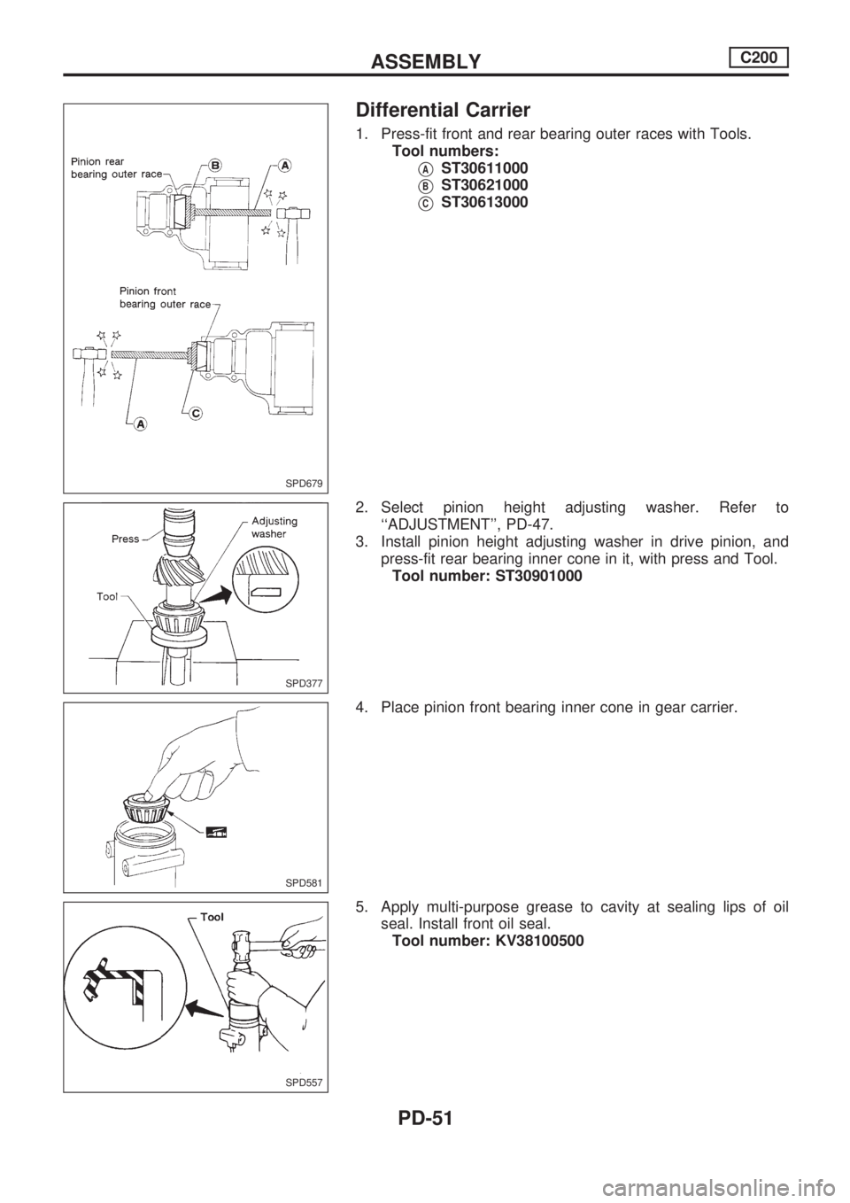
Differential Carrier
1. Press-fit front and rear bearing outer races with Tools.
Tool numbers:
VAST30611000
VBST30621000
VCST30613000
2. Select pinion height adjusting washer. Refer to
``ADJUSTMENT'', PD-47.
3. Install pinion height adjusting washer in drive pinion, and
press-fit rear bearing inner cone in it, with press and Tool.
Tool number: ST30901000
4. Place pinion front bearing inner cone in gear carrier.
5. Apply multi-purpose grease to cavity at sealing lips of oil
seal. Install front oil seal.
Tool number: KV38100500
SPD679
SPD377
SPD581
SPD557
ASSEMBLYC200
PD-51
Page 1148 of 1659
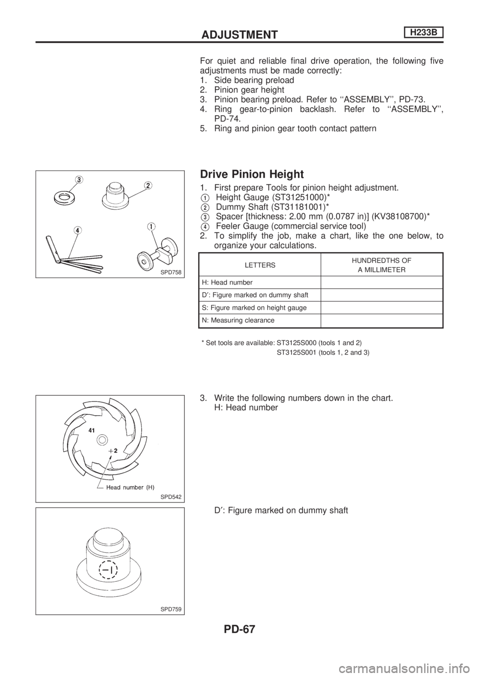
For quiet and reliable final drive operation, the following five
adjustments must be made correctly:
1. Side bearing preload
2. Pinion gear height
3. Pinion bearing preload. Refer to ``ASSEMBLY'', PD-73.
4. Ring gear-to-pinion backlash. Refer to ``ASSEMBLY'',PD-74.
5. Ring and pinion gear tooth contact pattern
Drive Pinion Height
1.FirstprepareToolsforpinionheightadjustment.
V1HeightGauge(ST31251000)*
V2DummyShaft(ST31181001)*
V3Spacer[thickness:2.00mm(0.0787 in)] (KV38108700)*
V4FeelerGauge (commercial service tool)
2. To simplify the job, make a chart, like the one below, to organize your calculations.
LETTERS HUNDREDTHS OF
A MILLIMETER
H: Head number
D ¢: Figure marked on dummy shaft
S: Figure marked on height gauge
N:Measuringclearance
* Set tools are available: ST3125S000 (tools 1 and 2) ST3125S001 (tools 1, 2 and 3)
3. Write the following numbers down in the chart.H: Head number
D¢: Figure marked on dummy shaft
SPD758
SPD542
SPD759
ADJUSTMENTH233B
PD-67
Page 1149 of 1659
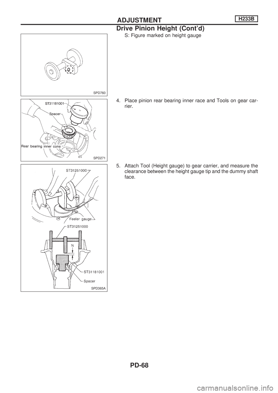
S: Figure marked on height gauge
4. Place pinion rear bearing inner race and Tools on gear car-
rier.
5. Attach Tool (Height gauge) to gear carrier, and measure the
clearance between the height gauge tip and the dummy shaft
face.
SPD760
SPD271
SPD365A
ADJUSTMENTH233B
Drive Pinion Height (Cont'd)
PD-68
Page 1150 of 1659
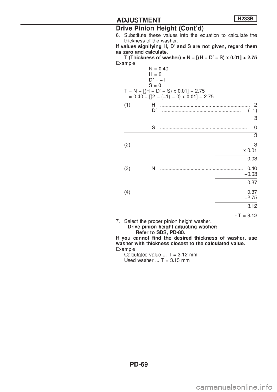
6. Substitute these values into the equation to calculate thethickness of the washer.
If values signifying H, D ¢and S are not given, regard them
as zero and calculate. T(Thicknessofwasher )=Nþ[(HþD¢þS)x0.01]+2.75
Example: N=0.40
H=2
D¢=þ1
S=0
T=Nþ[(HþD ¢þS)x0.01]+2.75
=0.40þ[{2þ(þ1)þ0}x0.01]+2.75
(1) H ................................................................. 2 þD¢ ......................................................... þ(þ1)
3
þS ............................................................... þ0
3
(2) 3 x 0.01
0.03
(3)N............................................................0.40 þ0.03
0.37
(4)0.37 +2.75
3.12
\ T=3.12
7. Select the proper pinion height washer. Drive pinion height adjusting washer:Refer to SDS, PD-80.
If you cannot find the desired thickness of washer, use
washer with thickness closest to the calculated value.
Example: Calculatedvalue.. .T=3.12mm
Usedwasher.. .T=3.13mm
ADJUSTMENTH233B
Drive Pinion Height (Cont'd)
PD-69