check oil NISSAN PICK-UP 1998 Workshop Manual
[x] Cancel search | Manufacturer: NISSAN, Model Year: 1998, Model line: PICK-UP, Model: NISSAN PICK-UP 1998Pages: 1659, PDF Size: 53.39 MB
Page 913 of 1659
VA
Note
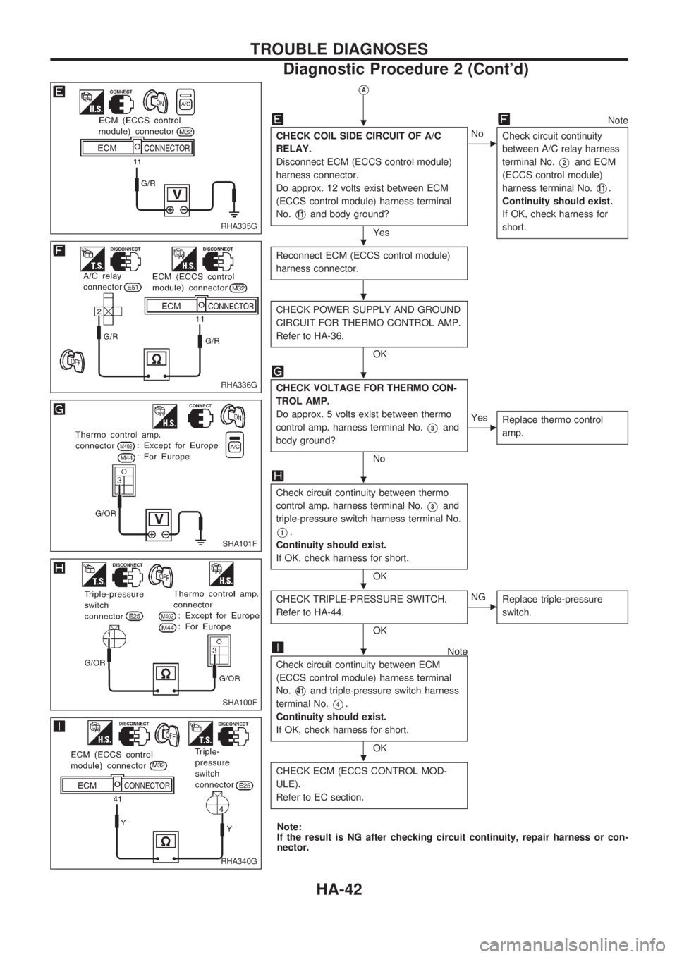
CHECK COIL SIDE CIRCUIT OF A/C
RELAY.
Disconnect ECM (ECCS control module)
harness connector.
Do approx. 12 volts exist between ECM
(ECCS control module) harness terminal
No.
V11and body ground?
Yes
cNo
Check circuit continuity
between A/C relay harness
terminal No.
V2and ECM
(ECCS control module)
harness terminal No.
V11.
Continuity should exist.
If OK, check harness for
short.
Reconnect ECM (ECCS control module)
harness connector.
CHECK POWER SUPPLY AND GROUND
CIRCUIT FOR THERMO CONTROL AMP.
Refer to HA-36.
OK
CHECK VOLTAGE FOR THERMO CON-
TROL AMP.
Do approx. 5 volts exist between thermo
control amp. harness terminal No.
V3and
body ground?
No
cYes
Replace thermo control
amp.
Check circuit continuity between thermo
control amp. harness terminal No.
V3and
triple-pressure switch harness terminal No.
V1.
Continuity should exist.
If OK, check harness for short.
OK
CHECK TRIPLE-PRESSURE SWITCH.
Refer to HA-44.
OK
cNG
Replace triple-pressure
switch.
Note
Check circuit continuity between ECM
(ECCS control module) harness terminal
No.
V41and triple-pressure switch harness
terminal No.
V4.
Continuity should exist.
If OK, check harness for short.
OK
CHECK ECM (ECCS CONTROL MOD-
ULE).
Refer to EC section.
Note:
If the result is NG after checking circuit continuity, repair harness or con-
nector.
RHA335G
RHA336G
SHA101F
SHA100F
RHA340G
.
.
.
.
.
.
.
.
TROUBLE DIAGNOSES
Diagnostic Procedure 2 (Cont'd)
HA-42
Page 921 of 1659
Maintenance of Lubricant Quantity in
Compressor
The lubricant used to lubricate the compressor circulates through
the system with the refrigerant. Add lubricant to compressor
when replacing any component or after a large gas leakage
occurred. It is important to maintain the specified amount.
If lubricant quantity is not maintained properly, the following mal-
functions may result:
lLack of lubricant: May lead to a seized compressor
lExcessive lubricant: Inadequate cooling (thermal exchange
interference)
LUBRICANT
Name: Nissan A/C System Oil Type R
Part number: KLH00-PAGR0
CHECKING AND ADJUSTING
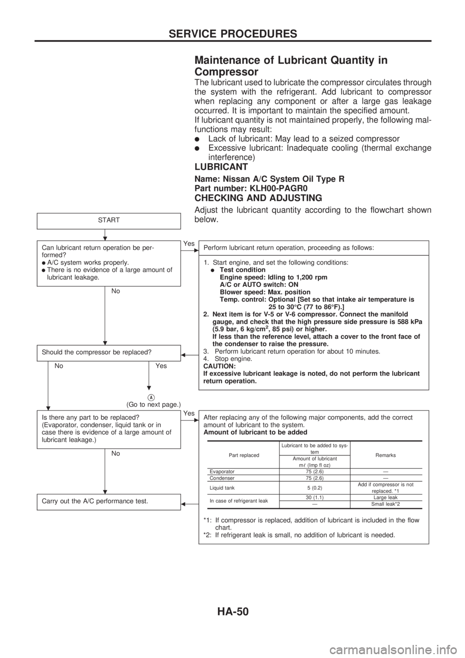
Adjust the lubricant quantity according to the flowchart shown
below.
START
Can lubricant return operation be per-
formed?
lA/C system works properly.lThere is no evidence of a large amount of
lubricant leakage.
No
cYes
Perform lubricant return operation, proceeding as follows:
-----------------------------------------------------------------------------------------------------------------------------------------------------------------------------------------------------------------------------------------------------------------------------------------------------------------------------------------------------------------------------------------------------------------------------------------------------------------------------------------------------------------------------------
1. Start engine, and set the following conditions:
lTest condition
Engine speed: Idling to 1,200 rpm
A/C or AUTO switch: ON
Blower speed: Max. position
Temp. control: Optional [Set so that intake air temperature is
25 to 30ÉC (77 to 86ÉF).]
2. Next item is for V-5 or V-6 compressor. Connect the manifold
gauge, and check that the high pressure side pressure is 588 kPa
(5.9 bar, 6 kg/cm
2, 85 psi) or higher.
If less than the reference level, attach a cover to the front face of
the condenser to raise the pressure.
3. Perform lubricant return operation for about 10 minutes.
4. Stop engine.
CAUTION:
If excessive lubricant leakage is noted, do not perform the lubricant
return operation.
Should the compressor be replaced?
No Yes
b
VA(Go to next page.)
Is there any part to be replaced?
(Evaporator, condenser, liquid tank or in
case there is evidence of a large amount of
lubricant leakage.)
No
cYes
After replacing any of the following major components, add the correct
amount of lubricant to the system.
Amount of lubricant to be added
*1: If compressor is replaced, addition of lubricant is included in the flow
chart.
*2: If refrigerant leak is small, no addition of lubricant is needed.
Carry out the A/C performance test.b
Part replacedLubricant to be added to sys-
tem
Remarks
Amount of lubricant
m!(Imp fl oz)
Evaporator 75 (2.6) Ð
Condenser 75 (2.6) Ð
Liquid tank 5 (0.2)Add if compressor is not
replaced. *1
In case of refrigerant leak30 (1.1) Large leak
Ð Small leak*2
.
.
.
.
.
SERVICE PROCEDURES
HA-50
Page 932 of 1659
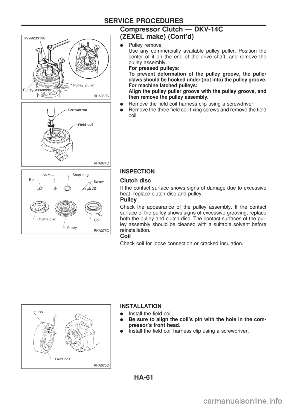
lPulley removal
Use any commercially available pulley puller. Position the
center of it on the end of the drive shaft, and remove the
pulley assembly.
For pressed pulleys:
To prevent deformation of the pulley groove, the puller
claws should be hooked under (not into) the pulley groove.
For machine latched pulleys:
Align the pulley puller groove with the pulley groove, and
then remove the pulley assembly.
lRemove the field coil harness clip using a screwdriver.
lRemove the three field coil fixing screws and remove the field
coil.
INSPECTION
Clutch disc
If the contact surface shows signs of damage due to excessive
heat, replace clutch disc and pulley.
Pulley
Check the appearance of the pulley assembly. If the contact
surface of the pulley shows signs of excessive grooving, replace
both the pulley and clutch disc. The contact surfaces of the pul-
ley assembly should be cleaned with a suitable solvent before
reinstallation.
Coil
Check coil for loose connection or cracked insulation.
INSTALLATION
lInstall the field coil.
lBe sure to align the coil's pin with the hole in the com-
pressor's front head.
lInstall the field coil harness clip using a screwdriver.
RHA368G
RHA074C
RHA075C
RHA076C
SERVICE PROCEDURES
Compressor Clutch Ð DKV-14C
(ZEXEL make) (Cont'd)
HA-61
Page 936 of 1659
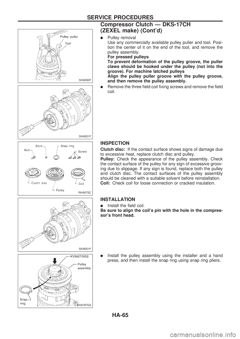
lPulley removal
Use any commercially available pulley puller and tool. Posi-
tion the center of it on the end of the tool, and remove the
pulley assembly.
For pressed pulleys
To prevent deformation of the pulley groove, the puller
claws should be hooked under the pulley (not into the
groove). For machine latched pulleys
Align the pulley puller groove with the pulley groove,
and then remove the pulley assembly.
lRemove the three field coil fixing screws and remove the field
coil.
INSPECTION
Clutch disc:If the contact surface shows signs of damage due
to excessive heat, replace clutch disc and pulley.
Pulley:Check the appearance of the pulley assembly. Check
the contact surface of the pulley for any sign of excessive groov-
ing due to slippage. If any sign is found, replace both the pulley
and clutch disc. The contact surfaces of the pulley assembly
should be cleaned with a suitable solvent before reinstallation.
Coil:Check coil for loose connection or cracked insulation.
INSTALLATION
lInstall the field coil.
Be sure to align the coil's pin with the hole in the compres-
sor's front head.
lInstall the pulley assembly using the installer and a hand
press, and then install the snap ring using snap ring pliers.
SHA050F
SHA051F
RHA075C
SHA051F
SHA797EA
SERVICE PROCEDURES
Compressor Clutch Ð DKS-17CH
(ZEXEL make) (Cont'd)
HA-65
Page 939 of 1659
ENGINE LUBRICATION &
COOLING SYSTEMS
SECTION
LC
CONTENTS
PRECAUTIONS AND PREPARATION..................... 1
Liquid Gasket Application Procedure .................... 1
Special Service Tools ............................................ 2
KA
ENGINE LUBRICATION SYSTEM............................ 3
Lubrication Circuit .................................................. 3
Oil Pressure Check ................................................ 4
Oil Pump ................................................................ 4
ENGINE COOLING SYSTEM.................................... 6
Cooling Circuit........................................................ 6
System Check ........................................................ 6
Water Pump ........................................................... 7
Thermostat ............................................................. 8
Radiator.................................................................. 9
Cooling Fan (Crankshaft driven).......................... 10
TD
ENGINE LUBRICATION SYSTEM.......................... 12
Lubrication Circuit ................................................ 12
Oil Pressure Check (On-vehicle service) ............ 13
Oil Pump .............................................................. 14
Oil Filter Bracket .................................................. 16
Oil Cooler ............................................................. 17Oil Jet ................................................................... 18
ENGINE COOLING SYSTEM.................................. 19
Cooling Circuit...................................................... 19
Cooling System Inspection .................................. 20
Water Pump and Cooling Fan (Camshaft
driven) .................................................................. 21
Thermostat ........................................................... 23
Radiator................................................................ 24
Refilling Engine Coolant ...................................... 24
ENGINE ROOM FAN MOTOR ELECTRICAL
CIRCUIT................................................................... 25
Wiring Diagram .................................................... 25
Cooling Fan (Motor driven) .................................. 26
Electrical Components Inspection ....................... 26
ENGINE COOLING SYSTEM.................................. 28
Radiator (Aluminum type) .................................... 28
Overheating Cause Analysis ............................... 31
SERVICE DATA AND SPECIFICATIONS (SDS)... 32
Engine Lubrication System (KA).......................... 32
Engine Cooling System (KA) ............................... 32
Engine Lubrication System (TD).......................... 32
Engine Cooling System (TD) ............................... 32
LC
Page 943 of 1659

Oil Pressure Check
WARNING:
lBe careful not to burn yourself, as the engine and oil
may be hot.
lPut gearshift lever in Neutral N position.
1. Check oil level.
2. Remove oil pressure switch.
3. Install pressure gauge.
4. Start engine and warm it up to normal operating temperature.
5. Check oil pressure with engine running under no-load.
Engine speed
rpmApproximate discharge pressure
kPa (bar, kg/cm2, psi)
Idle speed More than 78 (0.78, 0.8, 11)
3,000 412 - 481 (4.12 - 4.81, 4.2 - 4.9, 60 - 70)
lIf difference is extreme, check oil passage and oil pump
for oil leaks.
6. Install oil pressure switch with sealant.
Oil Pump
SLC183A
SLC770A
SLC229B
ENGINE LUBRICATION SYSTEMKA
LC-4
Page 944 of 1659

lAlways replace with new oil seal and gasket.
lWhen removing oil pump, turn crankshaft so that No. 1
piston is at TDC on its compression stroke.
lWhen installing oil pump, apply engine oil to gears, then
align punchmark on drive spindle and oil hole on oil
pump.
REGULATOR VALVE INSPECTION
1. Visually inspect components for wear and damage.
2. Check oil pressure regulator valve sliding surface and valve
spring.
3. Coat regulator valve with engine oil. Check that it falls
smoothly into the valve hole by its own weight.
lReplace regulator valve set or oil pump assembly, if
damaged.
OIL PRESSURE RELIEF VALVE INSPECTION
Inspect oil pressure relief valve for movement, cracks and breaks
by pushing the ball. If replacement is necessary, remove valve
by prying it out with suitable tool.
Install a new valve by tapping it in place.
OIL PUMP INSPECTION
Using a feeler gauge, check the following clearance.
Standard clearance:
Unit: mm (in)
Rotor tip clearanceV1Less than 0.12 (0.0047)
Outer rotor to body radial clearance
V20.15 - 0.21 (0.0059 - 0.0083)
Side clearance (with gasket)
V30.04 - 0.08 (0.0016 - 0.0031)
lIf the tip clearance (V1) exceeds the limit, replace rotor
set.
lIf body to rotor clearances (V2,V3) exceed the limit,
replace oil pump assembly.
SLC133B
ALC058
SLC185A
SLC026
SLC732
ENGINE LUBRICATION SYSTEMKA
Oil Pump (Cont'd)
LC-5
Page 950 of 1659
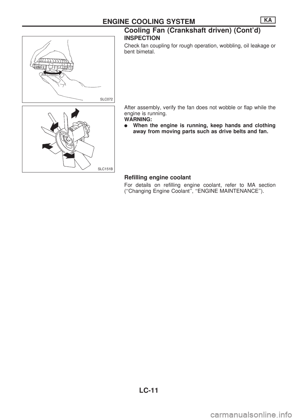
INSPECTION
Check fan coupling for rough operation, wobbling, oil leakage or
bent bimetal.
After assembly, verify the fan does not wobble or flap while the
engine is running.
WARNING:
lWhen the engine is running, keep hands and clothing
away from moving parts such as drive belts and fan.
Refilling engine coolant
For details on refilling engine coolant, refer to MA section
(``Changing Engine Coolant'', ``ENGINE MAINTENANCE'').
SLC072
SLC151B
ENGINE COOLING SYSTEMKA
Cooling Fan (Crankshaft driven) (Cont'd)
LC-11
Page 952 of 1659
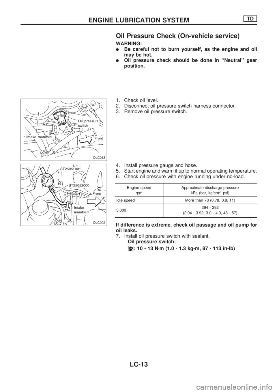
Oil Pressure Check (On-vehicle service)
WARNING:
lBe careful not to burn yourself, as the engine and oil
may be hot.
lOil pressure check should be done in ``Neutral'' gear
position.
1. Check oil level.
2. Disconnect oil pressure switch harness connector.
3. Remove oil pressure switch.
4. Install pressure gauge and hose.
5. Start engine and warm it up to normal operating temperature.
6. Check oil pressure with engine running under no-load.
Engine speed
rpmApproximate discharge pressure
kPa (bar, kg/cm2, psi)
Idle speed More than 78 (0.78, 0.8, 11)
3,000294 - 392
(2.94 - 3.92, 3.0 - 4.0, 43 - 57)
If difference is extreme, check oil passage and oil pump for
oil leaks.
7. Install oil pressure switch with sealant.
Oil pressure switch:
:10-13Nzm (1.0 - 1.3 kg-m, 87 - 113 in-lb)
DLC013
DLC002
ENGINE LUBRICATION SYSTEMTD
LC-13
Page 953 of 1659
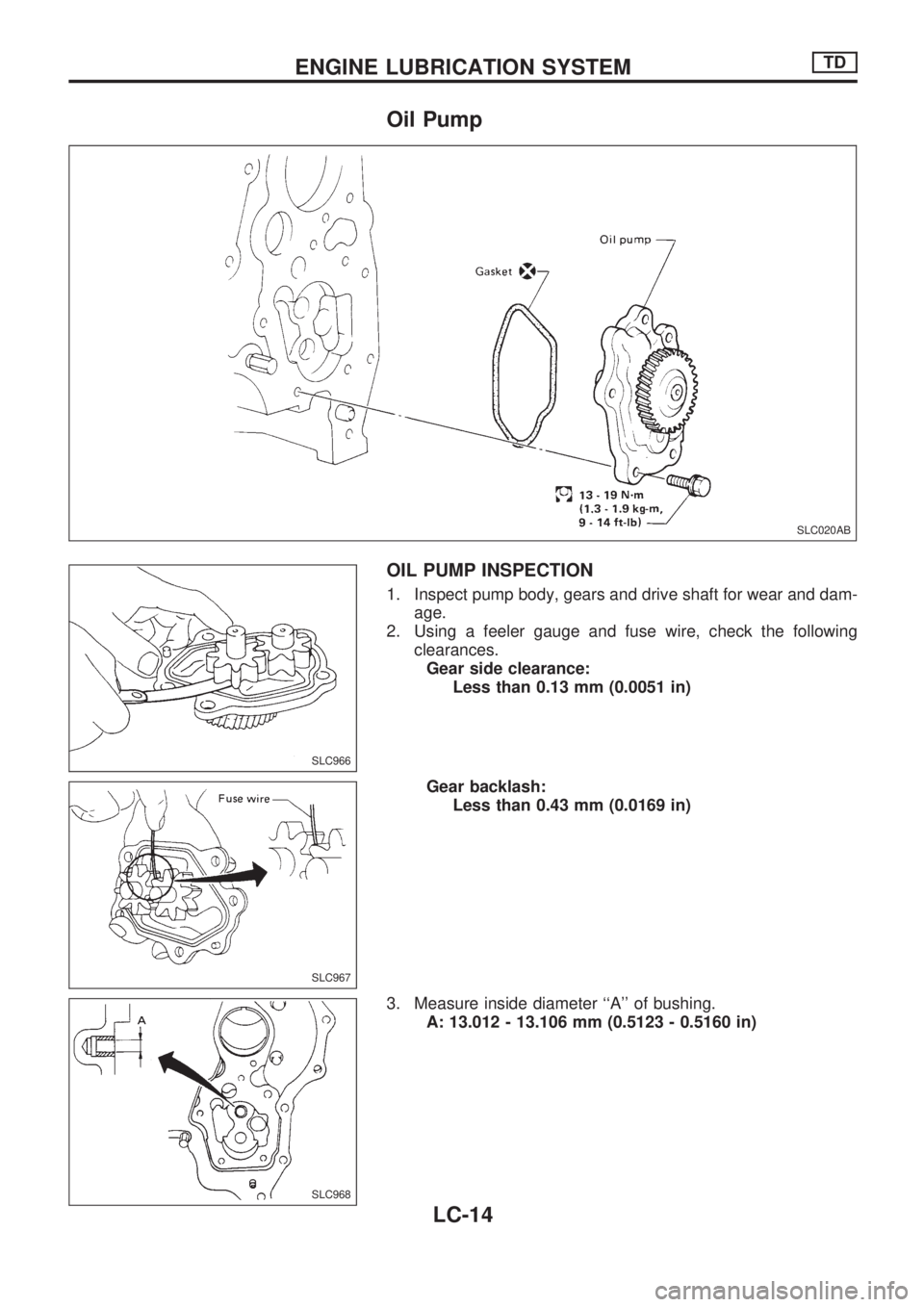
Oil Pump
OIL PUMP INSPECTION
1. Inspect pump body, gears and drive shaft for wear and dam-
age.
2. Using a feeler gauge and fuse wire, check the following
clearances.
Gear side clearance:
Less than 0.13 mm (0.0051 in)
Gear backlash:
Less than 0.43 mm (0.0169 in)
3. Measure inside diameter ``A'' of bushing.
A: 13.012 - 13.106 mm (0.5123 - 0.5160 in)
SLC020AB
SLC966
SLC967
SLC968
ENGINE LUBRICATION SYSTEMTD
LC-14