fuel pump NISSAN PICK-UP 1998 Repair Manual
[x] Cancel search | Manufacturer: NISSAN, Model Year: 1998, Model line: PICK-UP, Model: NISSAN PICK-UP 1998Pages: 1659, PDF Size: 53.39 MB
Page 151 of 1659
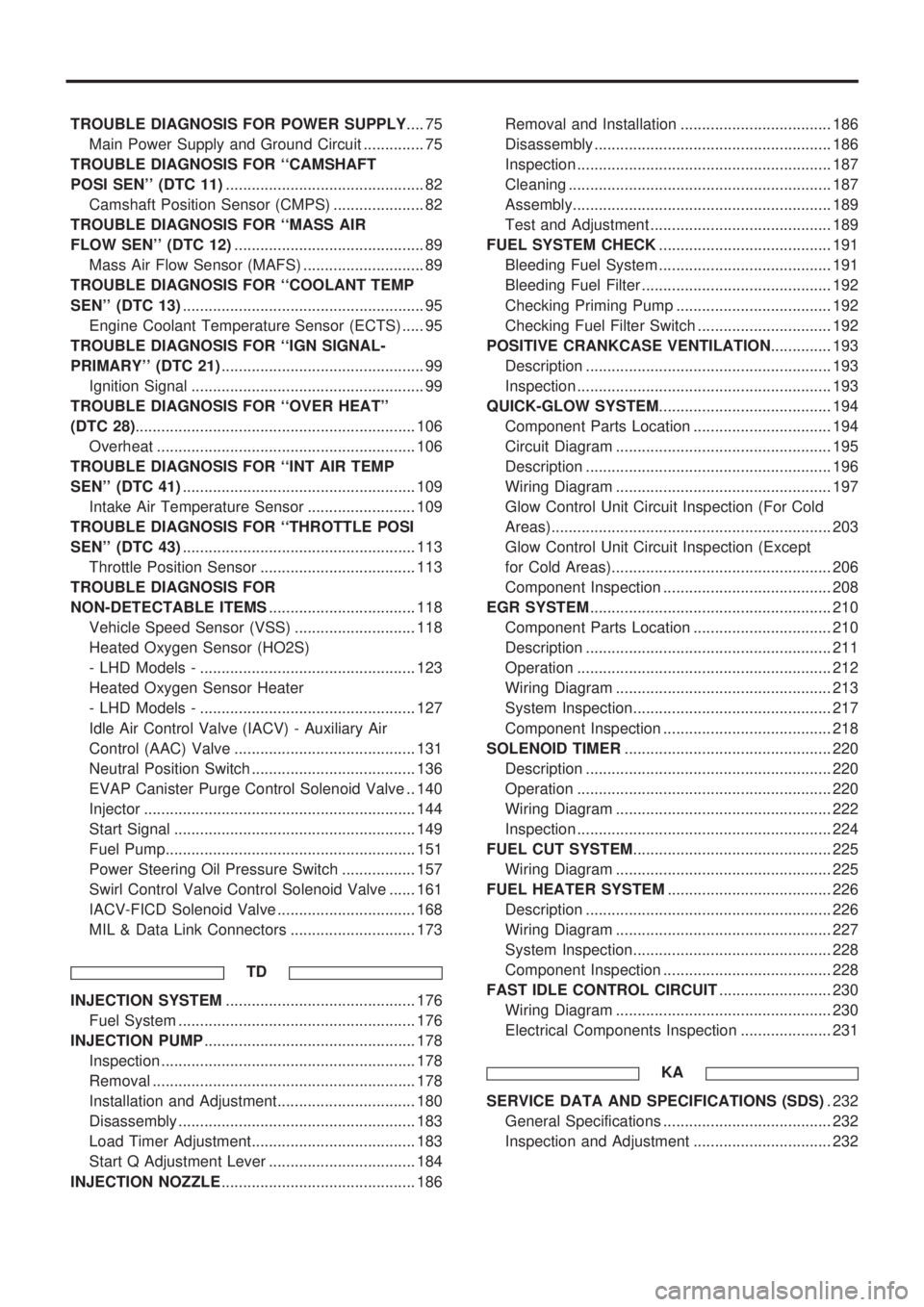
TROUBLE DIAGNOSIS FOR POWER SUPPLY.... 75
Main Power Supply and Ground Circuit .............. 75
TROUBLE DIAGNOSIS FOR ``CAMSHAFT
POSI SEN'' (DTC 11).............................................. 82
Camshaft Position Sensor (CMPS) ..................... 82
TROUBLE DIAGNOSIS FOR ``MASS AIR
FLOW SEN'' (DTC 12)............................................ 89
Mass Air Flow Sensor (MAFS) ............................ 89
TROUBLE DIAGNOSIS FOR ``COOLANT TEMP
SEN'' (DTC 13)........................................................ 95
Engine Coolant Temperature Sensor (ECTS) ..... 95
TROUBLE DIAGNOSIS FOR ``IGN SIGNAL-
PRIMARY'' (DTC 21)............................................... 99
Ignition Signal ...................................................... 99
TROUBLE DIAGNOSIS FOR ``OVER HEAT''
(DTC 28)................................................................. 106
Overheat ............................................................ 106
TROUBLE DIAGNOSIS FOR ``INT AIR TEMP
SEN'' (DTC 41)...................................................... 109
Intake Air Temperature Sensor ......................... 109
TROUBLE DIAGNOSIS FOR ``THROTTLE POSI
SEN'' (DTC 43)...................................................... 113
Throttle Position Sensor .................................... 113
TROUBLE DIAGNOSIS FOR
NON-DETECTABLE ITEMS.................................. 118
Vehicle Speed Sensor (VSS) ............................ 118
Heated Oxygen Sensor (HO2S)
- LHD Models - .................................................. 123
Heated Oxygen Sensor Heater
- LHD Models - .................................................. 127
Idle Air Control Valve (IACV) - Auxiliary Air
Control (AAC) Valve .......................................... 131
Neutral Position Switch ...................................... 136
EVAP Canister Purge Control Solenoid Valve .. 140
Injector ............................................................... 144
Start Signal ........................................................ 149
Fuel Pump.......................................................... 151
Power Steering Oil Pressure Switch ................. 157
Swirl Control Valve Control Solenoid Valve ...... 161
IACV-FICD Solenoid Valve ................................ 168
MIL & Data Link Connectors ............................. 173
TD
INJECTION SYSTEM............................................ 176
Fuel System ....................................................... 176
INJECTION PUMP................................................. 178
Inspection ........................................................... 178
Removal ............................................................. 178
Installation and Adjustment................................ 180
Disassembly ....................................................... 183
Load Timer Adjustment...................................... 183
Start Q Adjustment Lever .................................. 184
INJECTION NOZZLE............................................. 186Removal and Installation ................................... 186
Disassembly ....................................................... 186
Inspection ........................................................... 187
Cleaning ............................................................. 187
Assembly............................................................ 189
Test and Adjustment .......................................... 189
FUEL SYSTEM CHECK........................................ 191
Bleeding Fuel System ........................................ 191
Bleeding Fuel Filter ............................................ 192
Checking Priming Pump .................................... 192
Checking Fuel Filter Switch ............................... 192
POSITIVE CRANKCASE VENTILATION.............. 193
Description ......................................................... 193
Inspection ........................................................... 193
QUICK-GLOW SYSTEM........................................ 194
Component Parts Location ................................ 194
Circuit Diagram .................................................. 195
Description ......................................................... 196
Wiring Diagram .................................................. 197
Glow Control Unit Circuit Inspection (For Cold
Areas)................................................................. 203
Glow Control Unit Circuit Inspection (Except
for Cold Areas)................................................... 206
Component Inspection ....................................... 208
EGR SYSTEM........................................................ 210
Component Parts Location ................................ 210
Description ......................................................... 211
Operation ........................................................... 212
Wiring Diagram .................................................. 213
System Inspection.............................................. 217
Component Inspection ....................................... 218
SOLENOID TIMER................................................ 220
Description ......................................................... 220
Operation ........................................................... 220
Wiring Diagram .................................................. 222
Inspection ........................................................... 224
FUEL CUT SYSTEM.............................................. 225
Wiring Diagram .................................................. 225
FUEL HEATER SYSTEM...................................... 226
Description ......................................................... 226
Wiring Diagram .................................................. 227
System Inspection.............................................. 228
Component Inspection ....................................... 228
FAST IDLE CONTROL CIRCUIT.......................... 230
Wiring Diagram .................................................. 230
Electrical Components Inspection ..................... 231
KA
SERVICE DATA AND SPECIFICATIONS (SDS). 232
General Specifications ....................................... 232
Inspection and Adjustment ................................ 232
Page 165 of 1659
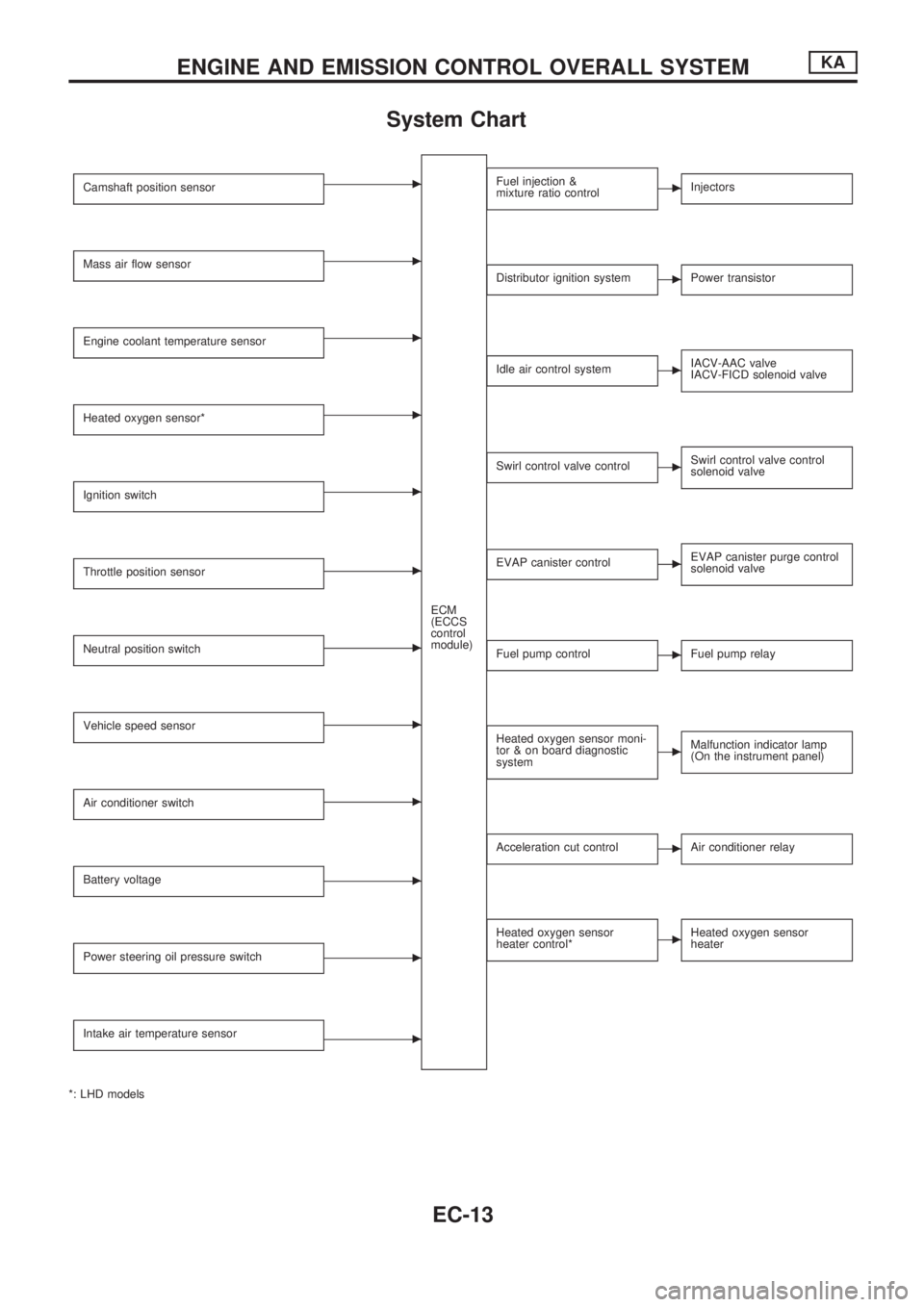
System Chart
Camshaft position sensorc
ECM
(ECCS
control
module)
Mass air flow sensorc
Engine coolant temperature sensorc
Heated oxygen sensor*c
Ignition switchc
Throttle position sensorc
Neutral position switchc
Vehicle speed sensorc
Air conditioner switchc
Battery voltagec
Power steering oil pressure switchc
Intake air temperature sensorc
*: LHD models
Fuel injection &
mixture ratio controlcInjectors
Distributor ignition systemcPower transistor
Idle air control systemcIACV-AAC valve
IACV-FICD solenoid valve
Swirl control valve controlcSwirl control valve control
solenoid valve
EVAP canister controlcEVAP canister purge control
solenoid valve
Fuel pump controlcFuel pump relay
Heated oxygen sensor moni-
tor & on board diagnostic
systemcMalfunction indicator lamp
(On the instrument panel)
Acceleration cut controlcAir conditioner relay
Heated oxygen sensor
heater control*cHeated oxygen sensor
heater
ENGINE AND EMISSION CONTROL OVERALL SYSTEMKA
EC-13
Page 174 of 1659
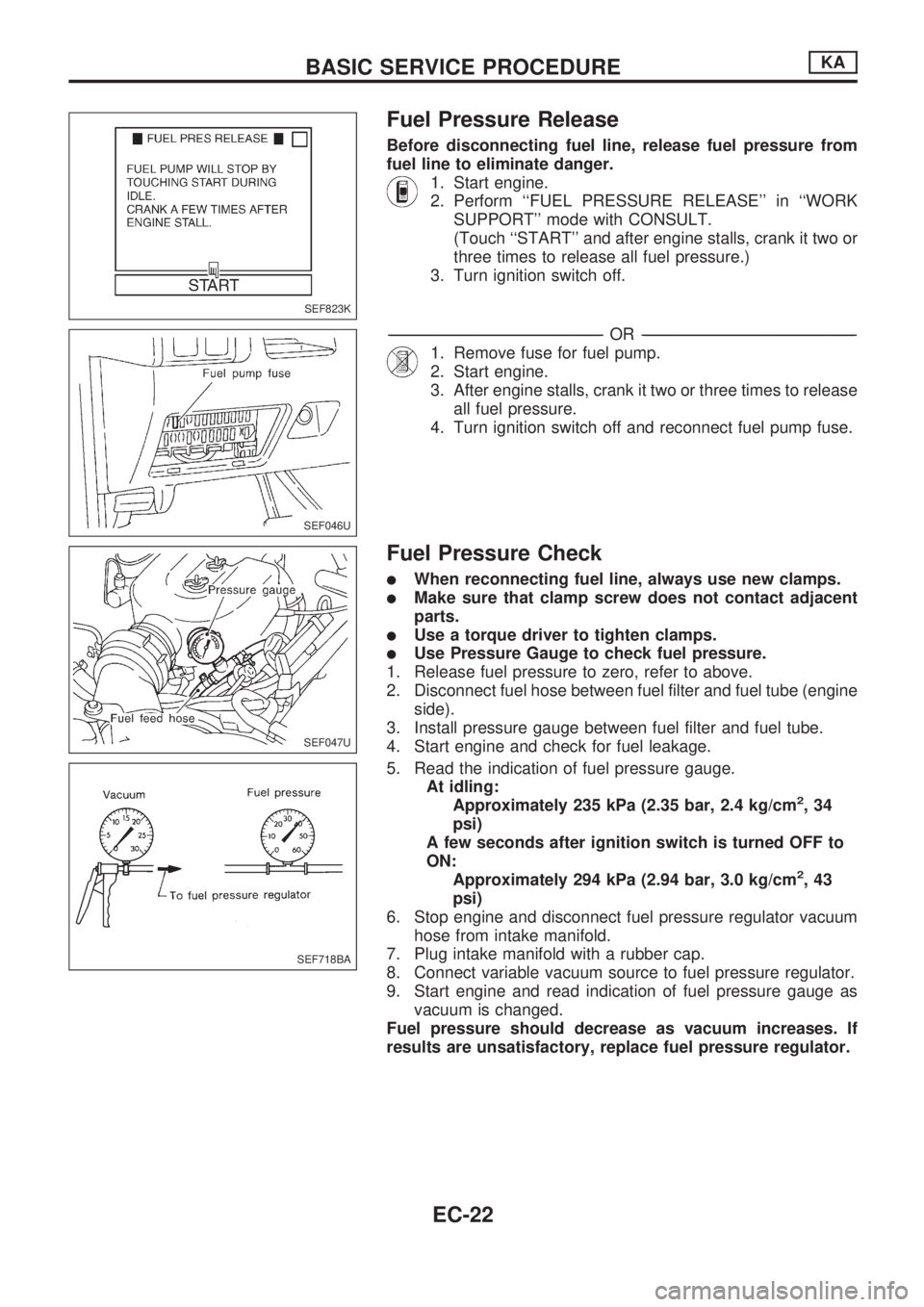
Fuel Pressure Release
Before disconnecting fuel line, release fuel pressure from
fuel line to eliminate danger.
1. Start engine.
2. Perform ``FUEL PRESSURE RELEASE'' in ``WORK
SUPPORT'' mode with CONSULT.
(Touch ``START'' and after engine stalls, crank it two or
three times to release all fuel pressure.)
3. Turn ignition switch off.
-------------------------------------------------------------------------------------------------------------------------------------------------------------------------------------------------------------------------------------------------OR-------------------------------------------------------------------------------------------------------------------------------------------------------------------------------------------------------------------------------------------------
1. Remove fuse for fuel pump.
2. Start engine.
3. After engine stalls, crank it two or three times to release
all fuel pressure.
4. Turn ignition switch off and reconnect fuel pump fuse.
Fuel Pressure Check
lWhen reconnecting fuel line, always use new clamps.
lMake sure that clamp screw does not contact adjacent
parts.
lUse a torque driver to tighten clamps.
lUse Pressure Gauge to check fuel pressure.
1. Release fuel pressure to zero, refer to above.
2. Disconnect fuel hose between fuel filter and fuel tube (engine
side).
3. Install pressure gauge between fuel filter and fuel tube.
4. Start engine and check for fuel leakage.
5. Read the indication of fuel pressure gauge.
At idling:
Approximately 235 kPa (2.35 bar, 2.4 kg/cm
2,34
psi)
A few seconds after ignition switch is turned OFF to
ON:
Approximately 294 kPa (2.94 bar, 3.0 kg/cm
2,43
psi)
6. Stop engine and disconnect fuel pressure regulator vacuum
hose from intake manifold.
7. Plug intake manifold with a rubber cap.
8. Connect variable vacuum source to fuel pressure regulator.
9. Start engine and read indication of fuel pressure gauge as
vacuum is changed.
Fuel pressure should decrease as vacuum increases. If
results are unsatisfactory, replace fuel pressure regulator.
SEF823K
SEF046U
SEF047U
SEF718BA
BASIC SERVICE PROCEDUREKA
EC-22
Page 198 of 1659
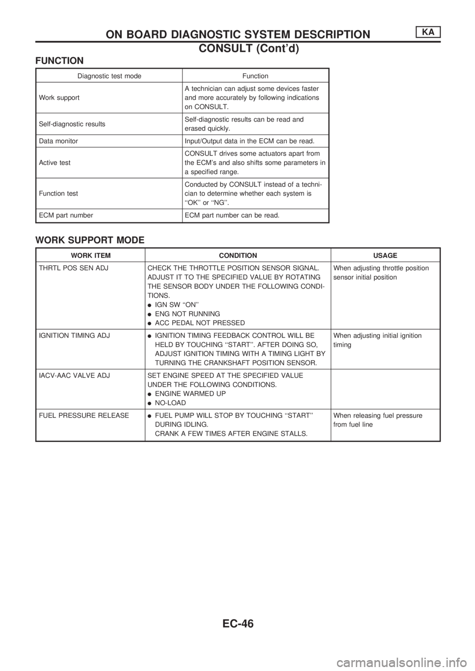
FUNCTION
Diagnostic test mode Function
Work supportA technician can adjust some devices faster
and more accurately by following indications
on CONSULT.
Self-diagnostic resultsSelf-diagnostic results can be read and
erased quickly.
Data monitor Input/Output data in the ECM can be read.
Active testCONSULT drives some actuators apart from
the ECM's and also shifts some parameters in
a specified range.
Function testConducted by CONSULT instead of a techni-
cian to determine whether each system is
``OK'' or ``NG''.
ECM part number ECM part number can be read.
WORK SUPPORT MODE
WORK ITEM CONDITION USAGE
THRTL POS SEN ADJ CHECK THE THROTTLE POSITION SENSOR SIGNAL.
ADJUST IT TO THE SPECIFIED VALUE BY ROTATING
THE SENSOR BODY UNDER THE FOLLOWING CONDI-
TIONS.
lIGN SW ``ON''
lENG NOT RUNNING
lACC PEDAL NOT PRESSEDWhen adjusting throttle position
sensor initial position
IGNITION TIMING ADJ
lIGNITION TIMING FEEDBACK CONTROL WILL BE
HELD BY TOUCHING ``START''. AFTER DOING SO,
ADJUST IGNITION TIMING WITH A TIMING LIGHT BY
TURNING THE CRANKSHAFT POSITION SENSOR.When adjusting initial ignition
timing
IACV-AAC VALVE ADJ SET ENGINE SPEED AT THE SPECIFIED VALUE
UNDER THE FOLLOWING CONDITIONS.
lENGINE WARMED UP
lNO-LOAD
FUEL PRESSURE RELEASE
lFUEL PUMP WILL STOP BY TOUCHING ``START''
DURING IDLING.
CRANK A FEW TIMES AFTER ENGINE STALLS.When releasing fuel pressure
from fuel line
ON BOARD DIAGNOSTIC SYSTEM DESCRIPTIONKA
CONSULT (Cont'd)
EC-46
Page 199 of 1659
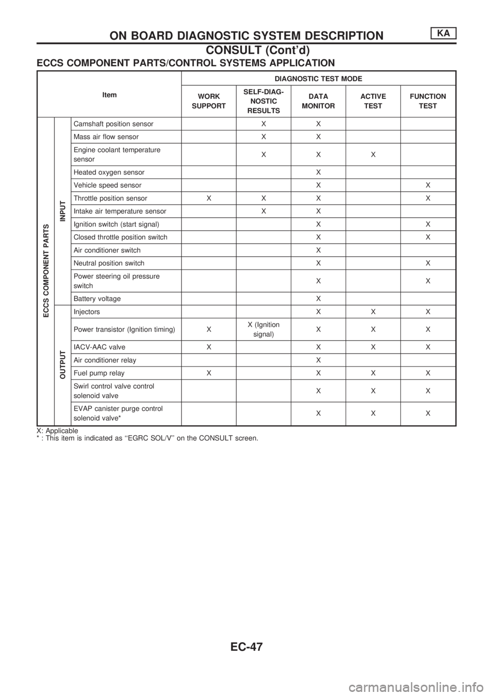
ECCS COMPONENT PARTS/CONTROL SYSTEMS APPLICATION
ItemDIAGNOSTIC TEST MODE
WORK
SUPPORTSELF-DIAG-
NOSTIC
RESULTSDATA
MONITORACTIVE
TESTFUNCTION
TEST
ECCS COMPONENT PARTS
INPUT
Camshaft position sensor X X
Mass air flow sensor X X
Engine coolant temperature
sensorXXX
Heated oxygen sensor X
Vehicle speed sensor X X
Throttle position sensor X X X X
Intake air temperature sensor X X
Ignition switch (start signal) X X
Closed throttle position switch X X
Air conditioner switch X
Neutral position switch X X
Power steering oil pressure
switchXX
Battery voltage X
OUTPUT
Injectors X X X
Power transistor (Ignition timing) XX (Ignition
signal)XXX
IACV-AAC valve X X X X
Air conditioner relay X
Fuel pump relay X X X X
Swirl control valve control
solenoid valveXXX
EVAP canister purge control
solenoid valve*XXX
X: Applicable
* : This item is indicated as ``EGRC SOL/V'' on the CONSULT screen.
ON BOARD DIAGNOSTIC SYSTEM DESCRIPTIONKA
CONSULT (Cont'd)
EC-47
Page 201 of 1659
![NISSAN PICK-UP 1998 Repair Manual Monitored item
[Unit]ECM
input
signalsMain
signalsDescription Remarks
INJ PULSE [msec]
j
lIndicates the actual fuel injection pulse
width compensated by ECM according to
the input signals.lWhen the en NISSAN PICK-UP 1998 Repair Manual Monitored item
[Unit]ECM
input
signalsMain
signalsDescription Remarks
INJ PULSE [msec]
j
lIndicates the actual fuel injection pulse
width compensated by ECM according to
the input signals.lWhen the en](/img/5/57374/w960_57374-200.png)
Monitored item
[Unit]ECM
input
signalsMain
signalsDescription Remarks
INJ PULSE [msec]
j
lIndicates the actual fuel injection pulse
width compensated by ECM according to
the input signals.lWhen the engine is stopped, a certain
computed value is indicated.
IGN TIMING [BTDC]
j
lIndicates the ignition timing computed by
ECM according to the input signals.lWhen the engine is stopped, a certain
value is indicated.
IACV-AAC/V [%]
j
lIndicates the idle air control valve (AAC
valve) control value computed by ECM
according to the input signals.
A/F ALPHA [%]
j
lThe mean value of the air-fuel ratio feed-
back correction factor per cycle is indi-
cated.lWhen the engine is stopped, a certain
value is indicated.
lThis data also includes the data for the
air-fuel ratio learning control.
AIR COND RLY
[ON/OFF]
j
lThe air conditioner relay control condition
(determined by ECM according to the
input signal) is indicated.
FUEL PUMP RLY
[ON/OFF]
j
lIndicates the fuel pump relay control con-
dition determined by ECM according to
the input signals.
SWRL CONT S/V
[ON/OFF]
j
lThe control condition of the swirl control
valve control solenoid valve (determined
by the ECM according to the input signal)
is indicated.
ON ... Swirl control valve is closed
OFF ... Swirl control valve is open
EGRC SOL/V
(EVAP canister purge
control solenoid
valve) [ON/OFF]
j
lThe control condition of the EVAP canis-
ter purge control solenoid valve (deter-
mined by ECM according to the input
signal) is indicated.
ON ... EVAP canister purge control is not
operating
OFF ... EVAP canister purge control is
operational.
VOLTAGE
[V]
lVoltage measured by the voltage probe.
PULSE
[msec] or [Hz] or [%]
lPulse width, frequency or duty cycle
measured by the pulse probe.lOnly ``#'' is displayed if item is unable to
be measured.
lFigures with ``#''s are temporary ones.
They are the same figures as an actual
piece of data which was just previously
measured.
ON BOARD DIAGNOSTIC SYSTEM DESCRIPTIONKA
CONSULT (Cont'd)
EC-49
Page 202 of 1659
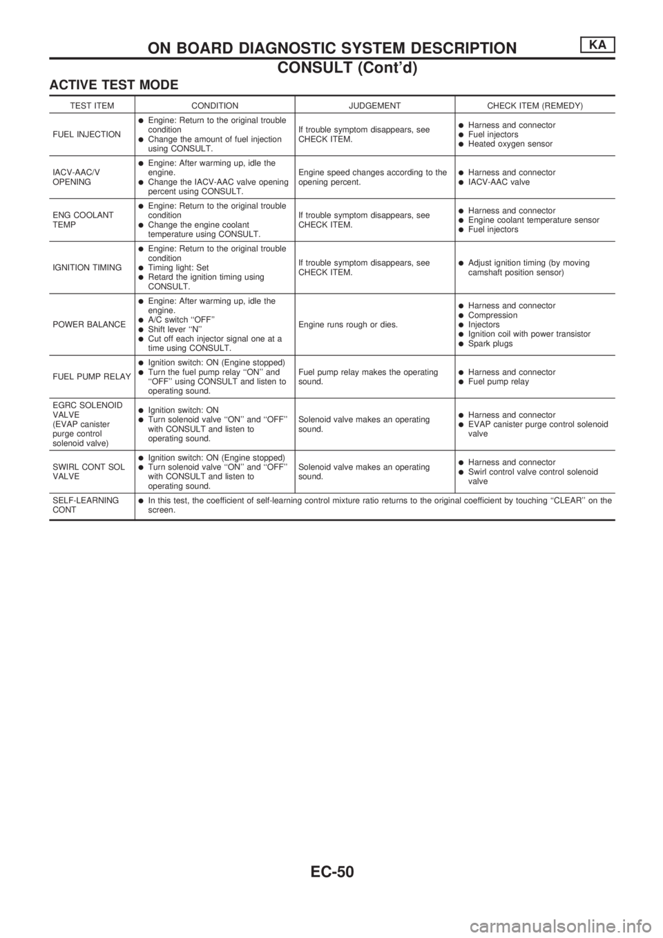
ACTIVE TEST MODE
TEST ITEM CONDITION JUDGEMENT CHECK ITEM (REMEDY)
FUEL INJECTION
lEngine: Return to the original trouble
condition
lChange the amount of fuel injection
using CONSULT.If trouble symptom disappears, see
CHECK ITEM.
lHarness and connectorlFuel injectorslHeated oxygen sensor
IACV-AAC/V
OPENING
lEngine: After warming up, idle the
engine.
lChange the IACV-AAC valve opening
percent using CONSULT.Engine speed changes according to the
opening percent.lHarness and connectorlIACV-AAC valve
ENG COOLANT
TEMP
lEngine: Return to the original trouble
condition
lChange the engine coolant
temperature using CONSULT.If trouble symptom disappears, see
CHECK ITEM.
lHarness and connectorlEngine coolant temperature sensorlFuel injectors
IGNITION TIMING
lEngine: Return to the original trouble
condition
lTiming light: SetlRetard the ignition timing using
CONSULT.If trouble symptom disappears, see
CHECK ITEM.
lAdjust ignition timing (by moving
camshaft position sensor)
POWER BALANCE
lEngine: After warming up, idle the
engine.
lA/C switch ``OFF''lShift lever ``N''lCut off each injector signal one at a
time using CONSULT.Engine runs rough or dies.
lHarness and connectorlCompressionlInjectorslIgnition coil with power transistorlSpark plugs
FUEL PUMP RELAY
lIgnition switch: ON (Engine stopped)lTurn the fuel pump relay ``ON'' and
``OFF'' using CONSULT and listen to
operating sound.Fuel pump relay makes the operating
sound.lHarness and connectorlFuel pump relay
EGRC SOLENOID
VALVE
(EVAP canister
purge control
solenoid valve)
lIgnition switch: ONlTurn solenoid valve ``ON'' and ``OFF''
with CONSULT and listen to
operating sound.Solenoid valve makes an operating
sound.lHarness and connectorlEVAP canister purge control solenoid
valve
SWIRL CONT SOL
VALVE
lIgnition switch: ON (Engine stopped)lTurn solenoid valve ``ON'' and ``OFF''
with CONSULT and listen to
operating sound.Solenoid valve makes an operating
sound.lHarness and connectorlSwirl control valve control solenoid
valve
SELF-LEARNING
CONT
lIn this test, the coefficient of self-learning control mixture ratio returns to the original coefficient by touching ``CLEAR'' on the
screen.
ON BOARD DIAGNOSTIC SYSTEM DESCRIPTIONKA
CONSULT (Cont'd)
EC-50
Page 203 of 1659
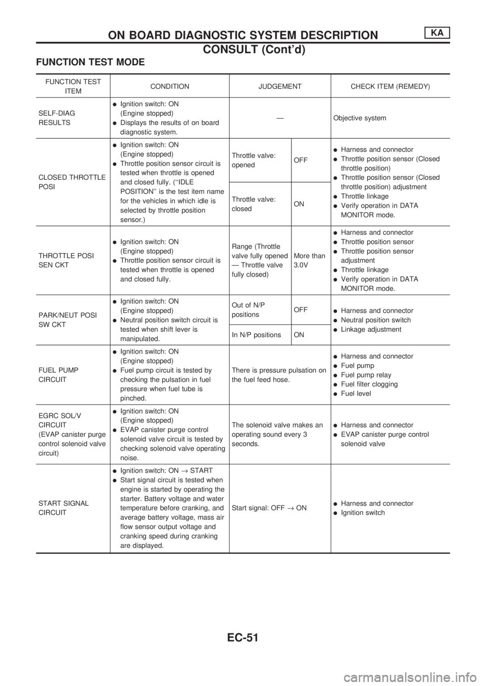
FUNCTION TEST MODE
FUNCTION TEST
ITEMCONDITION JUDGEMENT CHECK ITEM (REMEDY)
SELF-DIAG
RESULTS
lIgnition switch: ON
(Engine stopped)
lDisplays the results of on board
diagnostic system.Ð Objective system
CLOSED THROTTLE
POSI
lIgnition switch: ON
(Engine stopped)
lThrottle position sensor circuit is
tested when throttle is opened
and closed fully. (``IDLE
POSITION'' is the test item name
for the vehicles in which idle is
selected by throttle position
sensor.)Throttle valve:
openedOFF
lHarness and connector
lThrottle position sensor (Closed
throttle position)
lThrottle position sensor (Closed
throttle position) adjustment
lThrottle linkage
lVerify operation in DATA
MONITOR mode. Throttle valve:
closedON
THROTTLE POSI
SEN CKT
lIgnition switch: ON
(Engine stopped)
lThrottle position sensor circuit is
tested when throttle is opened
and closed fully.Range (Throttle
valve fully opened
Ð Throttle valve
fully closed)More than
3.0V
lHarness and connector
lThrottle position sensor
lThrottle position sensor
adjustment
lThrottle linkage
lVerify operation in DATA
MONITOR mode.
PARK/NEUT POSI
SW CKT
lIgnition switch: ON
(Engine stopped)
lNeutral position switch circuit is
tested when shift lever is
manipulated.Out of N/P
positionsOFF
lHarness and connector
lNeutral position switch
lLinkage adjustment
In N/P positions ON
FUEL PUMP
CIRCUIT
lIgnition switch: ON
(Engine stopped)
lFuel pump circuit is tested by
checking the pulsation in fuel
pressure when fuel tube is
pinched.There is pressure pulsation on
the fuel feed hose.
lHarness and connector
lFuel pump
lFuel pump relay
lFuel filter clogging
lFuel level
EGRC SOL/V
CIRCUIT
(EVAP canister purge
control solenoid valve
circuit)
lIgnition switch: ON
(Engine stopped)
lEVAP canister purge control
solenoid valve circuit is tested by
checking solenoid valve operating
noise.The solenoid valve makes an
operating sound every 3
seconds.lHarness and connector
lEVAP canister purge control
solenoid valve
START SIGNAL
CIRCUIT
lIgnition switch: ON®START
lStart signal circuit is tested when
engine is started by operating the
starter. Battery voltage and water
temperature before cranking, and
average battery voltage, mass air
flow sensor output voltage and
cranking speed during cranking
are displayed.Start signal: OFF®ON
lHarness and connector
lIgnition switch
ON BOARD DIAGNOSTIC SYSTEM DESCRIPTIONKA
CONSULT (Cont'd)
EC-51
Page 204 of 1659
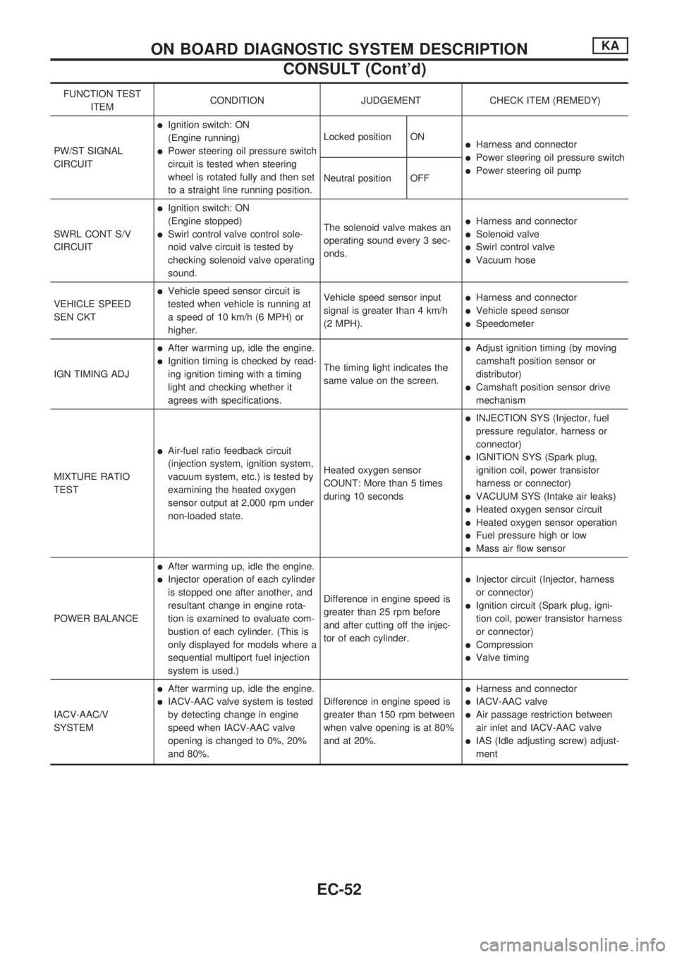
FUNCTION TEST
ITEMCONDITION JUDGEMENT CHECK ITEM (REMEDY)
PW/ST SIGNAL
CIRCUIT
lIgnition switch: ON
(Engine running)
lPower steering oil pressure switch
circuit is tested when steering
wheel is rotated fully and then set
to a straight line running position.Locked position ONlHarness and connector
lPower steering oil pressure switch
lPower steering oil pump
Neutral position OFF
SWRL CONT S/V
CIRCUIT
lIgnition switch: ON
(Engine stopped)
lSwirl control valve control sole-
noid valve circuit is tested by
checking solenoid valve operating
sound.The solenoid valve makes an
operating sound every 3 sec-
onds.
lHarness and connector
lSolenoid valve
lSwirl control valve
lVacuum hose
VEHICLE SPEED
SEN CKT
lVehicle speed sensor circuit is
tested when vehicle is running at
a speed of 10 km/h (6 MPH) or
higher.Vehicle speed sensor input
signal is greater than 4 km/h
(2 MPH).lHarness and connector
lVehicle speed sensor
lSpeedometer
IGN TIMING ADJ
lAfter warming up, idle the engine.
lIgnition timing is checked by read-
ing ignition timing with a timing
light and checking whether it
agrees with specifications.The timing light indicates the
same value on the screen.
lAdjust ignition timing (by moving
camshaft position sensor or
distributor)
lCamshaft position sensor drive
mechanism
MIXTURE RATIO
TEST
lAir-fuel ratio feedback circuit
(injection system, ignition system,
vacuum system, etc.) is tested by
examining the heated oxygen
sensor output at 2,000 rpm under
non-loaded state.Heated oxygen sensor
COUNT: More than 5 times
during 10 seconds
lINJECTION SYS (Injector, fuel
pressure regulator, harness or
connector)
lIGNITION SYS (Spark plug,
ignition coil, power transistor
harness or connector)
lVACUUM SYS (Intake air leaks)
lHeated oxygen sensor circuit
lHeated oxygen sensor operation
lFuel pressure high or low
lMass air flow sensor
POWER BALANCE
lAfter warming up, idle the engine.
lInjector operation of each cylinder
is stopped one after another, and
resultant change in engine rota-
tion is examined to evaluate com-
bustion of each cylinder. (This is
only displayed for models where a
sequential multiport fuel injection
system is used.)Difference in engine speed is
greater than 25 rpm before
and after cutting off the injec-
tor of each cylinder.lInjector circuit (Injector, harness
or connector)
lIgnition circuit (Spark plug, igni-
tion coil, power transistor harness
or connector)
lCompression
lValve timing
IACV-AAC/V
SYSTEM
lAfter warming up, idle the engine.
lIACV-AAC valve system is tested
by detecting change in engine
speed when IACV-AAC valve
opening is changed to 0%, 20%
and 80%.Difference in engine speed is
greater than 150 rpm between
when valve opening is at 80%
and at 20%.
lHarness and connector
lIACV-AAC valve
lAir passage restriction between
air inlet and IACV-AAC valve
lIAS (Idle adjusting screw) adjust-
ment
ON BOARD DIAGNOSTIC SYSTEM DESCRIPTIONKA
CONSULT (Cont'd)
EC-52
Page 213 of 1659
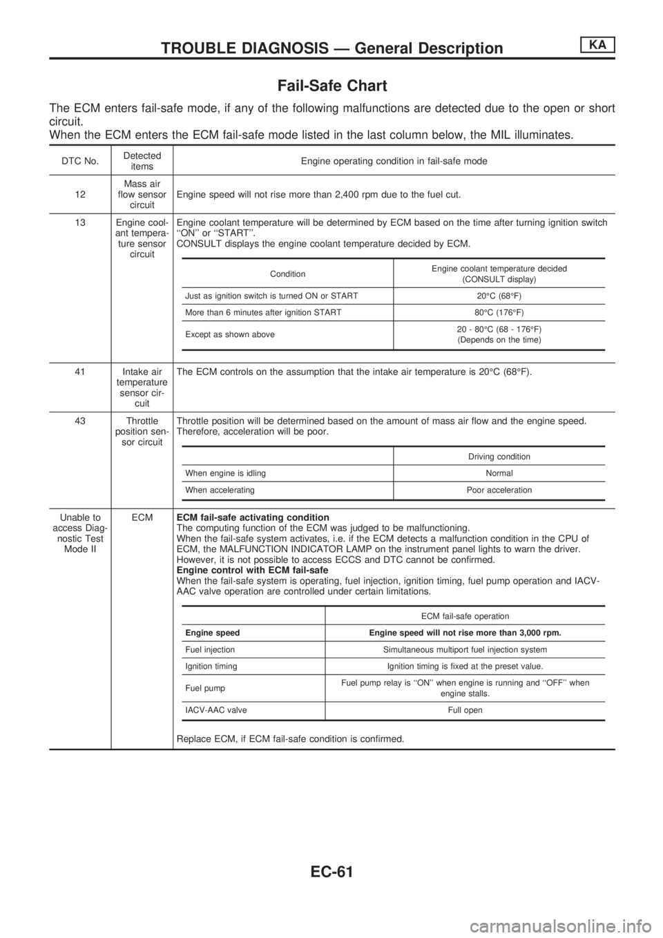
Fail-Safe Chart
The ECM enters fail-safe mode, if any of the following malfunctions are detected due to the open or short
circuit.
When the ECM enters the ECM fail-safe mode listed in the last column below, the MIL illuminates.
DTC No.Detected
itemsEngine operating condition in fail-safe mode
12Mass air
flow sensor
circuitEngine speed will not rise more than 2,400 rpm due to the fuel cut.
13 Engine cool-
ant tempera-
ture sensor
circuitEngine coolant temperature will be determined by ECM based on the time after turning ignition switch
``ON'' or ``START''.
CONSULT displays the engine coolant temperature decided by ECM.
41 Intake air
temperature
sensor cir-
cuitThe ECM controls on the assumption that the intake air temperature is 20ÉC (68ÉF).
43 Throttle
position sen-
sor circuitThrottle position will be determined based on the amount of mass air flow and the engine speed.
Therefore, acceleration will be poor.
Unable to
access Diag-
nostic Test
Mode IIECMECM fail-safe activating condition
The computing function of the ECM was judged to be malfunctioning.
When the fail-safe system activates, i.e. if the ECM detects a malfunction condition in the CPU of
ECM, the MALFUNCTION INDICATOR LAMP on the instrument panel lights to warn the driver.
However, it is not possible to access ECCS and DTC cannot be confirmed.
Engine control with ECM fail-safe
When the fail-safe system is operating, fuel injection, ignition timing, fuel pump operation and IACV-
AAC valve operation are controlled under certain limitations.
Replace ECM, if ECM fail-safe condition is confirmed.
ConditionEngine coolant temperature decided
(CONSULT display)
Just as ignition switch is turned ON or START 20ÉC (68ÉF)
More than 6 minutes after ignition START 80ÉC (176ÉF)
Except as shown above20 - 80ÉC (68 - 176ÉF)
(Depends on the time)
Driving condition
When engine is idling Normal
When accelerating Poor acceleration
ECM fail-safe operation
Engine speed Engine speed will not rise more than 3,000 rpm.
Fuel injection Simultaneous multiport fuel injection system
Ignition timing Ignition timing is fixed at the preset value.
Fuel pumpFuel pump relay is ``ON'' when engine is running and ``OFF'' when
engine stalls.
IACV-AAC valve Full open
TROUBLE DIAGNOSIS Ð General DescriptionKA
EC-61