key NISSAN PICK-UP 1998 Repair Manual
[x] Cancel search | Manufacturer: NISSAN, Model Year: 1998, Model line: PICK-UP, Model: NISSAN PICK-UP 1998Pages: 1659, PDF Size: 53.39 MB
Page 64 of 1659
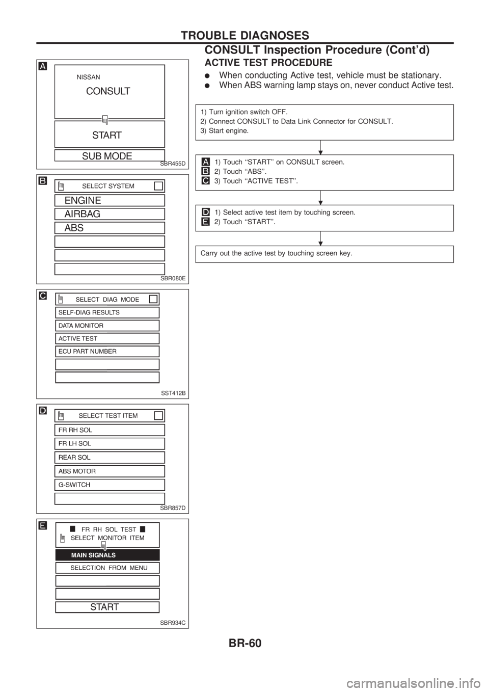
ACTIVE TEST PROCEDURE
lWhen conducting Active test, vehicle must be stationary.
lWhen ABS warning lamp stays on, never conduct Active test.
1) Turn ignition switch OFF.
2) Connect CONSULT to Data Link Connector for CONSULT.
3) Start engine.
1) Touch ``START'' on CONSULT screen.
2) Touch ``ABS''.
3) Touch ``ACTIVE TEST''.
1) Select active test item by touching screen.
2) Touch ``START''.
Carry out the active test by touching screen key.
SBR455D
SBR080E
SST412B
SBR857D
SBR934C
.
.
.
TROUBLE DIAGNOSES
CONSULT Inspection Procedure (Cont'd)
BR-60
Page 195 of 1659
DIAGNOSTIC TEST MODE IÐBULB CHECK
In this mode, the MALFUNCTION INDICATOR LAMP on the instrument panel should stay ON. If it remains
OFF, check the bulb. (See the WARNING LAMPS AND CHIME in the EL section. Or see EC-173, 174.)
DIAGNOSTIC TEST MODE IÐMALFUNCTION WARNING
MALFUNCTION
INDICATOR LAMPCondition
ON When the malfunction is detected (Refer to EC-1.) or the ECM's CPU is malfunctioning.
OFF No malfunction
lThese Diagnostic Trouble Code Numbers are clarified in Diagnostic Test Mode II (SELF-DIAGNOSTIC
RESULTS).
DIAGNOSTIC TEST MODE IIÐSELF-DIAGNOSTIC RESULTS
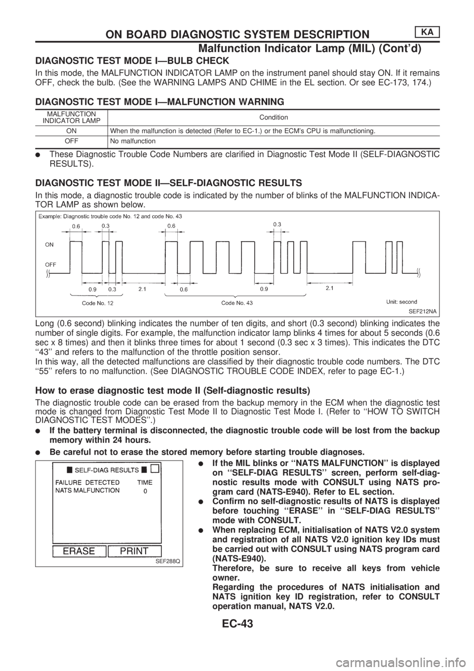
In this mode, a diagnostic trouble code is indicated by the number of blinks of the MALFUNCTION INDICA-
TOR LAMP as shown below.
Long (0.6 second) blinking indicates the number of ten digits, and short (0.3 second) blinking indicates the
number of single digits. For example, the malfunction indicator lamp blinks 4 times for about 5 seconds (0.6
sec x 8 times) and then it blinks three times for about 1 second (0.3 sec x 3 times). This indicates the DTC
``43'' and refers to the malfunction of the throttle position sensor.
In this way, all the detected malfunctions are classified by their diagnostic trouble code numbers. The DTC
``55'' refers to no malfunction. (See DIAGNOSTIC TROUBLE CODE INDEX, refer to page EC-1.)
How to erase diagnostic test mode II (Self-diagnostic results)
The diagnostic trouble code can be erased from the backup memory in the ECM when the diagnostic test
mode is changed from Diagnostic Test Mode II to Diagnostic Test Mode I. (Refer to ``HOW TO SWITCH
DIAGNOSTIC TEST MODES''.)
lIf the battery terminal is disconnected, the diagnostic trouble code will be lost from the backup
memory within 24 hours.
lBe careful not to erase the stored memory before starting trouble diagnoses.
lIf the MIL blinks or ``NATS MALFUNCTION'' is displayed
on ``SELF-DIAG RESULTS'' screen, perform self-diag-
nostic results mode with CONSULT using NATS pro-
gram card (NATS-E940). Refer to EL section.
lConfirm no self-diagnostic results of NATS is displayed
before touching ``ERASE'' in ``SELF-DIAG RESULTS''
mode with CONSULT.
lWhen replacing ECM, initialisation of NATS V2.0 system
and registration of all NATS V2.0 ignition key IDs must
be carried out with CONSULT using NATS program card
(NATS-E940).
Therefore, be sure to receive all keys from vehicle
owner.
Regarding the procedures of NATS initialisation and
NATS ignition key ID registration, refer to CONSULT
operation manual, NATS V2.0.
SEF212NA
SEF288Q
ON BOARD DIAGNOSTIC SYSTEM DESCRIPTIONKA
Malfunction Indicator Lamp (MIL) (Cont'd)
EC-43
Page 333 of 1659
2. Install injection pump.
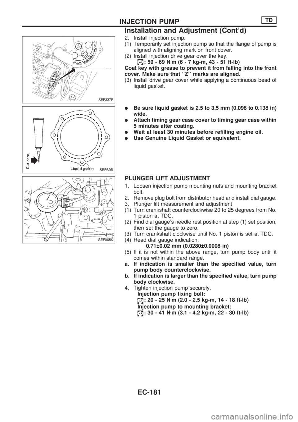
(1) Temporarily set injection pump so that the flange of pump is
aligned with aligning mark on front cover.
(2) Install injection drive gear over the key.
:59-69Nzm (6 - 7 kg-m, 43 - 51 ft-lb)
Coat key with grease to prevent it from falling into the front
cover. Make sure that ``Z'' marks are aligned.
(3) Install drive gear cover while applying a continuous bead of
liquid gasket.
lBe sure liquid gasket is 2.5 to 3.5 mm (0.098 to 0.138 in)
wide.
lAttach timing gear case cover to timing gear case within
5 minutes after coating.
lWait at least 30 minutes before refilling engine oil.
lUse Genuine Liquid Gasket or equivalent.
PLUNGER LIFT ADJUSTMENT
1. Loosen injection pump mounting nuts and mounting bracket
bolt.
2. Remove plug bolt from distributor head and install dial gauge.
3. Plunger lift measurement and adjustment
(1) Turn crankshaft counterclockwise 20 to 25 degrees from No.
1 piston at TDC.
(2) Find dial gauge's needle rest position at step (1) set position,
then set the gauge to zero.
(3) Turn crankshaft clockwise until No. 1 piston is set at TDC.
(4) Read dial gauge indication.
0.71 0.02 mm (0.0280 0.0008 in)
(5) If it is not within the above range, turn pump body until it
comes within standard range.
a. If indication is smaller than the specified value, turn
pump body counterclockwise.
b. If indication is larger than the specified value, turn pump
body clockwise.
4. Tighten injection pump securely.
Injection pump fixing bolt:
:20-25Nzm (2.0 - 2.5 kg-m, 14 - 18 ft-lb)
Injection pump to mounting bracket:
:30-41Nzm (3.1 - 4.2 kg-m, 22 - 30 ft-lb)
SEF337F
SEF626I
SEF065K
INJECTION PUMPTD
Installation and Adjustment (Cont'd)
EC-181
Page 344 of 1659
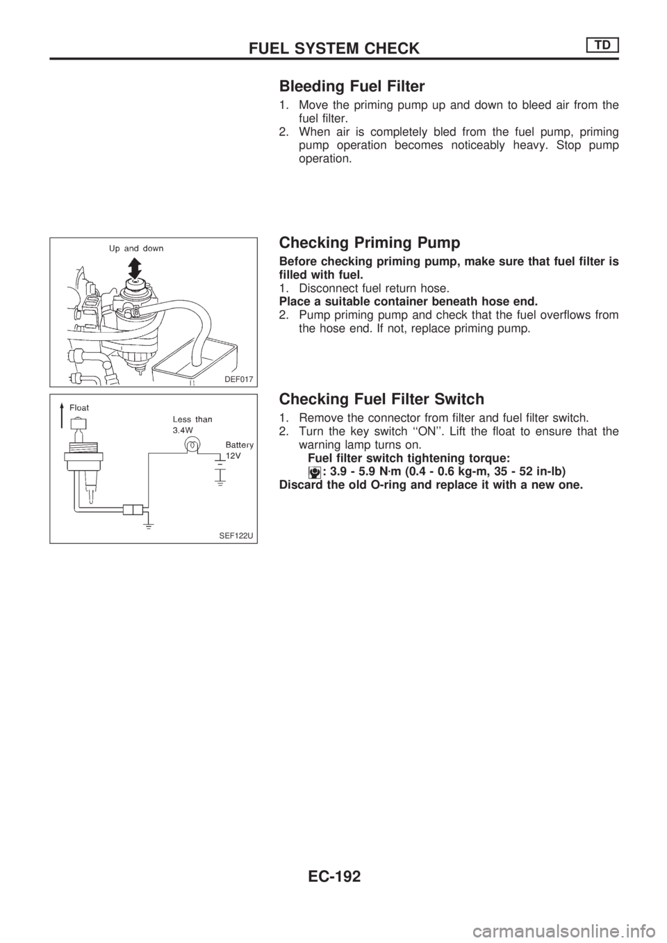
Bleeding Fuel Filter
1. Move the priming pump up and down to bleed air from the
fuel filter.
2. When air is completely bled from the fuel pump, priming
pump operation becomes noticeably heavy. Stop pump
operation.
Checking Priming Pump
Before checking priming pump, make sure that fuel filter is
filled with fuel.
1. Disconnect fuel return hose.
Place a suitable container beneath hose end.
2. Pump priming pump and check that the fuel overflows from
the hose end. If not, replace priming pump.
Checking Fuel Filter Switch
1. Remove the connector from filter and fuel filter switch.
2. Turn the key switch ``ON''. Lift the float to ensure that the
warning lamp turns on.
Fuel filter switch tightening torque:
: 3.9 - 5.9 Nzm (0.4 - 0.6 kg-m, 35 - 52 in-lb)
Discard the old O-ring and replace it with a new one.
DEF017
SEF122U
FUEL SYSTEM CHECKTD
EC-192
Page 556 of 1659
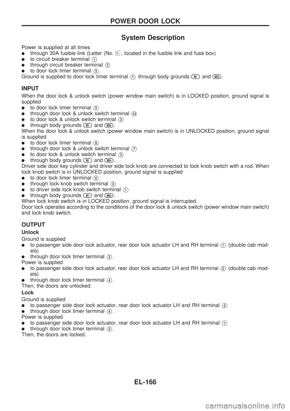
System Description
Power is supplied at all times
lthrough 30A fusible link (Letter (No.b, located in the fusible link and fuse box)
lto circuit breaker terminalV1
lthrough circuit breaker terminalV2
lto door lock timer terminalV3.
Ground is supplied to door lock timer terminal
V1through body groundsM1andM54.
INPUT
When the door lock & unlock switch (power window main switch) is in LOCKED position, ground signal is
supplied
lto door lock timer terminalV5
lthrough door lock & unlock switch terminalV14
lto door lock & unlock switch terminalV3
lthrough body groundsM1andM54.
When the door lock & unlock switch (power window main switch) is in UNLOCKED position, ground signal
is supplied
lto door lock timer terminalV8
lthrough door lock & unlock switch terminalV7
lto door lock & unlock switch terminalV3
lthrough body groundsM1andM54.
Driver side door key cylinder and driver side lock knob are connected to lock knob switch with a rod. When
lock knob switch is in UNLOCKED position, ground signal is supplied
lto door lock timer terminalV6
lthrough lock knob switch terminalV2
lto driver side lock knob switch terminalV1
lthrough body groundsM1andM54.
When lock knob switch is in LOCKED position, ground signal is interrupted.
Door lock operates according to the conditions of the door lock & unlock switch (power window main switch)
and lock knob switch.
OUTPUT
Unlock
Ground is supplied
lto passenger side door lock actuator, rear door lock actuator LH and RH terminalV1(double cab mod-
els)
lthrough door lock timer terminalV2.
Power is supplied
lto passenger side door lock actuator, rear door lock actuator LH and RH terminalV2(double cab mod-
els)
lthrough door lock timer terminalV4.
Then, the doors are unlocked.
Lock
Ground is supplied
lto passenger side door lock actuator, rear door lock actuator LH and RH terminalV2
lthrough door lock timer terminalV4.
Power is supplied
lto passenger side door lock actuator, rear door lock actuator LH and RH terminalV1
lthrough door lock timer terminalV2.
Then, the doors are locked.
POWER DOOR LOCK
EL-166
Page 563 of 1659
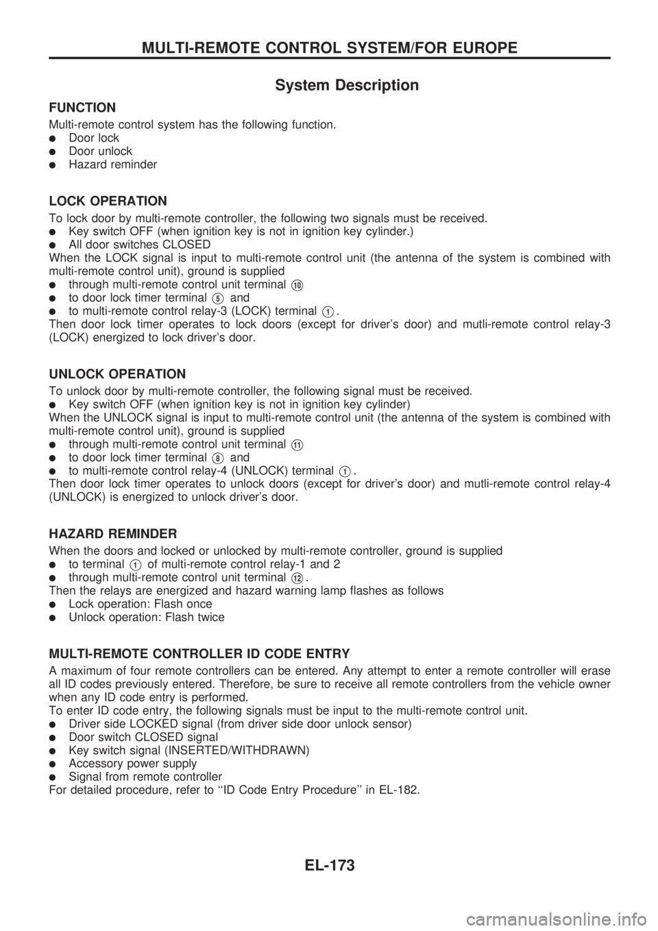
System Description
FUNCTION
Multi-remote control system has the following function.
lDoor lock
lDoor unlock
lHazard reminder
LOCK OPERATION
To lock door by multi-remote controller, the following two signals must be received.
lKey switch OFF (when ignition key is not in ignition key cylinder.)
lAll door switches CLOSED
When the LOCK signal is input to multi-remote control unit (the antenna of the system is combined with
multi-remote control unit), ground is supplied
lthrough multi-remote control unit terminalV10
lto door lock timer terminalV5and
lto multi-remote control relay-3 (LOCK) terminalV1.
Then door lock timer operates to lock doors (except for driver's door) and mutli-remote control relay-3
(LOCK) energized to lock driver's door.
UNLOCK OPERATION
To unlock door by multi-remote controller, the following signal must be received.
lKey switch OFF (when ignition key is not in ignition key cylinder)
When the UNLOCK signal is input to multi-remote control unit (the antenna of the system is combined with
multi-remote control unit), ground is supplied
lthrough multi-remote control unit terminalV11
lto door lock timer terminalV8and
lto multi-remote control relay-4 (UNLOCK) terminalV1.
Then door lock timer operates to unlock doors (except for driver's door) and mutli-remote control relay-4
(UNLOCK) is energized to unlock driver's door.
HAZARD REMINDER
When the doors and locked or unlocked by multi-remote controller, ground is supplied
lto terminalV1of multi-remote control relay-1 and 2
lthrough multi-remote control unit terminalV12.
Then the relays are energized and hazard warning lamp flashes as follows
lLock operation: Flash once
lUnlock operation: Flash twice
MULTI-REMOTE CONTROLLER ID CODE ENTRY
A maximum of four remote controllers can be entered. Any attempt to enter a remote controller will erase
all ID codes previously entered. Therefore, be sure to receive all remote controllers from the vehicle owner
when any ID code entry is performed.
To enter ID code entry, the following signals must be input to the multi-remote control unit.
lDriver side LOCKED signal (from driver side door unlock sensor)
lDoor switch CLOSED signal
lKey switch signal (INSERTED/WITHDRAWN)
lAccessory power supply
lSignal from remote controller
For detailed procedure, refer to ``ID Code Entry Procedure'' in EL-182.
MULTI-REMOTE CONTROL SYSTEM/FOR EUROPE
EL-173
Page 569 of 1659
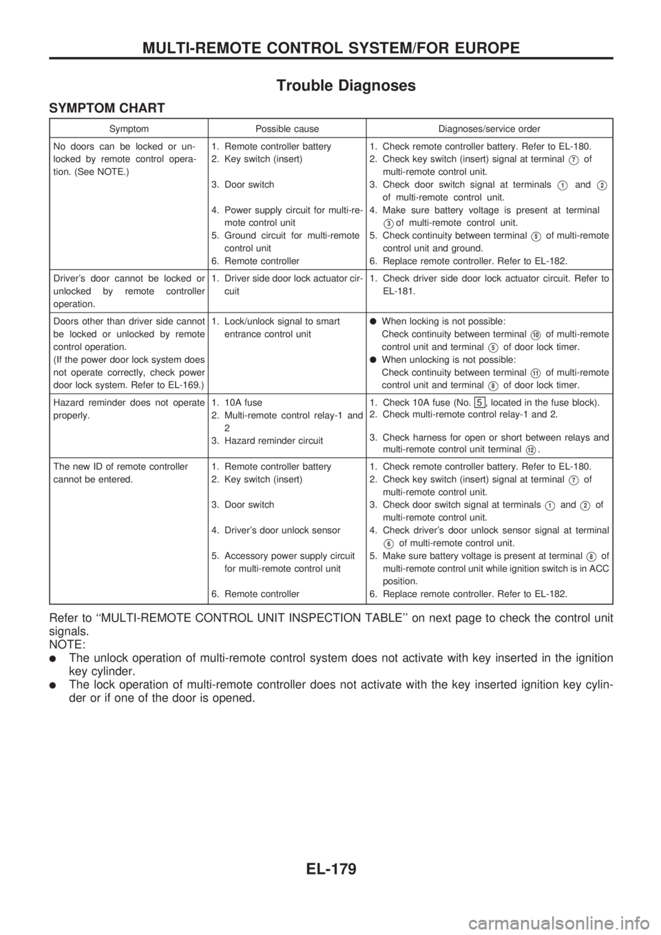
Trouble Diagnoses
SYMPTOM CHART
Symptom Possible cause Diagnoses/service order
No doors can be locked or un-
locked by remote control opera-
tion. (See NOTE.)1. Remote controller battery
2. Key switch (insert)
3. Door switch
4. Power supply circuit for multi-re-
mote control unit
5. Ground circuit for multi-remote
control unit
6. Remote controller1. Check remote controller battery. Refer to EL-180.
2. Check key switch (insert) signal at terminal
V7of
multi-remote control unit.
3. Check door switch signal at terminals
V1andV2
of multi-remote control unit.
4. Make sure battery voltage is present at terminal
V3of multi-remote control unit.
5. Check continuity between terminal
V5of multi-remote
control unit and ground.
6. Replace remote controller. Refer to EL-182.
Driver's door cannot be locked or
unlocked by remote controller
operation.1. Driver side door lock actuator cir-
cuit1. Check driver side door lock actuator circuit. Refer to
EL-181.
Doors other than driver side cannot
be locked or unlocked by remote
control operation.
(If the power door lock system does
not operate correctly, check power
door lock system. Refer to EL-169.)1. Lock/unlock signal to smart
entrance control unit
lWhen locking is not possible:
Check continuity between terminal
V10of multi-remote
control unit and terminal
V5of door lock timer.
lWhen unlocking is not possible:
Check continuity between terminal
V11of multi-remote
control unit and terminal
V8of door lock timer.
Hazard reminder does not operate
properly.1. 10A fuse
2. Multi-remote control relay-1 and
2
3. Hazard reminder circuit1. Check 10A fuse (No.
5 , located in the fuse block).
2. Check multi-remote control relay-1 and 2.
3. Check harness for open or short between relays and
multi-remote control unit terminal
V12.
The new ID of remote controller
cannot be entered.1. Remote controller battery
2. Key switch (insert)
3. Door switch
4. Driver's door unlock sensor
5. Accessory power supply circuit
for multi-remote control unit
6. Remote controller1. Check remote controller battery. Refer to EL-180.
2. Check key switch (insert) signal at terminal
V7of
multi-remote control unit.
3. Check door switch signal at terminals
V1andV2of
multi-remote control unit.
4. Check driver's door unlock sensor signal at terminal
V6of multi-remote control unit.
5. Make sure battery voltage is present at terminal
V8of
multi-remote control unit while ignition switch is in ACC
position.
6. Replace remote controller. Refer to EL-182.
Refer to ``MULTI-REMOTE CONTROL UNIT INSPECTION TABLE'' on next page to check the control unit
signals.
NOTE:
lThe unlock operation of multi-remote control system does not activate with key inserted in the ignition
key cylinder.
lThe lock operation of multi-remote controller does not activate with the key inserted ignition key cylin-
der or if one of the door is opened.
MULTI-REMOTE CONTROL SYSTEM/FOR EUROPE
EL-179
Page 570 of 1659
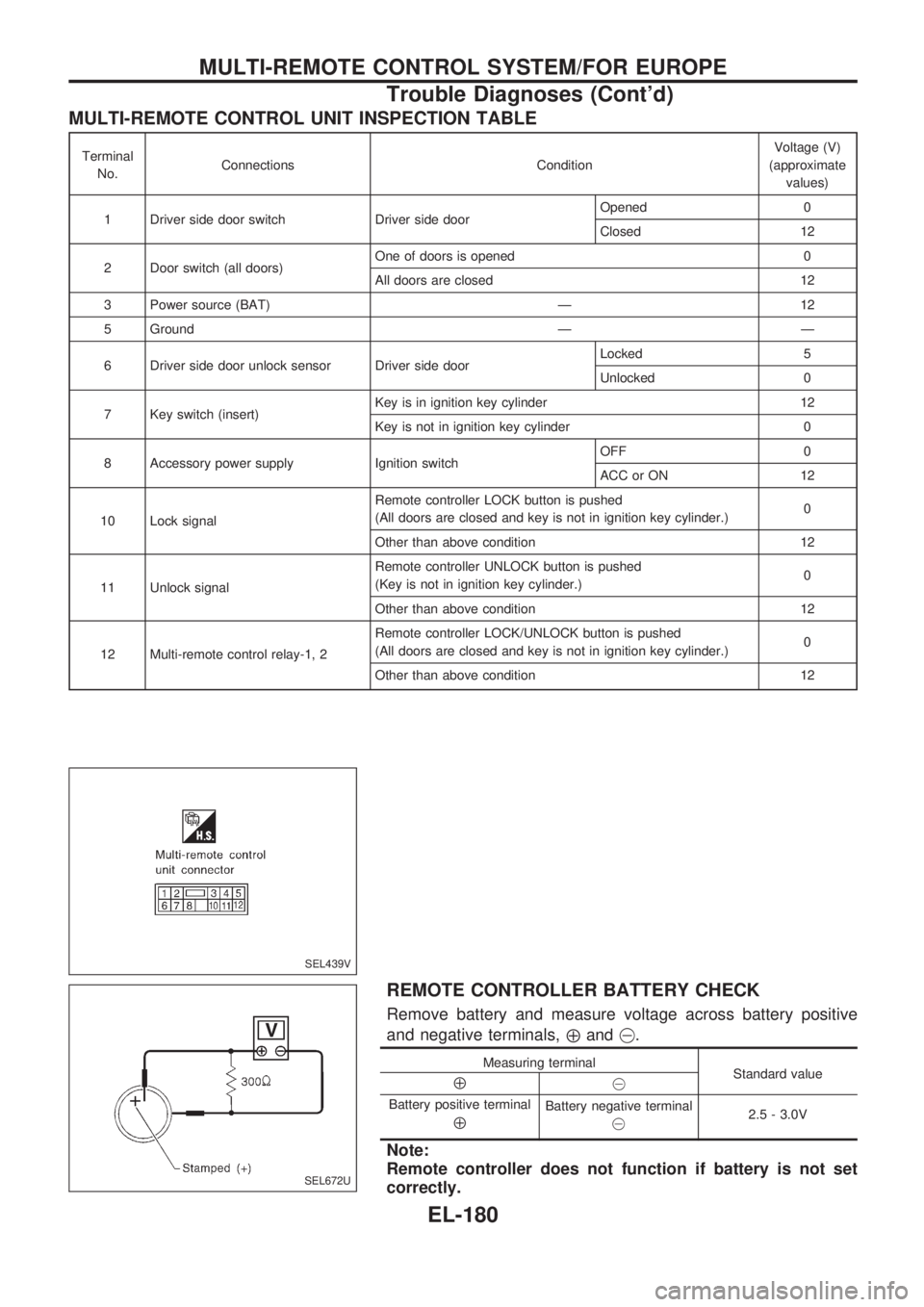
MULTI-REMOTE CONTROL UNIT INSPECTION TABLE
Terminal
No.Connections ConditionVoltage (V)
(approximate
values)
1 Driver side door switch Driver side doorOpened 0
Closed 12
2 Door switch (all doors)One of doors is opened 0
All doors are closed 12
3 Power source (BAT) Ð 12
5 Ground Ð Ð
6 Driver side door unlock sensor Driver side doorLocked 5
Unlocked 0
7 Key switch (insert)Key is in ignition key cylinder 12
Key is not in ignition key cylinder 0
8 Accessory power supply Ignition switchOFF 0
ACC or ON 12
10 Lock signalRemote controller LOCK button is pushed
(All doors are closed and key is not in ignition key cylinder.)0
Other than above condition 12
11 Unlock signalRemote controller UNLOCK button is pushed
(Key is not in ignition key cylinder.)0
Other than above condition 12
12 Multi-remote control relay-1, 2Remote controller LOCK/UNLOCK button is pushed
(All doors are closed and key is not in ignition key cylinder.)0
Other than above condition 12
REMOTE CONTROLLER BATTERY CHECK
Remove battery and measure voltage across battery positive
and negative terminals,
Åand@.
Measuring terminal
Standard value
Å@
Battery positive terminal
Å
Battery negative terminal
@2.5 - 3.0V
Note:
Remote controller does not function if battery is not set
correctly.
SEL439V
SEL672U
MULTI-REMOTE CONTROL SYSTEM/FOR EUROPE
Trouble Diagnoses (Cont'd)
EL-180
Page 572 of 1659
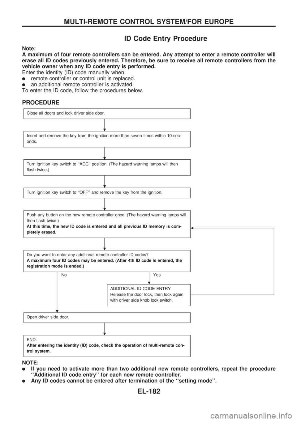
ID Code Entry Procedure
Note:
A maximum of four remote controllers can be entered. Any attempt to enter a remote controller will
erase all ID codes previously entered. Therefore, be sure to receive all remote controllers from the
vehicle owner when any ID code entry is performed.
Enter the identity (ID) code manually when:
lremote controller or control unit is replaced.
lan additional remote controller is activated.
To enter the ID code, follow the procedures below.
PROCEDURE
Close all doors and lock driver side door.
Insert and remove the key from the ignition more than seven times within 10 sec-
onds.
Turn ignition key switch to ``ACC'' position. (The hazard warning lamps will then
flash twice.)
Turn ignition key switch to ``OFF'' and remove the key from the ignition.
Push any button on the new remote controller once. (The hazard warning lamps will
then flash twice.)
At this time, the new ID code is entered and all previous ID memory is com-
pletely erased.
b
Do you want to enter any additional remote controller ID codes?
A maximum four ID codes may be entered. (After 4th ID code is entered, the
registration mode is ended.)
No Yes
ADDITIONAL ID CODE ENTRY
Release the door lock, then lock again
with driver side knob lock switch.
Open driver side door.
END.
After entering the identity (ID) code, check the operation of multi-remote con-
trol system.
NOTE:
lIf you need to activate more than two additional new remote controllers, repeat the procedure
``Additional ID code entry'' for each new remote controller.
lAny ID codes cannot be entered after termination of the ``setting mode''.
.
.
.
.
.
.
.
.
MULTI-REMOTE CONTROL SYSTEM/FOR EUROPE
EL-182
Page 573 of 1659
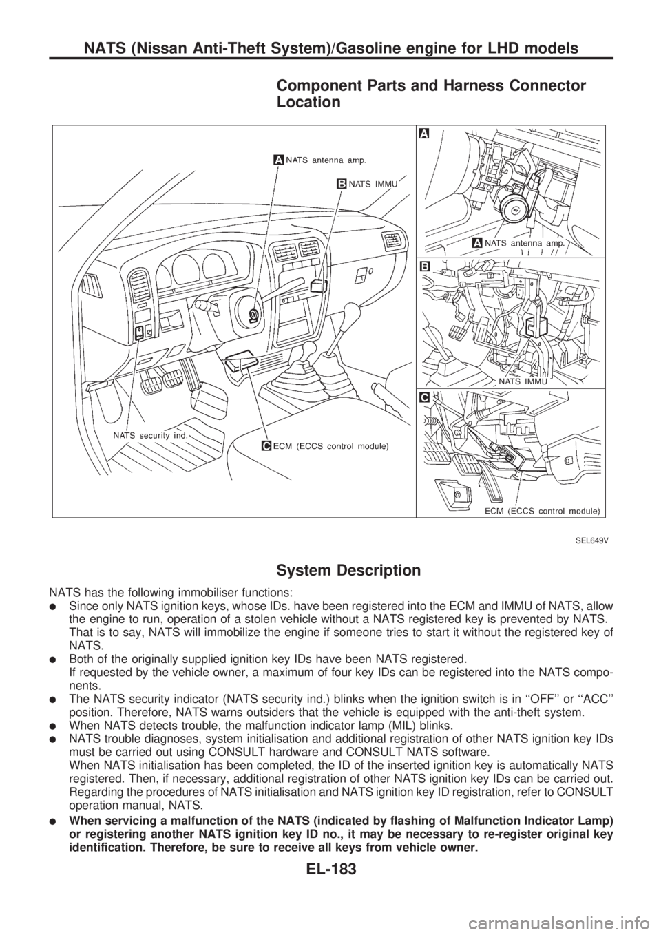
Component Parts and Harness Connector
Location
System Description
NATS has the following immobiliser functions:
lSince only NATS ignition keys, whose IDs. have been registered into the ECM and IMMU of NATS, allow
the engine to run, operation of a stolen vehicle without a NATS registered key is prevented by NATS.
That is to say, NATS will immobilize the engine if someone tries to start it without the registered key of
NATS.
lBoth of the originally supplied ignition key IDs have been NATS registered.
If requested by the vehicle owner, a maximum of four key IDs can be registered into the NATS compo-
nents.
lThe NATS security indicator (NATS security ind.) blinks when the ignition switch is in ``OFF'' or ``ACC''
position. Therefore, NATS warns outsiders that the vehicle is equipped with the anti-theft system.
lWhen NATS detects trouble, the malfunction indicator lamp (MIL) blinks.
lNATS trouble diagnoses, system initialisation and additional registration of other NATS ignition key IDs
must be carried out using CONSULT hardware and CONSULT NATS software.
When NATS initialisation has been completed, the ID of the inserted ignition key is automatically NATS
registered. Then, if necessary, additional registration of other NATS ignition key IDs can be carried out.
Regarding the procedures of NATS initialisation and NATS ignition key ID registration, refer to CONSULT
operation manual, NATS.
lWhen servicing a malfunction of the NATS (indicated by flashing of Malfunction Indicator Lamp)
or registering another NATS ignition key ID no., it may be necessary to re-register original key
identification. Therefore, be sure to receive all keys from vehicle owner.
SEL649V
NATS (Nissan Anti-Theft System)/Gasoline engine for LHD models
EL-183