oil level NISSAN PICK-UP 1998 Repair Manual
[x] Cancel search | Manufacturer: NISSAN, Model Year: 1998, Model line: PICK-UP, Model: NISSAN PICK-UP 1998Pages: 1659, PDF Size: 53.39 MB
Page 7 of 1659
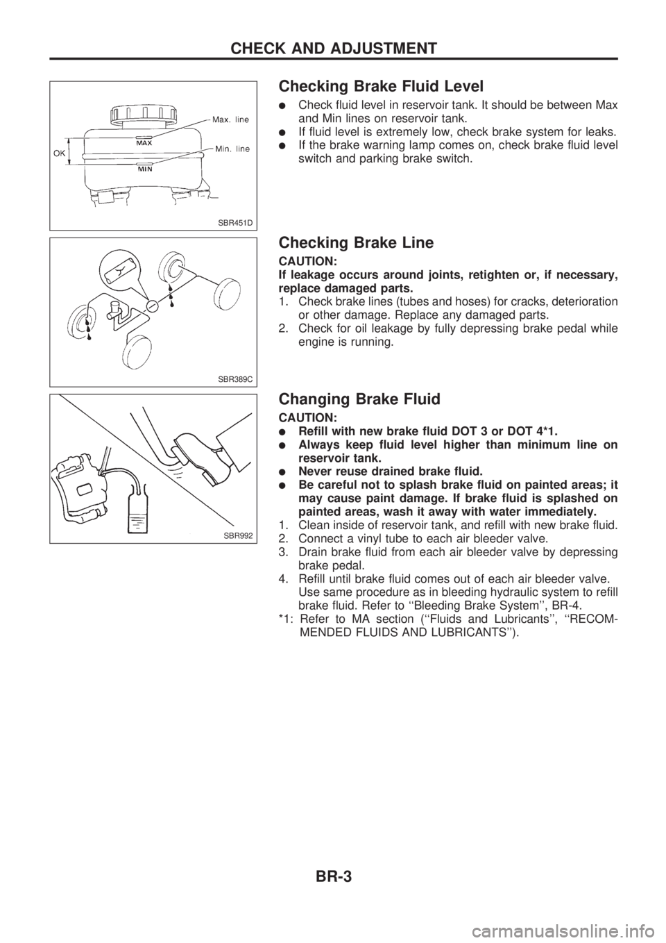
Checking Brake Fluid Level
lCheck fluid level in reservoir tank. It should be between Max
and Min lines on reservoir tank.
lIf fluid level is extremely low, check brake system for leaks.
lIf the brake warning lamp comes on, check brake fluid level
switch and parking brake switch.
Checking Brake Line
CAUTION:
If leakage occurs around joints, retighten or, if necessary,
replace damaged parts.
1. Check brake lines (tubes and hoses) for cracks, deterioration
or other damage. Replace any damaged parts.
2. Check for oil leakage by fully depressing brake pedal while
engine is running.
Changing Brake Fluid
CAUTION:
lRefill with new brake fluid DOT 3 or DOT 4*1.
lAlways keep fluid level higher than minimum line on
reservoir tank.
lNever reuse drained brake fluid.
lBe careful not to splash brake fluid on painted areas; it
may cause paint damage. If brake fluid is splashed on
painted areas, wash it away with water immediately.
1. Clean inside of reservoir tank, and refill with new brake fluid.
2. Connect a vinyl tube to each air bleeder valve.
3. Drain brake fluid from each air bleeder valve by depressing
brake pedal.
4. Refill until brake fluid comes out of each air bleeder valve.
Use same procedure as in bleeding hydraulic system to refill
brake fluid. Refer to ``Bleeding Brake System'', BR-4.
*1: Refer to MA section (``Fluids and Lubricants'', ``RECOM-
MENDED FLUIDS AND LUBRICANTS'').
SBR451D
SBR389C
SBR992
CHECK AND ADJUSTMENT
BR-3
Page 25 of 1659
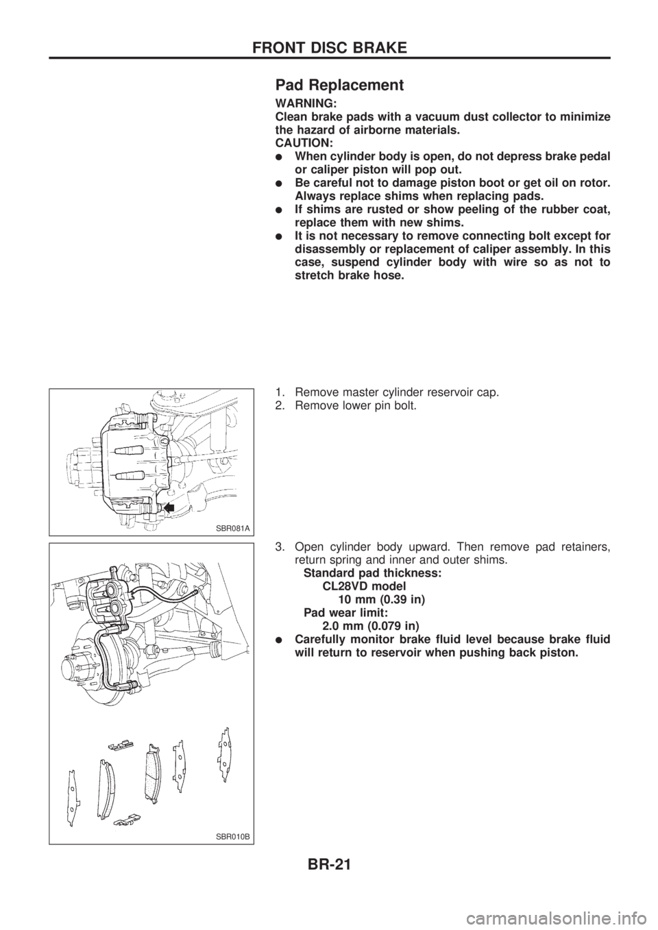
Pad Replacement
WARNING:
Clean brake pads with a vacuum dust collector to minimize
the hazard of airborne materials.
CAUTION:
lWhen cylinder body is open, do not depress brake pedal
or caliper piston will pop out.
lBe careful not to damage piston boot or get oil on rotor.
Always replace shims when replacing pads.
lIf shims are rusted or show peeling of the rubber coat,
replace them with new shims.
lIt is not necessary to remove connecting bolt except for
disassembly or replacement of caliper assembly. In this
case, suspend cylinder body with wire so as not to
stretch brake hose.
1. Remove master cylinder reservoir cap.
2. Remove lower pin bolt.
3. Open cylinder body upward. Then remove pad retainers,
return spring and inner and outer shims.
Standard pad thickness:
CL28VD model
10 mm (0.39 in)
Pad wear limit:
2.0 mm (0.079 in)
lCarefully monitor brake fluid level because brake fluid
will return to reservoir when pushing back piston.
SBR081A
SBR010B
FRONT DISC BRAKE
BR-21
Page 177 of 1659
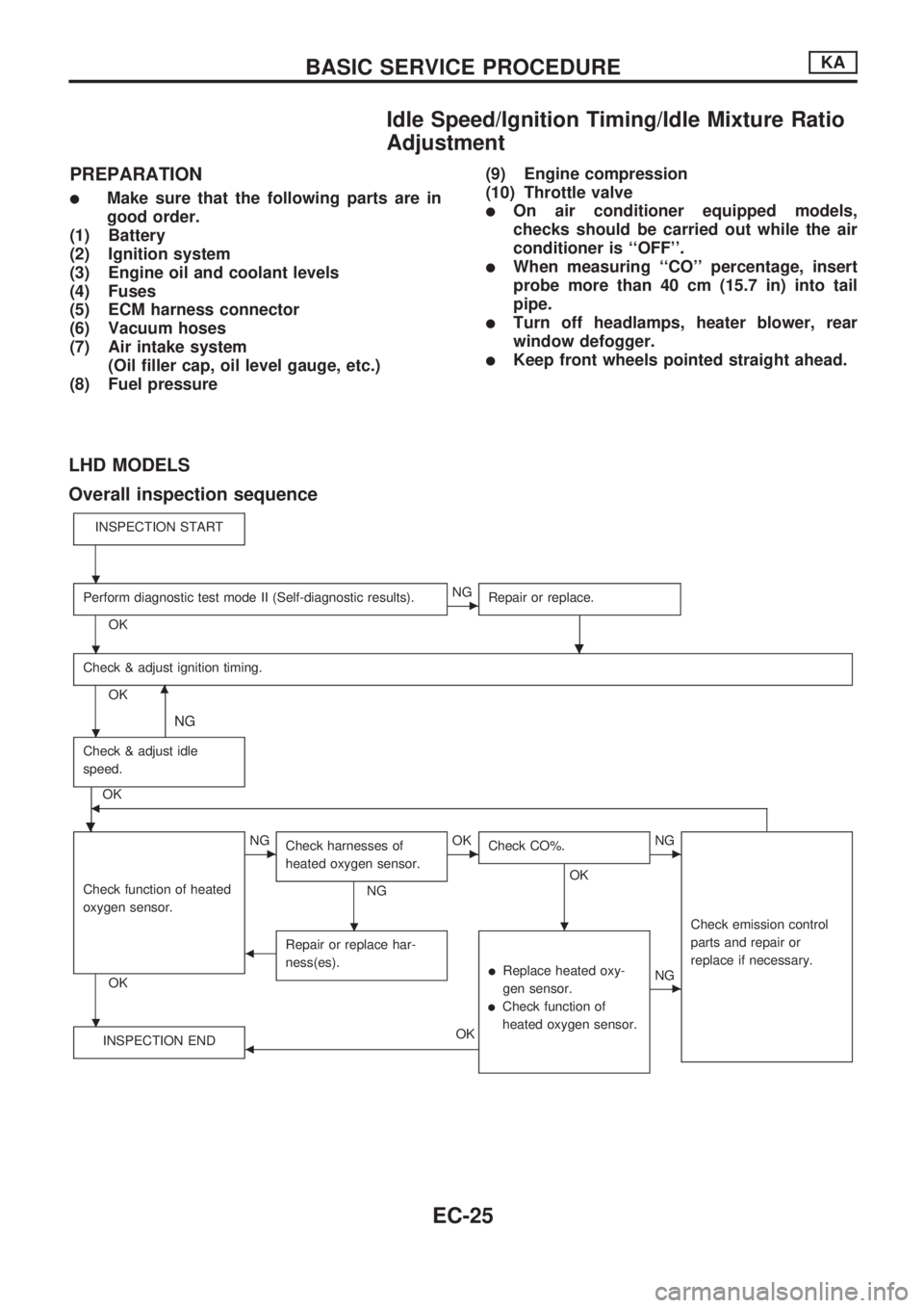
Idle Speed/Ignition Timing/Idle Mixture Ratio
Adjustment
PREPARATION
lMake sure that the following parts are in
good order.
(1) Battery
(2) Ignition system
(3) Engine oil and coolant levels
(4) Fuses
(5) ECM harness connector
(6) Vacuum hoses
(7) Air intake system
(Oil filler cap, oil level gauge, etc.)
(8) Fuel pressure(9) Engine compression
(10) Throttle valvelOn air conditioner equipped models,
checks should be carried out while the air
conditioner is ``OFF''.
lWhen measuring ``CO'' percentage, insert
probe more than 40 cm (15.7 in) into tail
pipe.
lTurn off headlamps, heater blower, rear
window defogger.
lKeep front wheels pointed straight ahead.
LHD MODELS
Overall inspection sequence
INSPECTION START
Perform diagnostic test mode II (Self-diagnostic results).
OK
cNG
Repair or replace.
.
Check & adjust ignition timing.
OKm
NG
Check & adjust idle
speed.
.
OKb
Check function of heated
oxygen sensor.
OK
cNG
Check harnesses of
heated oxygen sensor.
NG
cOK
Check CO%.
OK
.
cNG
Check emission control
parts and repair or
replace if necessary.
bRepair or replace har-
ness(es).
lReplace heated oxy-
gen sensor.
lCheck function of
heated oxygen sensor.
cNG
INSPECTION END
bOK
.
.
.
.
.
BASIC SERVICE PROCEDUREKA
EC-25
Page 215 of 1659
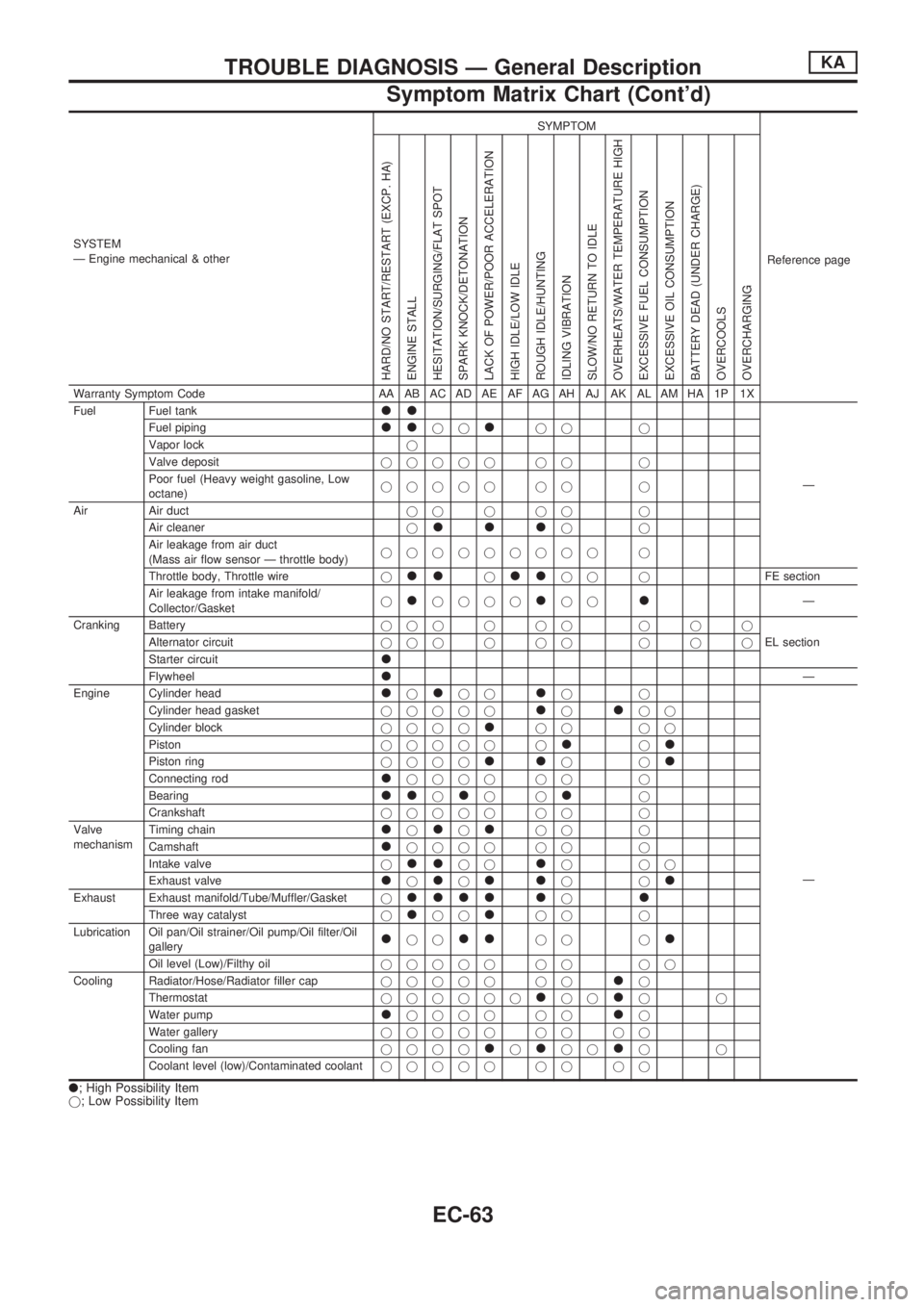
SYSTEM
Ð Engine mechanical & otherSYMPTOM
Reference page
HARD/NO START/RESTART (EXCP. HA)
ENGINE STALL
HESITATION/SURGING/FLAT SPOT
SPARK KNOCK/DETONATION
LACK OF POWER/POOR ACCELERATION
HIGH IDLE/LOW IDLE
ROUGH IDLE/HUNTING
IDLING VIBRATION
SLOW/NO RETURN TO IDLE
OVERHEATS/WATER TEMPERATURE HIGH
EXCESSIVE FUEL CONSUMPTION
EXCESSIVE OIL CONSUMPTION
BATTERY DEAD (UNDER CHARGE)
OVERCOOLS
OVERCHARGING
Warranty Symptom Code AA AB AC AD AE AF AG AH AJ AK AL AM HA 1P 1X
Fuel Fuel tank
ll
Ð Fuel piping
lljjljj j
Vapor lockj
Valve depositjjjjj jj j
Poor fuel (Heavy weight gasoline, Low
octane)jjjjj jj j
Air Air ductjjjjj j
Air cleanerj
llljj
Air leakage from air duct
(Mass air flow sensor Ð throttle body)jjjjjjjjj j
Throttle body, Throttle wirej
lljlljj jFE section
Air leakage from intake manifold/
Collector/Gasketj
ljjjjljjlÐ
Cranking Batteryjjjjjj jjj
EL section Alternator circuitjjjjjj jjj
Starter circuit
l
FlywheellÐ
Engine Cylinder head
ljljjljj
Ð Cylinder head gasketjjjjj
ljljj
Cylinder blockjjjj
ljj jj
Pistonjjjjj j
ljl
Piston ringjjjjlljjl
Connecting rodljjjj jj j
Bearing
lljljjlj
Crankshaftjjjjj jj j
Valve
mechanismTiming chain
ljljljj j
Camshaft
ljjjj jj j
Intake valvej
lljjljjj
Exhaust valve
ljljlljjl
Exhaust Exhaust manifold/Tube/Muffler/Gasketjllll ljl
Three way catalystjljjljj j
Lubrication Oil pan/Oil strainer/Oil pump/Oil filter/Oil
gallery
ljjlljj jl
Oil level (Low)/Filthy oiljjjjj jj jj
Cooling Radiator/Hose/Radiator filler capjjjjj jj
lj
Thermostatjjjjjj
ljjljj
Water pump
ljjjj jjlj
Water galleryjjjjj jj jj
Cooling fanjjjj
ljljjljj
Coolant level (low)/Contaminated coolantjjjjj jj jj
l; High Possibility Item
j; Low Possibility Item
TROUBLE DIAGNOSIS Ð General DescriptionKA
Symptom Matrix Chart (Cont'd)
EC-63
Page 258 of 1659
Overheat
ON BOARD DIAGNOSIS LOGIC
If the cooling fan or another component in the cooling system malfunctions, the engine coolant temperature
will rise.
When the engine coolant temperature reaches an abnormally high temperature condition, a malfunction is
indicated.
Diagnostic trouble
code No.Malfunction is detected when ...Check Items
(Possible Cause)
28
lEngine coolant temperature reaches an abnormally
high temperature.lCooling fan
lRadiator hose
lRadiator
lRadiator cap
lWater pump
lThermostat
For more information, refer to ``MAIN 12
CAUSES OF OVERHEATING'', EC-108.
CAUTION:
When a malfunction is indicated, be sure to replace the coolant following the procedure in MA sec-
tion (``Changing Engine Coolant'', ``ENGINE MAINTENANCE''). Also, replace the engine oil.
lFill radiator with coolant up to specified level with a filling speed of 2 liters per minute like pour-
ing coolant by kettle. Be sure to use coolant with the proper mixture ratio. Refer to MA section
(``Anti-freeze Coolant Mixture Ratio'', ``RECOMMENDED FLUIDS AND LUBRICANTS'').
lAfter refilling coolant, run engine to ensure that no water-flow noise is emitted.
OVERALL FUNCTION CHECK
WARNING:
Never remove the radiator cap when the engine is hot. Seri-
ous burns could be caused by high pressure fluid escaping
from the radiator.
Wrap a thick cloth around cap. Carefully remove the cap by
turning it a quarter turn to allow built-up pressure to escape.
Then turn the cap all the way off.
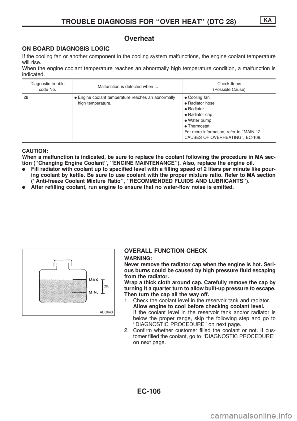
1. Check the coolant level in the reservoir tank and radiator.
Allow engine to cool before checking coolant level.
If the coolant level in the reservoir tank and/or radiator is
below the proper range, skip the following step and go to
``DIAGNOSTIC PROCEDURE'' on next page.
2. Confirm whether customer filled the coolant or not. If cus-
tomer filled the coolant, go to ``DIAGNOSTIC PROCEDURE''
on next page.
AEC640
TROUBLE DIAGNOSIS FOR ``OVER HEAT'' (DTC 28)KA
EC-106
Page 283 of 1659
Idle Air Control Valve (IACV) Ð Auxiliary Air
Control (AAC) Valve
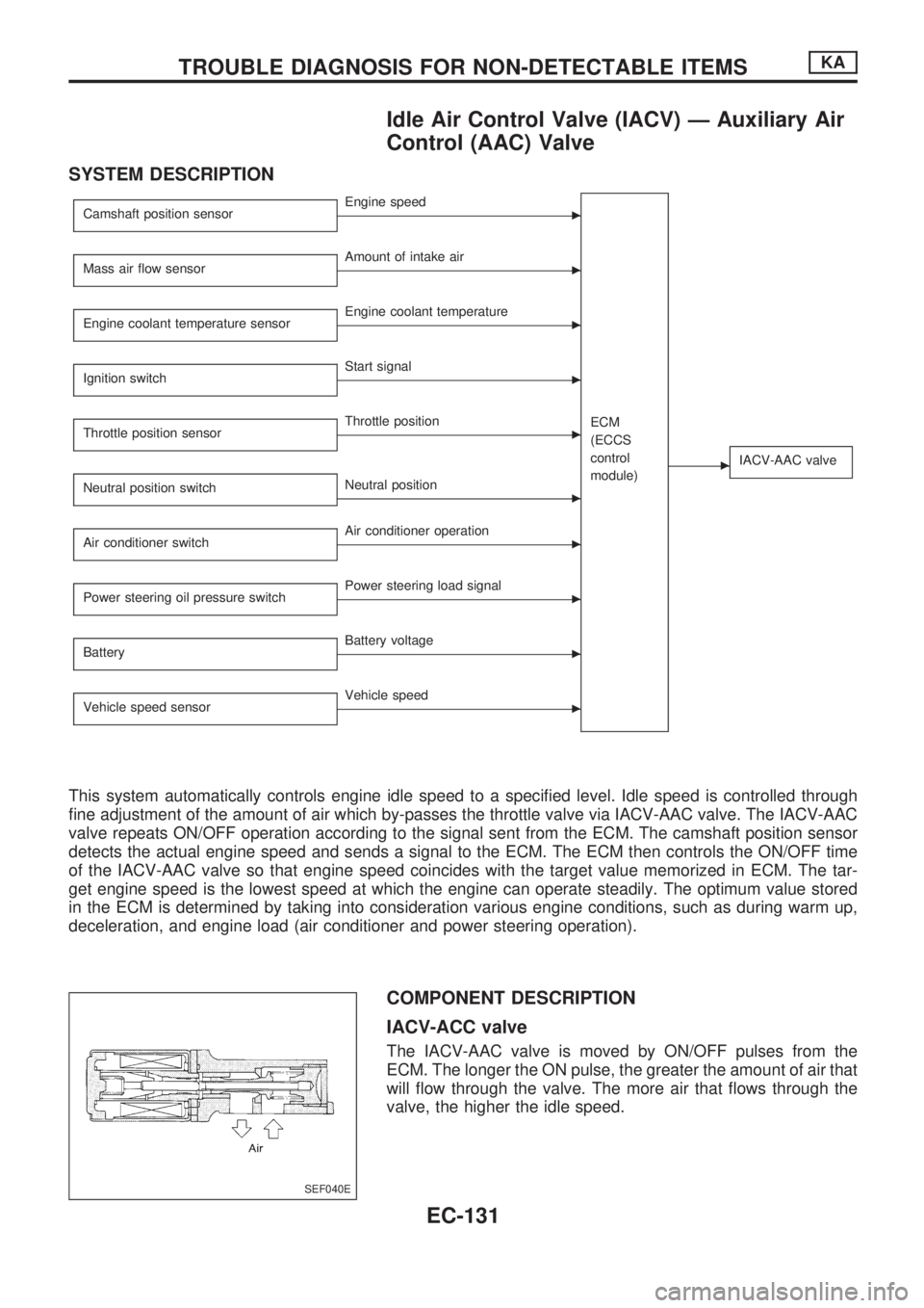
SYSTEM DESCRIPTION
Camshaft position sensorcEngine speed
ECM
(ECCS
control
module)
cIACV-AAC valve
Mass air flow sensorcAmount of intake air
Engine coolant temperature sensor
cEngine coolant temperature
Ignition switch
cStart signal
Throttle position sensor
cThrottle position
Neutral position switch
cNeutral position
Air conditioner switch
cAir conditioner operation
Power steering oil pressure switch
cPower steering load signal
Battery
cBattery voltage
Vehicle speed sensor
cVehicle speed
This system automatically controls engine idle speed to a specified level. Idle speed is controlled through
fine adjustment of the amount of air which by-passes the throttle valve via IACV-AAC valve. The IACV-AAC
valve repeats ON/OFF operation according to the signal sent from the ECM. The camshaft position sensor
detects the actual engine speed and sends a signal to the ECM. The ECM then controls the ON/OFF time
of the IACV-AAC valve so that engine speed coincides with the target value memorized in ECM. The tar-
get engine speed is the lowest speed at which the engine can operate steadily. The optimum value stored
in the ECM is determined by taking into consideration various engine conditions, such as during warm up,
deceleration, and engine load (air conditioner and power steering operation).
COMPONENT DESCRIPTION
IACV-ACC valve
The IACV-AAC valve is moved by ON/OFF pulses from the
ECM. The longer the ON pulse, the greater the amount of air that
will flow through the valve. The more air that flows through the
valve, the higher the idle speed.
SEF040E
TROUBLE DIAGNOSIS FOR NON-DETECTABLE ITEMSKA
EC-131
Page 439 of 1659
Bulb Replacement
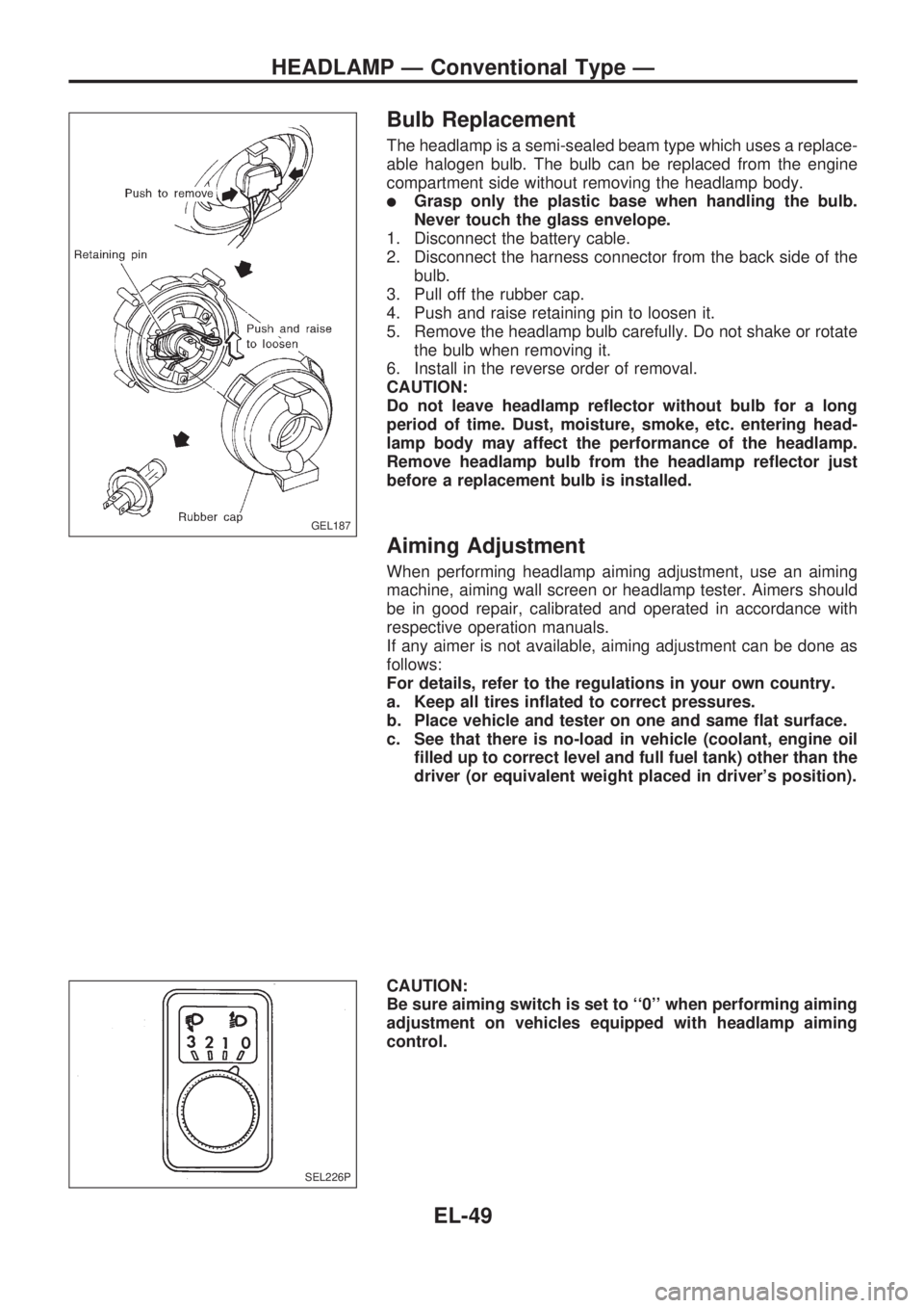
The headlamp is a semi-sealed beam type which uses a replace-
able halogen bulb. The bulb can be replaced from the engine
compartment side without removing the headlamp body.
lGrasp only the plastic base when handling the bulb.
Never touch the glass envelope.
1. Disconnect the battery cable.
2. Disconnect the harness connector from the back side of the
bulb.
3. Pull off the rubber cap.
4. Push and raise retaining pin to loosen it.
5. Remove the headlamp bulb carefully. Do not shake or rotate
the bulb when removing it.
6. Install in the reverse order of removal.
CAUTION:
Do not leave headlamp reflector without bulb for a long
period of time. Dust, moisture, smoke, etc. entering head-
lamp body may affect the performance of the headlamp.
Remove headlamp bulb from the headlamp reflector just
before a replacement bulb is installed.
Aiming Adjustment
When performing headlamp aiming adjustment, use an aiming
machine, aiming wall screen or headlamp tester. Aimers should
be in good repair, calibrated and operated in accordance with
respective operation manuals.
If any aimer is not available, aiming adjustment can be done as
follows:
For details, refer to the regulations in your own country.
a. Keep all tires inflated to correct pressures.
b. Place vehicle and tester on one and same flat surface.
c. See that there is no-load in vehicle (coolant, engine oil
filled up to correct level and full fuel tank) other than the
driver (or equivalent weight placed in driver's position).
CAUTION:
Be sure aiming switch is set to ``0'' when performing aiming
adjustment on vehicles equipped with headlamp aiming
control.
GEL187
SEL226P
HEADLAMP Ð Conventional Type Ð
EL-49
Page 807 of 1659
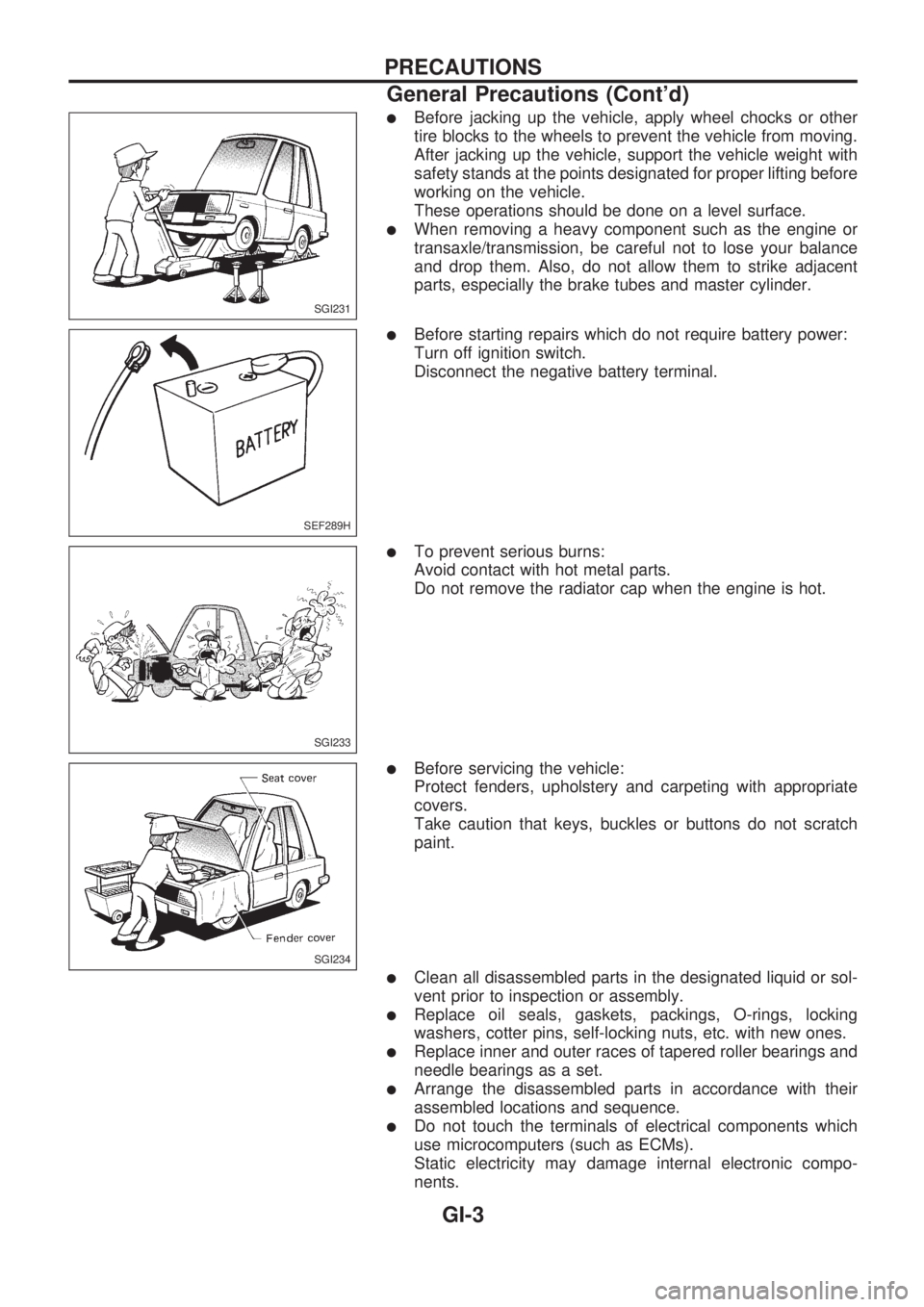
lBefore jacking up the vehicle, apply wheel chocks or other
tire blocks to the wheels to prevent the vehicle from moving.
After jacking up the vehicle, support the vehicle weight with
safety stands at the points designated for proper lifting before
working on the vehicle.
These operations should be done on a level surface.
lWhen removing a heavy component such as the engine or
transaxle/transmission, be careful not to lose your balance
and drop them. Also, do not allow them to strike adjacent
parts, especially the brake tubes and master cylinder.
lBefore starting repairs which do not require battery power:
Turn off ignition switch.
Disconnect the negative battery terminal.
lTo prevent serious burns:
Avoid contact with hot metal parts.
Do not remove the radiator cap when the engine is hot.
lBefore servicing the vehicle:
Protect fenders, upholstery and carpeting with appropriate
covers.
Take caution that keys, buckles or buttons do not scratch
paint.
lClean all disassembled parts in the designated liquid or sol-
vent prior to inspection or assembly.
lReplace oil seals, gaskets, packings, O-rings, locking
washers, cotter pins, self-locking nuts, etc. with new ones.
lReplace inner and outer races of tapered roller bearings and
needle bearings as a set.
lArrange the disassembled parts in accordance with their
assembled locations and sequence.
lDo not touch the terminals of electrical components which
use microcomputers (such as ECMs).
Static electricity may damage internal electronic compo-
nents.
SGI231
SEF289H
SGI233
SGI234
PRECAUTIONS
General Precautions (Cont'd)
GI-3
Page 808 of 1659
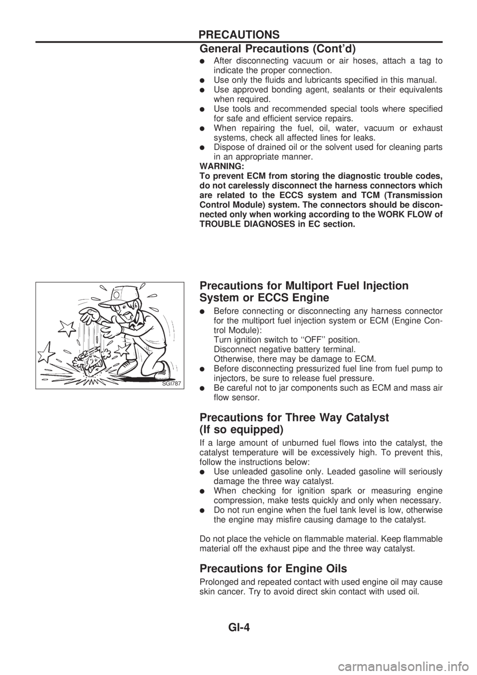
lAfter disconnecting vacuum or air hoses, attach a tag to
indicate the proper connection.
lUse only the fluids and lubricants specified in this manual.
lUse approved bonding agent, sealants or their equivalents
when required.
lUse tools and recommended special tools where specified
for safe and efficient service repairs.
lWhen repairing the fuel, oil, water, vacuum or exhaust
systems, check all affected lines for leaks.
lDispose of drained oil or the solvent used for cleaning parts
in an appropriate manner.
WARNING:
To prevent ECM from storing the diagnostic trouble codes,
do not carelessly disconnect the harness connectors which
are related to the ECCS system and TCM (Transmission
Control Module) system. The connectors should be discon-
nected only when working according to the WORK FLOW of
TROUBLE DIAGNOSES in EC section.
Precautions for Multiport Fuel Injection
System or ECCS Engine
lBefore connecting or disconnecting any harness connector
for the multiport fuel injection system or ECM (Engine Con-
trol Module):
Turn ignition switch to ``OFF'' position.
Disconnect negative battery terminal.
Otherwise, there may be damage to ECM.
lBefore disconnecting pressurized fuel line from fuel pump to
injectors, be sure to release fuel pressure.
lBe careful not to jar components such as ECM and mass air
flow sensor.
Precautions for Three Way Catalyst
(If so equipped)
If a large amount of unburned fuel flows into the catalyst, the
catalyst temperature will be excessively high. To prevent this,
follow the instructions below:
lUse unleaded gasoline only. Leaded gasoline will seriously
damage the three way catalyst.
lWhen checking for ignition spark or measuring engine
compression, make tests quickly and only when necessary.
lDo not run engine when the fuel tank level is low, otherwise
the engine may misfire causing damage to the catalyst.
Do not place the vehicle on flammable material. Keep flammable
material off the exhaust pipe and the three way catalyst.
Precautions for Engine Oils
Prolonged and repeated contact with used engine oil may cause
skin cancer. Try to avoid direct skin contact with used oil.
SGI787
PRECAUTIONS
General Precautions (Cont'd)
GI-4
Page 867 of 1659
HLC - Wiring diagram ................................ EL-130
HORN - Wiring diagram ............................. EL-132
H/SEAT - Wiring diagram........................... EL-152
Harness connector ......................................... EL-2
Harness connector inspection ...................... GI-18
Harness layout ........................................... EL-220
Hazard warning lamp ................................... EL-74
Headlamp ..................................................... EL-44
Headlamp aiming control ............................. EL-63
Headlamp leveler - See Headlamp
aiming control ........................................... EL-63
Headlamp washer ...................................... EL-130
Heated oxygen sensor (HO2S) ................. EC-123
Heated oxygen sensor heater ................... EC-127
Heated oxygen sensor inspection ............... MA-22
Heated seat .................................................. BT-32
Heated seat ................................................ EL-152
Height (Dimensions) ..................................... GI-44
Hood ............................................................... BT-5
Horn ............................................................ EL-132
How to erase DTC for ECCS OBD
system ...................................................... EC-36
I
IACV-AAC valve .................................EC-131, 135
IACV-FICD solenoid valve
(KA24 engine) ........................................ EC-168
IACV-FICD solenoid valve
(TD25 engine) ........................................ EC-231
IATS - Wiring diagram ............................... EC-110
IGN/SG - Wiring diagram .......................... EC-101
ILL - Wiring diagram..................................... EL-81
INJECT - Wiring diagram .......................... EC-144
INT/L - Wiring diagram ................................. EL-85
Identification plate ......................................... GI-42
Idle mixture ratio .......................................... EC-25
Idle speed .................................................... EC-25
Idle speed inspection .................................. MA-30
Ignition coil ................................................. EC-105
Ignition timing............................................... EC-25
Ignition wire inspection ................................ MA-21
Illumination ................................................... EL-81
Injection nozzle inspection .......................... MA-29
Injection nozzle .......................................... EC-186
Injector ............................................... EC-144, 148
Injector removal and installation .................. EC-23
Instrument panel .......................................... BT-12
Intake air temperature sensor ................... EC-109
Intake door control linkage
adjustment................................................ HA-47
Intake manifold .............................................. EM-9
Interior lamp ................................................. EL-85
Interior .......................................................... BT-15
J
Jacking points ................................................GI-47Journal bearing assembly
(propeller shaft) ........................................ PD-11
Journal bearing disassembly
(propeller shaft) ........................................ PD-10
Jump seat..................................................... BT-34
K
Keyless entry system - See Multi-remote
control system .............................................EL-173
Knuckle spindle ............................................ FA-18
L
LSV (Load sensing valve)...............................BR-7
Leaf spring (rear) ......................................... RA-13
Length (Dimensions) ..................................... GI-44
License lamp ................................................ EL-66
Lifting points .................................................. GI-47
Limited slip diff. adjustment (C200) ............. PD-41
Limited slip diff. adjustment (H233B) .......... PD-63
Limited slip diff. assembly (C200) ............... PD-43
Limited slip diff. assembly (H233B) ............. PD-64
Limited slip diff. disassembly (C200)........... PD-39
Limited slip diff. disassembly (H233B) ........ PD-61
Limited slip diff. inspection (C200) .............. PD-40
Limited slip diff. inspection (H233B) ............ PD-62
Liquid gasket application ............................... EM-1
Location of electrical units.......................... EL-217
Lock, door .................................................... BT-10
Lubricant (R134a) A/C ................................. HA-50
Lubricants .................................................... MA-12
Lubrication circuit (engine)
(KA24 engine) ............................................ LC-3
Lubrication circuit (engine)
(TD25 engine) .......................................... LC-12
Lubrication-locks, hinges and hood
latches ..................................................... MA-39
M
M/T major overhaul (FS5R30A) ...................MT-35
M/T major overhaul (FS5W71C) ................. MT-14
M/T removal and installation ....................... MT-11
MAFS - Wiring diagram ............................... EC-91
MAIN - Wiring diagram ................................ EC-76
METER - Wiring diagram ............................. EL-90
MIL & Data link connectors ....................... EC-173
MIRROR - Wiring diagram ......................... EL-150
MULTI - Wiring diagram ............................. EL-175
Main drive gear (M/T) (FS5R30A)............... MT-36
Main drive gear (M/T) (FS5W71C).............. MT-15
Main gear (Transfer) ...................................... TF-9
Mainshaft (M/T) (FS5R30A) ........................ MT-36
Mainshaft (M/T) (FS5W71C) ....................... MT-15
Mainshaft (Transfer) ....................................... TF-9
Maintenance (engine) (KA24 engine) ......... MA-15
ALPHABETICAL INDEX
IDX-5