fuel NISSAN PICK-UP 1998 Repair Manual
[x] Cancel search | Manufacturer: NISSAN, Model Year: 1998, Model line: PICK-UP, Model: NISSAN PICK-UP 1998Pages: 1659, PDF Size: 53.39 MB
Page 1 of 1659
GENERAL INFORMATIONGI
MAINTENANCEMA
ENGINE MECHANICALEM
ENGINE LUBRICATION &
COOLING SYSTEMSLC
ENGINE CONTROL SYSTEMEC
ACCELERATOR CONTROL, FUEL &
EXHAUST SYSTEMSFE
CLUTCHCL
MANUAL TRANSAXLEMT
TRANSFERTF
PROPELLER SHAFT &
DIFFERENTIAL CARRIERPD
FRONT AXLE & FRONT SUSPENSIONFA
REAR AXLE & REAR SUSPENSIONRA
BRAKE SYSTEMBR
STEERING SYSTEMST
RESTRAINT SYSTEMRS
BODY & TRIMBT
HEATER & AIR CONDITIONERHA
ELECTRICAL SYSTEMEL
ALPHABETICAL INDEXIDX
PICKUP
MODEL D22 SERIES
Edition: February 1998
Printing: May 1998 (01)
Publication No.: SM8E-0D22E0E
NISSAN EUROPE S.A.S.
1998 NISSAN EUROPE S.A.S. Printed in the Netherlands
Not to be reproduced in whole or in part without the prior written permission of Nissan Europe S.A.S., Paris, France.
QUICK REFERENCE INDEX
Page 13 of 1659
INSPECTION
1. Ensure vehicle is unladen condition*.
* Fuel, radiator coolant and engine oil full. Spare tire, jack,
hand tools and mats in designated positions.
2. Have a driver sit in the driver's seat and one person sit on
the rear of the vehicle. Then have the person on the rear of
the vehicle slowly get off. This is necessary to stabilize sus-
pension deflection.
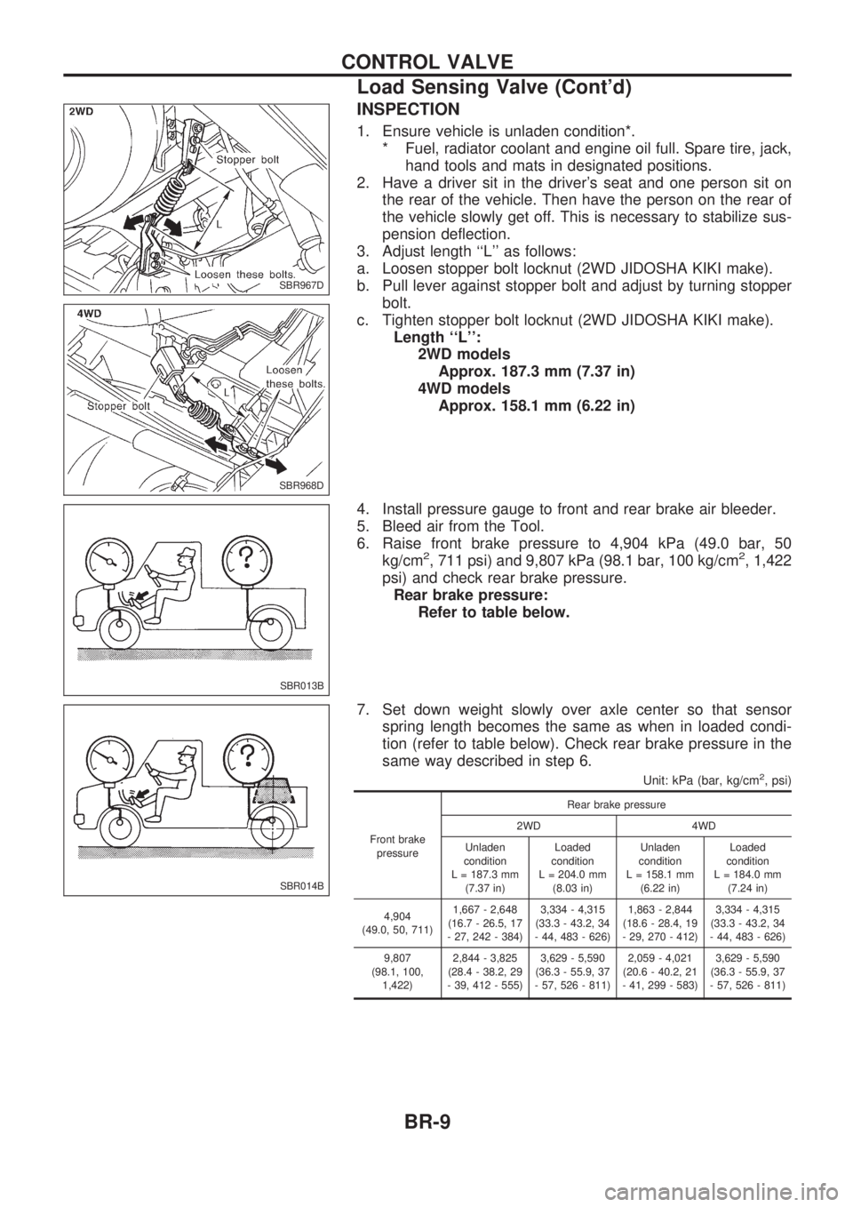
3. Adjust length ``L'' as follows:
a. Loosen stopper bolt locknut (2WD JIDOSHA KIKI make).
b. Pull lever against stopper bolt and adjust by turning stopper
bolt.
c. Tighten stopper bolt locknut (2WD JIDOSHA KIKI make).
Length ``L'':
2WD models
Approx. 187.3 mm (7.37 in)
4WD models
Approx. 158.1 mm (6.22 in)
4. Install pressure gauge to front and rear brake air bleeder.
5. Bleed air from the Tool.
6. Raise front brake pressure to 4,904 kPa (49.0 bar, 50
kg/cm
2, 711 psi) and 9,807 kPa (98.1 bar, 100 kg/cm2, 1,422
psi) and check rear brake pressure.
Rear brake pressure:
Refer to table below.
7. Set down weight slowly over axle center so that sensor
spring length becomes the same as when in loaded condi-
tion (refer to table below). Check rear brake pressure in the
same way described in step 6.
Unit: kPa (bar, kg/cm2, psi)
Front brake
pressureRear brake pressure
2WD 4WD
Unladen
condition
L = 187.3 mm
(7.37 in)Loaded
condition
L = 204.0 mm
(8.03 in)Unladen
condition
L = 158.1 mm
(6.22 in)Loaded
condition
L = 184.0 mm
(7.24 in)
4,904
(49.0, 50, 711)1,667 - 2,648
(16.7 - 26.5, 17
- 27, 242 - 384)3,334 - 4,315
(33.3 - 43.2, 34
- 44, 483 - 626)1,863 - 2,844
(18.6 - 28.4, 19
- 29, 270 - 412)3,334 - 4,315
(33.3 - 43.2, 34
- 44, 483 - 626)
9,807
(98.1, 100,
1,422)2,844 - 3,825
(28.4 - 38.2, 29
- 39, 412 - 555)3,629 - 5,590
(36.3 - 55.9, 37
- 57, 526 - 811)2,059 - 4,021
(20.6 - 40.2, 21
- 41, 299 - 583)3,629 - 5,590
(36.3 - 55.9, 37
- 57, 526 - 811)
SBR967D
SBR968D
SBR013B
SBR014B
CONTROL VALVE
Load Sensing Valve (Cont'd)
BR-9
Page 140 of 1659
Removal
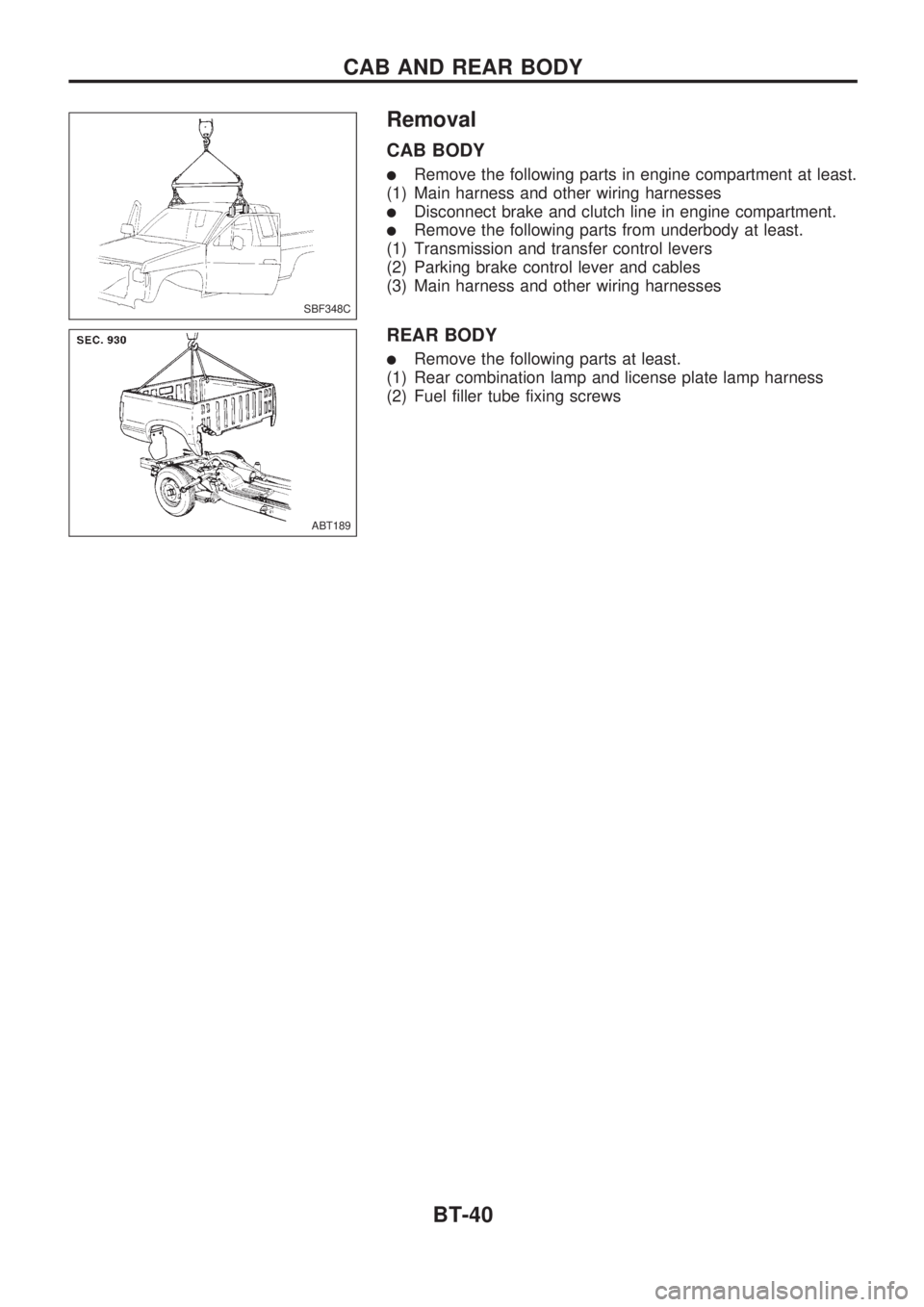
CAB BODY
lRemove the following parts in engine compartment at least.
(1) Main harness and other wiring harnesses
lDisconnect brake and clutch line in engine compartment.
lRemove the following parts from underbody at least.
(1) Transmission and transfer control levers
(2) Parking brake control lever and cables
(3) Main harness and other wiring harnesses
REAR BODY
lRemove the following parts at least.
(1) Rear combination lamp and license plate lamp harness
(2) Fuel filler tube fixing screws
SBF348C
ABT189
CAB AND REAR BODY
BT-40
Page 150 of 1659
ENGINE CONTROL SYSTEM
SECTION
EC
CONTENTS
DIAGNOSTIC TROUBLE CODE INDEX................... 1
Alphabetical & Numerical Index for DTC
(KA engine) ............................................................ 1
PRECAUTIONS AND PREPARATION..................... 2
Special Service Tools ............................................ 2
Commercial Service Tool....................................... 4
Supplemental Restraint System (SRS) ``AIR
BAG'' (4WD models).............................................. 4
Supplemental Restraint System (SRS) ``AIR
BAG'' (2WD models).............................................. 4
KA
PRECAUTIONS AND PREPARATION..................... 5
Engine Fuel & Emission Control System .............. 5
Precautions ............................................................ 6
ENGINE AND EMISSION CONTROL OVERALL
SYSTEM..................................................................... 8
Circuit Diagram ...................................................... 8
System Diagram .................................................... 9
ECCS Component Parts Location ....................... 10
Vacuum Hose Drawing ........................................ 12
System Chart ....................................................... 13
ENGINE AND EMISSION BASIC CONTROL
SYSTEM DESCRIPTION..................................... 14
Multiport Fuel Injection (MFI) System.................. 14
Distributor Ignition (DI) System............................ 17
Air Conditioning Cut Control ................................ 18
Fuel Cut Control (at no load & high engine
speed) .................................................................. 18
EVAPORATIVE EMISSION SYSTEM..................... 19
Description ........................................................... 19
Inspection ............................................................. 19POSITIVE CRANKCASE VENTILATION................ 21
Description ........................................................... 21
Inspection ............................................................. 21
BASIC SERVICE PROCEDURE............................. 22
Fuel Pressure Release ........................................ 22
Fuel Pressure Check ........................................... 22
Injector Removal and Installation ........................ 23
Fast Idle Cam (FIC) Inspection and
Adjustment ........................................................... 24
Idle Speed/Ignition Timing/Idle Mixture Ratio
Adjustment ........................................................... 25
ON BOARD DIAGNOSTIC SYSTEM
DESCRIPTION......................................................... 36
Introduction .......................................................... 36
Diagnostic Trouble Code (DTC) .......................... 36
Malfunction Indicator Lamp (MIL) ........................ 38
CONSULT ............................................................ 45
TROUBLE DIAGNOSIS - Introduction.................. 54
Introduction .......................................................... 54
Diagnostic Worksheet .......................................... 54
TROUBLE DIAGNOSIS - Work Flow..................... 56
Work Flow ............................................................ 56
Description for Work Flow ................................... 57
TROUBLE DIAGNOSIS - Basic Inspection.......... 58
Basic Inspection ................................................... 58
TROUBLE DIAGNOSIS - General Description..... 61
Fail-Safe Chart ..................................................... 61
Symptom Matrix Chart ......................................... 62
CONSULT Reference Value in Data Monitor
Mode .................................................................... 64
Major Sensor Reference Graph in Data
Monitor Mode ....................................................... 66
ECM Terminals and Reference Value ................. 68
EC
Page 151 of 1659
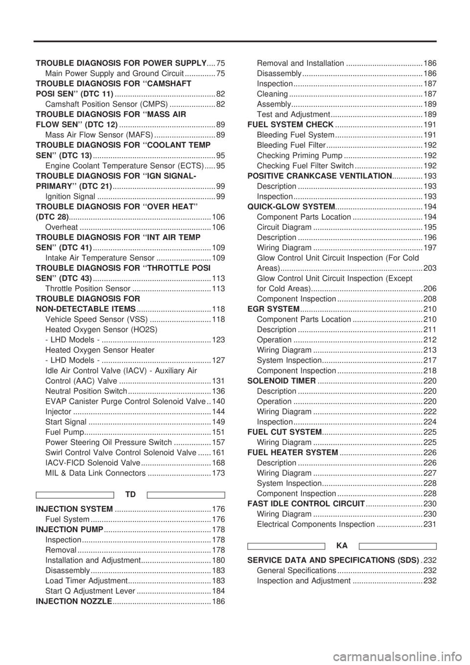
TROUBLE DIAGNOSIS FOR POWER SUPPLY.... 75
Main Power Supply and Ground Circuit .............. 75
TROUBLE DIAGNOSIS FOR ``CAMSHAFT
POSI SEN'' (DTC 11).............................................. 82
Camshaft Position Sensor (CMPS) ..................... 82
TROUBLE DIAGNOSIS FOR ``MASS AIR
FLOW SEN'' (DTC 12)............................................ 89
Mass Air Flow Sensor (MAFS) ............................ 89
TROUBLE DIAGNOSIS FOR ``COOLANT TEMP
SEN'' (DTC 13)........................................................ 95
Engine Coolant Temperature Sensor (ECTS) ..... 95
TROUBLE DIAGNOSIS FOR ``IGN SIGNAL-
PRIMARY'' (DTC 21)............................................... 99
Ignition Signal ...................................................... 99
TROUBLE DIAGNOSIS FOR ``OVER HEAT''
(DTC 28)................................................................. 106
Overheat ............................................................ 106
TROUBLE DIAGNOSIS FOR ``INT AIR TEMP
SEN'' (DTC 41)...................................................... 109
Intake Air Temperature Sensor ......................... 109
TROUBLE DIAGNOSIS FOR ``THROTTLE POSI
SEN'' (DTC 43)...................................................... 113
Throttle Position Sensor .................................... 113
TROUBLE DIAGNOSIS FOR
NON-DETECTABLE ITEMS.................................. 118
Vehicle Speed Sensor (VSS) ............................ 118
Heated Oxygen Sensor (HO2S)
- LHD Models - .................................................. 123
Heated Oxygen Sensor Heater
- LHD Models - .................................................. 127
Idle Air Control Valve (IACV) - Auxiliary Air
Control (AAC) Valve .......................................... 131
Neutral Position Switch ...................................... 136
EVAP Canister Purge Control Solenoid Valve .. 140
Injector ............................................................... 144
Start Signal ........................................................ 149
Fuel Pump.......................................................... 151
Power Steering Oil Pressure Switch ................. 157
Swirl Control Valve Control Solenoid Valve ...... 161
IACV-FICD Solenoid Valve ................................ 168
MIL & Data Link Connectors ............................. 173
TD
INJECTION SYSTEM............................................ 176
Fuel System ....................................................... 176
INJECTION PUMP................................................. 178
Inspection ........................................................... 178
Removal ............................................................. 178
Installation and Adjustment................................ 180
Disassembly ....................................................... 183
Load Timer Adjustment...................................... 183
Start Q Adjustment Lever .................................. 184
INJECTION NOZZLE............................................. 186Removal and Installation ................................... 186
Disassembly ....................................................... 186
Inspection ........................................................... 187
Cleaning ............................................................. 187
Assembly............................................................ 189
Test and Adjustment .......................................... 189
FUEL SYSTEM CHECK........................................ 191
Bleeding Fuel System ........................................ 191
Bleeding Fuel Filter ............................................ 192
Checking Priming Pump .................................... 192
Checking Fuel Filter Switch ............................... 192
POSITIVE CRANKCASE VENTILATION.............. 193
Description ......................................................... 193
Inspection ........................................................... 193
QUICK-GLOW SYSTEM........................................ 194
Component Parts Location ................................ 194
Circuit Diagram .................................................. 195
Description ......................................................... 196
Wiring Diagram .................................................. 197
Glow Control Unit Circuit Inspection (For Cold
Areas)................................................................. 203
Glow Control Unit Circuit Inspection (Except
for Cold Areas)................................................... 206
Component Inspection ....................................... 208
EGR SYSTEM........................................................ 210
Component Parts Location ................................ 210
Description ......................................................... 211
Operation ........................................................... 212
Wiring Diagram .................................................. 213
System Inspection.............................................. 217
Component Inspection ....................................... 218
SOLENOID TIMER................................................ 220
Description ......................................................... 220
Operation ........................................................... 220
Wiring Diagram .................................................. 222
Inspection ........................................................... 224
FUEL CUT SYSTEM.............................................. 225
Wiring Diagram .................................................. 225
FUEL HEATER SYSTEM...................................... 226
Description ......................................................... 226
Wiring Diagram .................................................. 227
System Inspection.............................................. 228
Component Inspection ....................................... 228
FAST IDLE CONTROL CIRCUIT.......................... 230
Wiring Diagram .................................................. 230
Electrical Components Inspection ..................... 231
KA
SERVICE DATA AND SPECIFICATIONS (SDS). 232
General Specifications ....................................... 232
Inspection and Adjustment ................................ 232
Page 156 of 1659
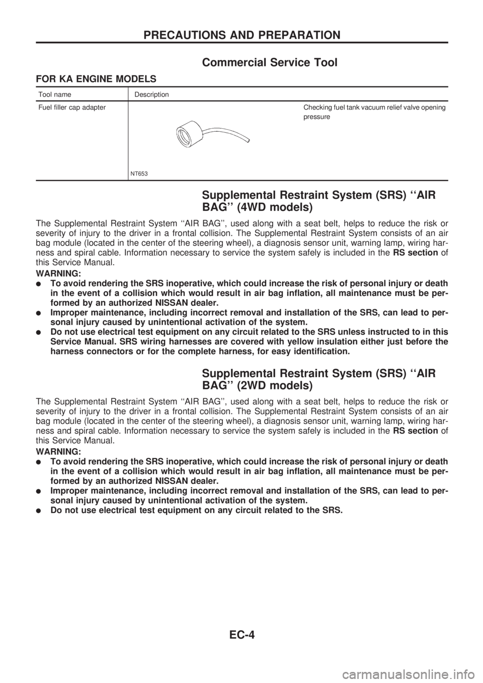
Commercial Service Tool
FOR KA ENGINE MODELS
Tool name Description
Fuel filler cap adapter
NT653
Checking fuel tank vacuum relief valve opening
pressure
Supplemental Restraint System (SRS) ``AIR
BAG'' (4WD models)
The Supplemental Restraint System ``AIR BAG'', used along with a seat belt, helps to reduce the risk or
severity of injury to the driver in a frontal collision. The Supplemental Restraint System consists of an air
bag module (located in the center of the steering wheel), a diagnosis sensor unit, warning lamp, wiring har-
ness and spiral cable. Information necessary to service the system safely is included in theRS sectionof
this Service Manual.
WARNING:
lTo avoid rendering the SRS inoperative, which could increase the risk of personal injury or death
in the event of a collision which would result in air bag inflation, all maintenance must be per-
formed by an authorized NISSAN dealer.
lImproper maintenance, including incorrect removal and installation of the SRS, can lead to per-
sonal injury caused by unintentional activation of the system.
lDo not use electrical test equipment on any circuit related to the SRS unless instructed to in this
Service Manual. SRS wiring harnesses are covered with yellow insulation either just before the
harness connectors or for the complete harness, for easy identification.
Supplemental Restraint System (SRS) ``AIR
BAG'' (2WD models)
The Supplemental Restraint System ``AIR BAG'', used along with a seat belt, helps to reduce the risk or
severity of injury to the driver in a frontal collision. The Supplemental Restraint System consists of an air
bag module (located in the center of the steering wheel), a diagnosis sensor unit, warning lamp, wiring har-
ness and spiral cable. Information necessary to service the system safely is included in theRS sectionof
this Service Manual.
WARNING:
lTo avoid rendering the SRS inoperative, which could increase the risk of personal injury or death
in the event of a collision which would result in air bag inflation, all maintenance must be per-
formed by an authorized NISSAN dealer.
lImproper maintenance, including incorrect removal and installation of the SRS, can lead to per-
sonal injury caused by unintentional activation of the system.
lDo not use electrical test equipment on any circuit related to the SRS.
PRECAUTIONS AND PREPARATION
EC-4
Page 157 of 1659
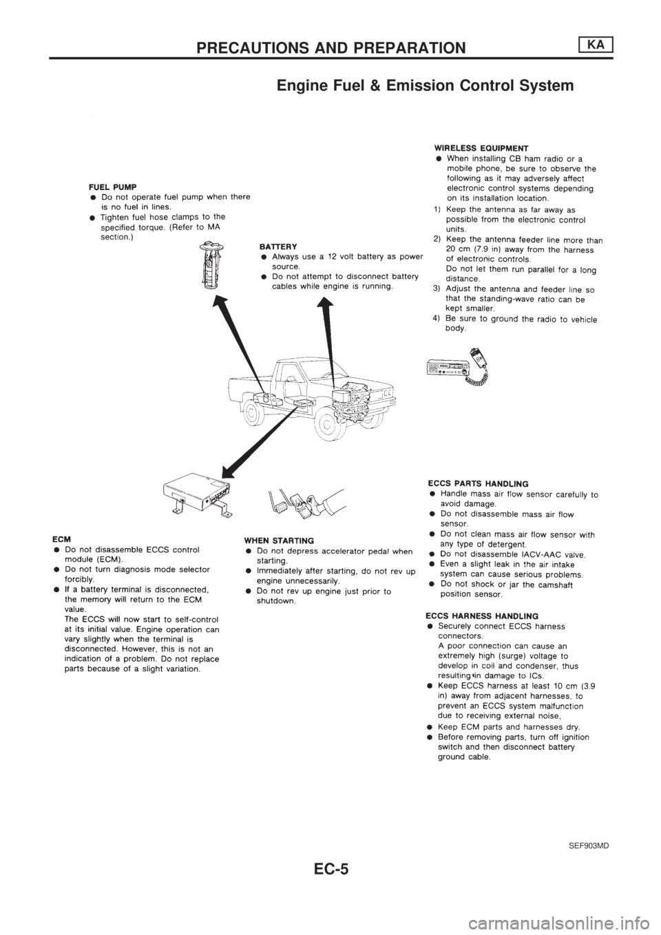
Engine Fuel & Emission Control System
SEF903MD
PRECAUTIONS AND PREPARATIONKA
EC-5
Page 164 of 1659
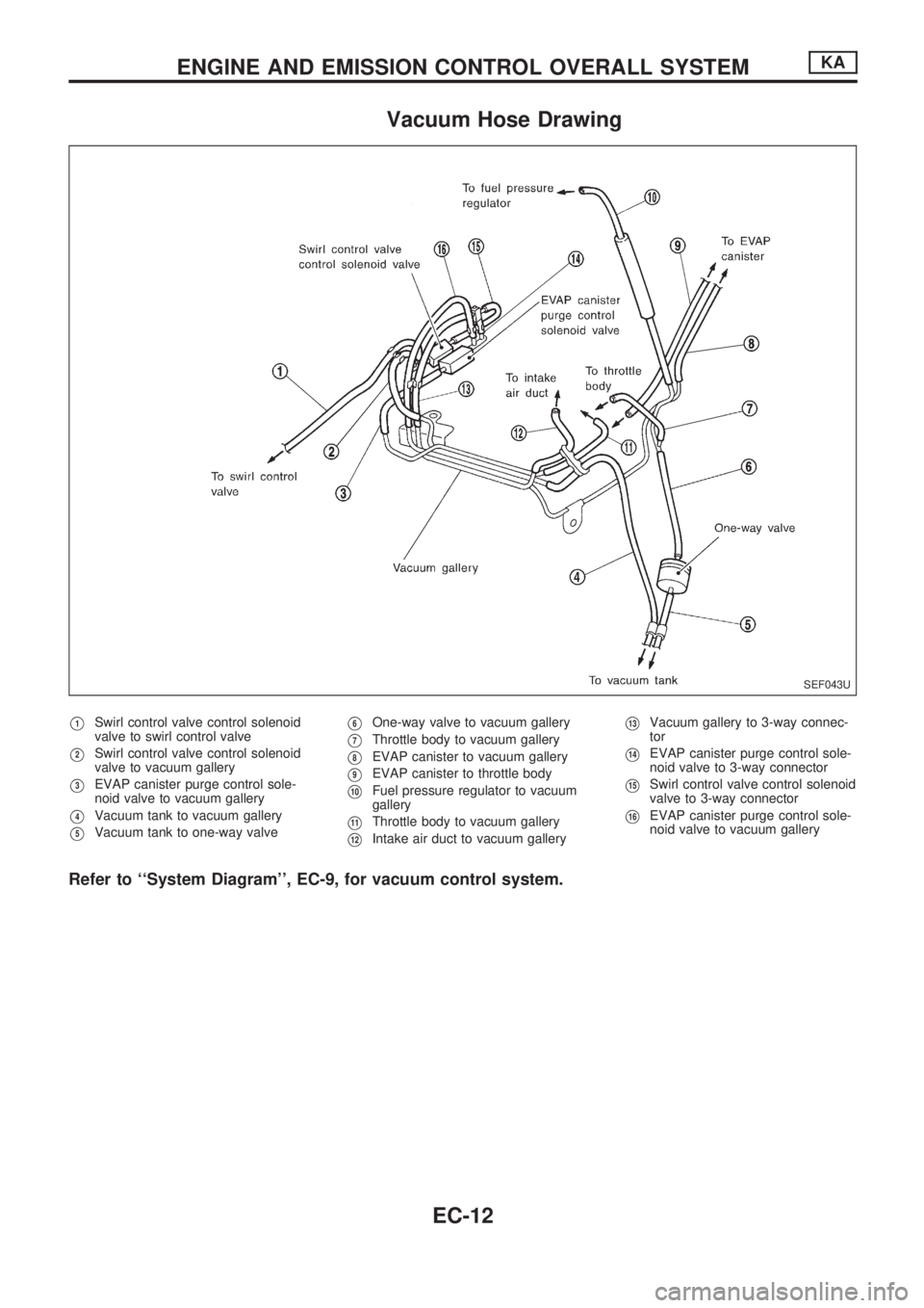
Vacuum Hose Drawing
V1Swirl control valve control solenoid
valve to swirl control valve
V2Swirl control valve control solenoid
valve to vacuum gallery
V3EVAP canister purge control sole-
noid valve to vacuum gallery
V4Vacuum tank to vacuum gallery
V5Vacuum tank to one-way valve
V6One-way valve to vacuum gallery
V7Throttle body to vacuum gallery
V8EVAP canister to vacuum gallery
V9EVAP canister to throttle body
V10Fuel pressure regulator to vacuum
gallery
V11Throttle body to vacuum gallery
V12Intake air duct to vacuum gallery
V13Vacuum gallery to 3-way connec-
tor
V14EVAP canister purge control sole-
noid valve to 3-way connector
V15Swirl control valve control solenoid
valve to 3-way connector
V16EVAP canister purge control sole-
noid valve to vacuum gallery
Refer to ``System Diagram'', EC-9, for vacuum control system.
SEF043U
ENGINE AND EMISSION CONTROL OVERALL SYSTEMKA
EC-12
Page 165 of 1659
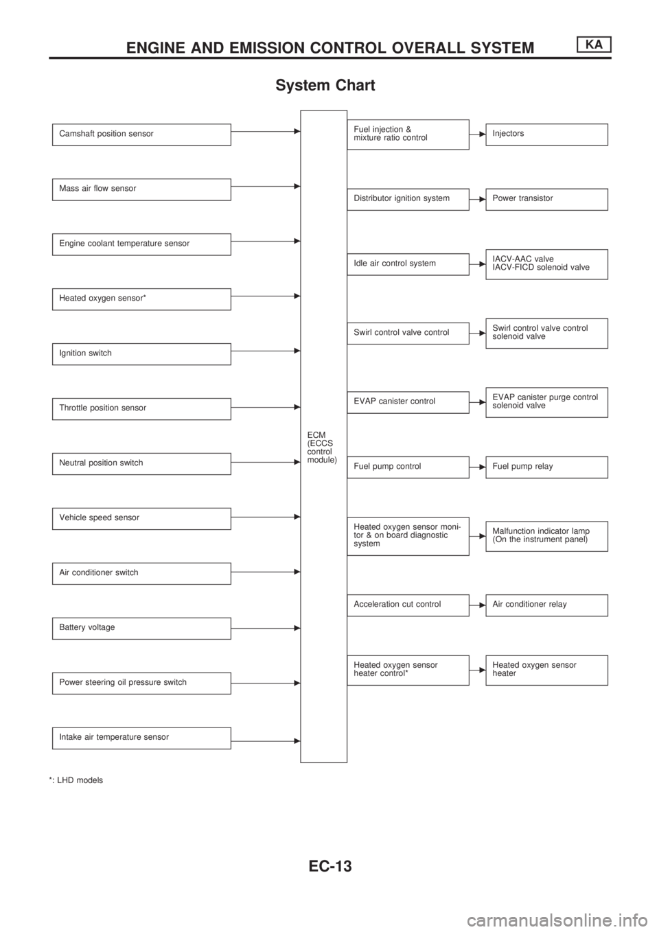
System Chart
Camshaft position sensorc
ECM
(ECCS
control
module)
Mass air flow sensorc
Engine coolant temperature sensorc
Heated oxygen sensor*c
Ignition switchc
Throttle position sensorc
Neutral position switchc
Vehicle speed sensorc
Air conditioner switchc
Battery voltagec
Power steering oil pressure switchc
Intake air temperature sensorc
*: LHD models
Fuel injection &
mixture ratio controlcInjectors
Distributor ignition systemcPower transistor
Idle air control systemcIACV-AAC valve
IACV-FICD solenoid valve
Swirl control valve controlcSwirl control valve control
solenoid valve
EVAP canister controlcEVAP canister purge control
solenoid valve
Fuel pump controlcFuel pump relay
Heated oxygen sensor moni-
tor & on board diagnostic
systemcMalfunction indicator lamp
(On the instrument panel)
Acceleration cut controlcAir conditioner relay
Heated oxygen sensor
heater control*cHeated oxygen sensor
heater
ENGINE AND EMISSION CONTROL OVERALL SYSTEMKA
EC-13
Page 166 of 1659
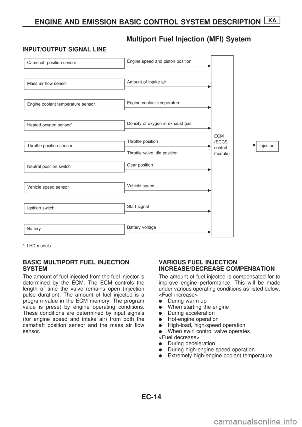
Multiport Fuel Injection (MFI) System
INPUT/OUTPUT SIGNAL LINE
Camshaft position sensorcEngine speed and piston position
ECM
(ECCS
control
module)
cInjector
Mass air flow sensorcAmount of intake air
Engine coolant temperature sensor
cEngine coolant temperature
Heated oxygen sensor*
cDensity of oxygen in exhaust gas
Throttle position sensor
cThrottle position
Throttle valve idle position
Neutral position switch
cGear position
Vehicle speed sensor
cVehicle speed
Ignition switch
cStart signal
Battery
cBattery voltage
*: LHD models
BASIC MULTIPORT FUEL INJECTION
SYSTEM
The amount of fuel injected from the fuel injector is
determined by the ECM. The ECM controls the
length of time the valve remains open (injection
pulse duration). The amount of fuel injected is a
program value in the ECM memory. The program
value is preset by engine operating conditions.
These conditions are determined by input signals
(for engine speed and intake air) from both the
camshaft position sensor and the mass air flow
sensor.
VARIOUS FUEL INJECTION
INCREASE/DECREASE COMPENSATION
The amount of fuel injected is compensated for to
improve engine performance. This will be made
under various operating conditions as listed below.
lDuring warm-up
lWhen starting the engine
lDuring acceleration
lHot-engine operation
lHigh-load, high-speed operation
lWhen swirl control valve operates
lDuring deceleration
lDuring high-engine speed operation
lExtremely high-engine coolant temperature
ENGINE AND EMISSION BASIC CONTROL SYSTEM DESCRIPTIONKA
EC-14