sensor NISSAN PICK-UP 1999 Workshop Manual
[x] Cancel search | Manufacturer: NISSAN, Model Year: 1999, Model line: PICK-UP, Model: NISSAN PICK-UP 1999Pages: 666, PDF Size: 16.21 MB
Page 533 of 666
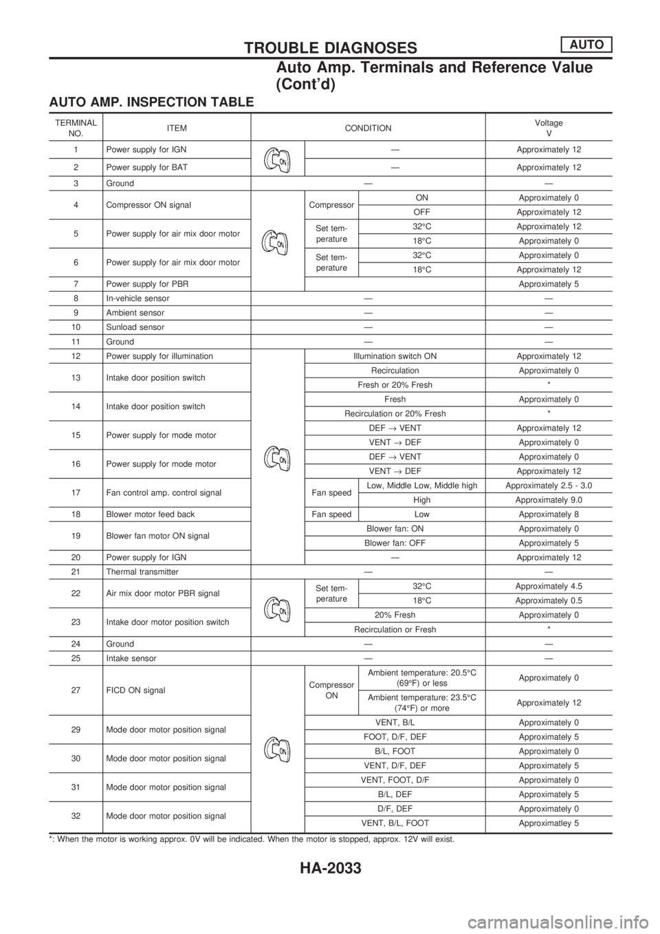
AUTO AMP. INSPECTION TABLE
TERMINAL
NO.ITEM CONDITIONVoltage
V
1 Power supply for IGN
Ð Approximately 12
2 Power supply for BAT Ð Approximately 12
3 Ground Ð Ð
4 Compressor ON signal
CompressorON Approximately 0
OFF Approximately 12
5 Power supply for air mix door motorSet tem-
perature32ÉC Approximately 12
18ÉC Approximately 0
6 Power supply for air mix door motorSet tem-
perature32ÉC Approximately 0
18ÉC Approximately 12
7 Power supply for PBRApproximately 5
8 In-vehicle sensor Ð Ð
9 Ambient sensor Ð Ð
10 Sunload sensor Ð Ð
11 Ground Ð Ð
12 Power supply for illumination
Illumination switch ON Approximately 12
13 Intake door position switchRecirculation Approximately 0
Fresh or 20% Fresh *
14 Intake door position switchFresh Approximately 0
Recirculation or 20% Fresh *
15 Power supply for mode motorDEF®VENT Approximately 12
VENT®DEF Approximately 0
16 Power supply for mode motorDEF®VENT Approximately 0
VENT®DEF Approximately 12
17 Fan control amp. control signal Fan speedLow, Middle Low, Middle high Approximately 2.5 - 3.0
High Approximately 9.0
18 Blower motor feed back Fan speed Low Approximately 8
19 Blower fan motor ON signalBlower fan: ON Approximately 0
Blower fan: OFF Approximately 5
20 Power supply for IGN Ð Approximately 12
21 Thermal transmitter Ð Ð
22 Air mix door motor PBR signal
Set tem-
perature32ÉC Approximately 4.5
18ÉC Approximately 0.5
23 Intake door motor position switch20% Fresh Approximately 0
Recirculation or Fresh *
24 Ground Ð Ð
25 Intake sensor Ð Ð
27 FICD ON signal
Compressor
ONAmbient temperature: 20.5ÉC
(69ÉF) or lessApproximately 0
Ambient temperature: 23.5ÉC
(74ÉF) or moreApproximately 12
29 Mode door motor position signalVENT, B/L Approximately 0
FOOT, D/F, DEF Approximately 5
30 Mode door motor position signalB/L, FOOT Approximately 0
VENT, D/F, DEF Approximately 5
31 Mode door motor position signalVENT, FOOT, D/F Approximately 0
B/L, DEF Approximately 5
32 Mode door motor position signalD/F, DEF Approximately 0
VENT, B/L, FOOT Approximatley 5
*: When the motor is working approx. 0V will be indicated. When the motor is stopped, approx. 12V will exist.
TROUBLE DIAGNOSESAUTO
Auto Amp. Terminals and Reference Value
(Cont'd)
HA-2033
Page 534 of 666
Self-diagnosis
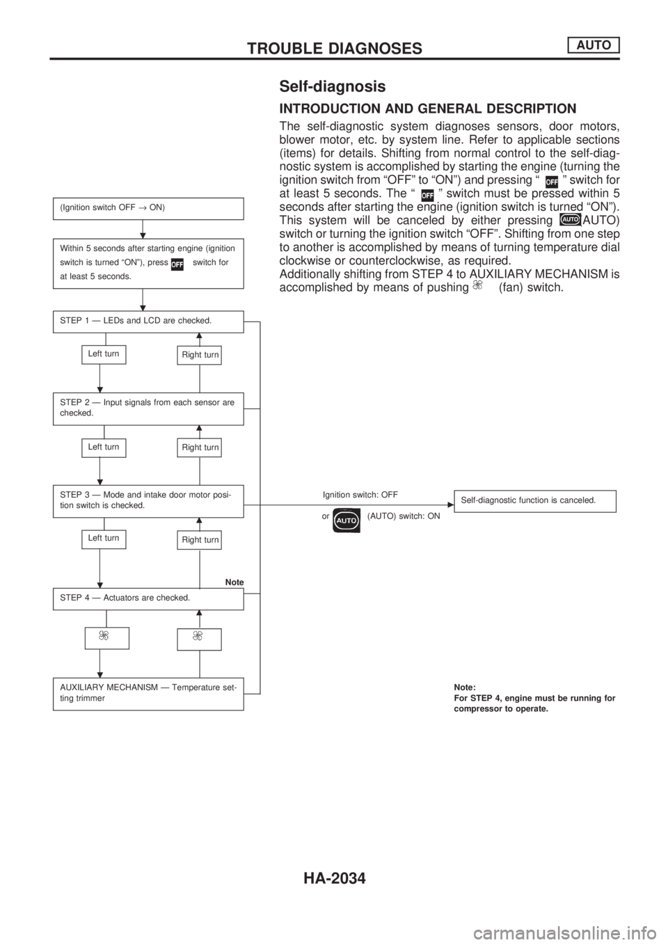
INTRODUCTION AND GENERAL DESCRIPTION
The self-diagnostic system diagnoses sensors, door motors,
blower motor, etc. by system line. Refer to applicable sections
(items) for details. Shifting from normal control to the self-diag-
nostic system is accomplished by starting the engine (turning the
ignition switch from ªOFFº to ªONº) and pressing ª
º switch for
at least 5 seconds. The ª
º switch must be pressed within 5
seconds after starting the engine (ignition switch is turned ªONº).
This system will be canceled by either pressing
(AUTO)
switch or turning the ignition switch ªOFFº. Shifting from one step
to another is accomplished by means of turning temperature dial
clockwise or counterclockwise, as required.
Additionally shifting from STEP 4 to AUXILIARY MECHANISM is
accomplished by means of pushing
(fan) switch.
(Ignition switch OFF®ON)
Within 5 seconds after starting engine (ignition
switch is turned ªONº), press
switch for
at least 5 seconds.
STEP 1 Ð LEDs and LCD are checked.
m
Left turnRight turn
STEP 2 Ð Input signals from each sensor are
checked.
m
Left turnRight turn
STEP 3 Ð Mode and intake door motor posi-
tion switch is checked.Ignition switch: OFFc
or(AUTO) switch: ONSelf-diagnostic function is canceled.m
Left turnRight turn
Note
STEP 4 Ð Actuators are checked.
m
AUXILIARY MECHANISM Ð Temperature set-
ting trimmerNote:
For STEP 4, engine must be running for
compressor to operate.
.
.
.
.
.
.
TROUBLE DIAGNOSESAUTO
HA-2034
Page 536 of 666
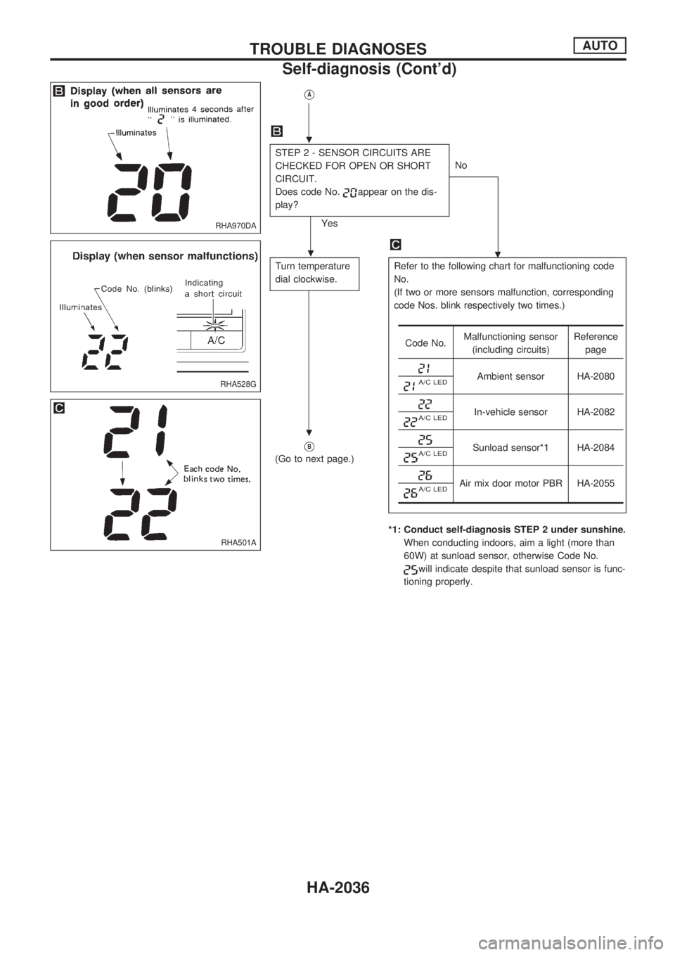
VA
STEP 2 - SENSOR CIRCUITS ARE
CHECKED FOR OPEN OR SHORT
CIRCUIT.
Does code No.
appear on the dis-
play?
YesNo
.
Turn temperature
dial clockwise.Refer to the following chart for malfunctioning code
No.
(If two or more sensors malfunction, corresponding
code Nos. blink respectively two times.)
*1: Conduct self-diagnosis STEP 2 under sunshine.
When conducting indoors, aim a light (more than
60W) at sunload sensor, otherwise Code No.
will indicate despite that sunload sensor is func-
tioning properly.
VB
(Go to next page.)
Code No.Malfunctioning sensor
(including circuits)Reference
page
Ambient sensor HA-2080A/C LED
In-vehicle sensor HA-2082A/C LED
Sunload sensor*1 HA-2084A/C LED
Air mix door motor PBR HA-2055A/C LED
RHA970DA
RHA528G
RHA501A
.
.
.
TROUBLE DIAGNOSESAUTO
Self-diagnosis (Cont'd)
HA-2036
Page 545 of 666
A/C System
TROUBLE DIAGNOSIS PROCEDURE FOR A/C SYSTEM
SYMPTOM:
lA/C system does not come on.
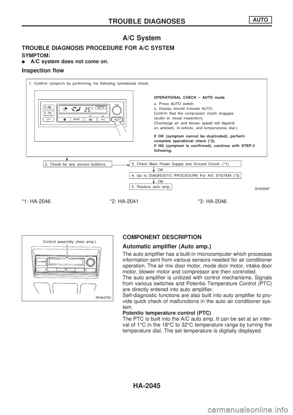
Inspection flow
*1: HA-2046 *2: HA-2041 *3: HA-2046
COMPONENT DESCRIPTION
Automatic amplifier (Auto amp.)
The auto amplifier has a built-in microcomputer which processes
information sent from various sensors needed for air conditioner
operation. The air mix door motor, mode door motor, intake door
motor, blower motor and compressor are then controlled.
The auto amplifier is unitized with control mechanisms. Signals
from various switches and Potentio Temperature Control (PTC)
are directly entered into auto amplifier.
Self-diagnostic functions are also built into auto amplifier to pro-
vide quick check of malfunctions in the auto air conditioner sys-
tem.
Potentio temperature control (PTC)
The PTC is built into the A/C auto amp. It can be set at an inter-
val of 1ÉC in the 18ÉC to 32ÉC temperature range by turning the
temperature dial. The set temperature is digitally displayed.
SHA354F
RHA470H
TROUBLE DIAGNOSESAUTO
HA-2045
Page 548 of 666
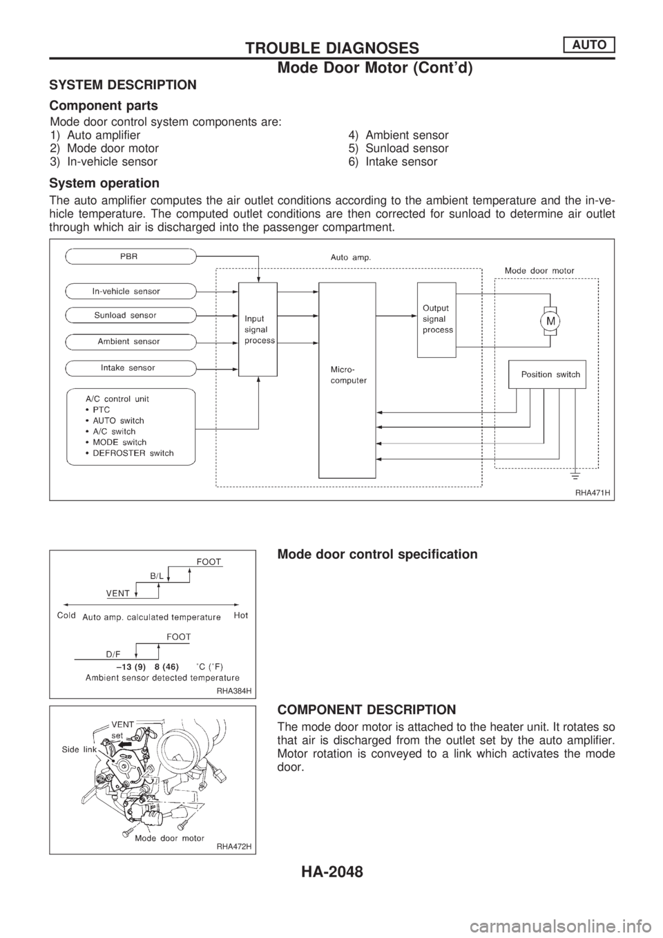
SYSTEM DESCRIPTION
Component parts
Mode door control system components are:
1) Auto amplifier
2) Mode door motor
3) In-vehicle sensor4) Ambient sensor
5) Sunload sensor
6) Intake sensor
System operation
The auto amplifier computes the air outlet conditions according to the ambient temperature and the in-ve-
hicle temperature. The computed outlet conditions are then corrected for sunload to determine air outlet
through which air is discharged into the passenger compartment.
Mode door control specification
COMPONENT DESCRIPTION
The mode door motor is attached to the heater unit. It rotates so
that air is discharged from the outlet set by the auto amplifier.
Motor rotation is conveyed to a link which activates the mode
door.
RHA471H
RHA384H
RHA472H
TROUBLE DIAGNOSESAUTO
Mode Door Motor (Cont'd)
HA-2048
Page 553 of 666
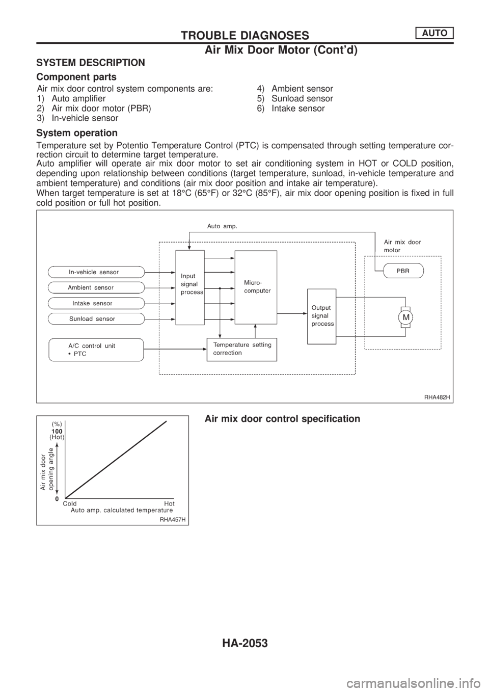
SYSTEM DESCRIPTION
Component parts
Air mix door control system components are:
1) Auto amplifier
2) Air mix door motor (PBR)
3) In-vehicle sensor4) Ambient sensor
5) Sunload sensor
6) Intake sensor
System operation
Temperature set by Potentio Temperature Control (PTC) is compensated through setting temperature cor-
rection circuit to determine target temperature.
Auto amplifier will operate air mix door motor to set air conditioning system in HOT or COLD position,
depending upon relationship between conditions (target temperature, sunload, in-vehicle temperature and
ambient temperature) and conditions (air mix door position and intake air temperature).
When target temperature is set at 18ÉC (65ÉF) or 32ÉC (85ÉF), air mix door opening position is fixed in full
cold position or full hot position.
Air mix door control specification
RHA482H
RHA457H
TROUBLE DIAGNOSESAUTO
Air Mix Door Motor (Cont'd)
HA-2053
Page 559 of 666
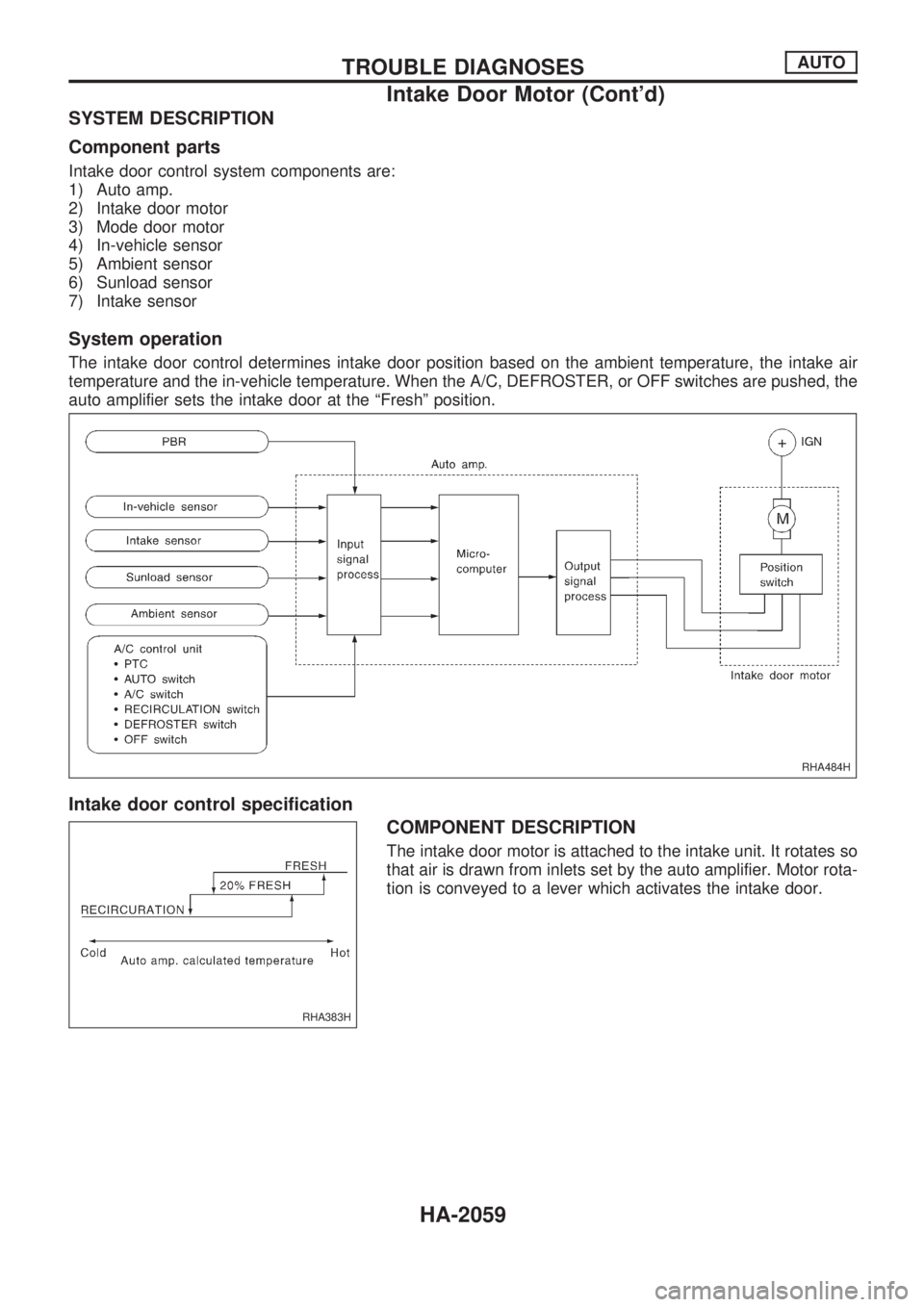
SYSTEM DESCRIPTION
Component parts
Intake door control system components are:
1) Auto amp.
2) Intake door motor
3) Mode door motor
4) In-vehicle sensor
5) Ambient sensor
6) Sunload sensor
7) Intake sensor
System operation
The intake door control determines intake door position based on the ambient temperature, the intake air
temperature and the in-vehicle temperature. When the A/C, DEFROSTER, or OFF switches are pushed, the
auto amplifier sets the intake door at the ªFreshº position.
Intake door control specification
COMPONENT DESCRIPTION
The intake door motor is attached to the intake unit. It rotates so
that air is drawn from inlets set by the auto amplifier. Motor rota-
tion is conveyed to a lever which activates the intake door.
RHA484H
RHA383H
TROUBLE DIAGNOSESAUTO
Intake Door Motor (Cont'd)
HA-2059
Page 563 of 666
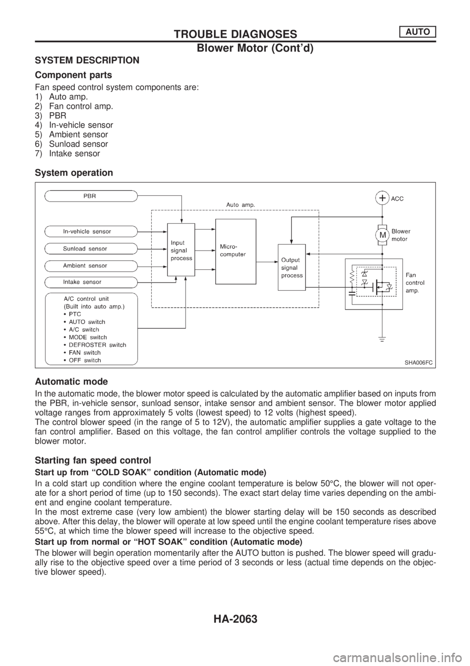
SYSTEM DESCRIPTION
Component parts
Fan speed control system components are:
1) Auto amp.
2) Fan control amp.
3) PBR
4) In-vehicle sensor
5) Ambient sensor
6) Sunload sensor
7) Intake sensor
System operation
Automatic mode
In the automatic mode, the blower motor speed is calculated by the automatic amplifier based on inputs from
the PBR, in-vehicle sensor, sunload sensor, intake sensor and ambient sensor. The blower motor applied
voltage ranges from approximately 5 volts (lowest speed) to 12 volts (highest speed).
The control blower speed (in the range of 5 to 12V), the automatic amplifier supplies a gate voltage to the
fan control amplifier. Based on this voltage, the fan control amplifier controls the voltage supplied to the
blower motor.
Starting fan speed control
Start up from ªCOLD SOAKº condition (Automatic mode)
In a cold start up condition where the engine coolant temperature is below 50ÉC, the blower will not oper-
ate for a short period of time (up to 150 seconds). The exact start delay time varies depending on the ambi-
ent and engine coolant temperature.
In the most extreme case (very low ambient) the blower starting delay will be 150 seconds as described
above. After this delay, the blower will operate at low speed until the engine coolant temperature rises above
55ÉC, at which time the blower speed will increase to the objective speed.
Start up from normal or ªHOT SOAKº condition (Automatic mode)
The blower will begin operation momentarily after the AUTO button is pushed. The blower speed will gradu-
ally rise to the objective speed over a time period of 3 seconds or less (actual time depends on the objec-
tive blower speed).
SHA006FC
TROUBLE DIAGNOSESAUTO
Blower Motor (Cont'd)
HA-2063
Page 569 of 666

SYSTEM DESCRIPTION
Auto amplifier controls compressor operation by ambient tem-
perature and signal from ECM.
Low temperature protection control
Auto amplifier will turn the compressor ªONº or ªOFFº as deter-
mined by a signal detected by ambient sensor.
When ambient temperatures are greater than 1ÉC, the compres-
sor turns ªONº. The compressor turns ªOFFº when ambient tem-
peratures are less than þ2ÉC.
RHA094GA
TROUBLE DIAGNOSESAUTO
Magnet Clutch (Cont'd)
HA-2069
Page 580 of 666
Ambient Sensor
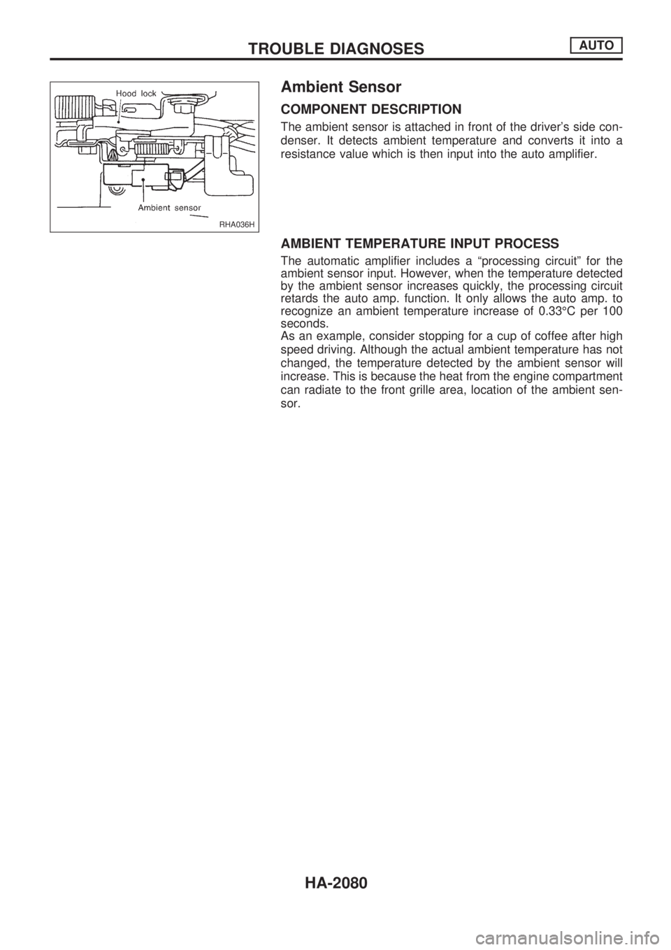
COMPONENT DESCRIPTION
The ambient sensor is attached in front of the driver's side con-
denser. It detects ambient temperature and converts it into a
resistance value which is then input into the auto amplifier.
AMBIENT TEMPERATURE INPUT PROCESS
The automatic amplifier includes a ªprocessing circuitº for the
ambient sensor input. However, when the temperature detected
by the ambient sensor increases quickly, the processing circuit
retards the auto amp. function. It only allows the auto amp. to
recognize an ambient temperature increase of 0.33ÉC per 100
seconds.
As an example, consider stopping for a cup of coffee after high
speed driving. Although the actual ambient temperature has not
changed, the temperature detected by the ambient sensor will
increase. This is because the heat from the engine compartment
can radiate to the front grille area, location of the ambient sen-
sor.
RHA036H
TROUBLE DIAGNOSESAUTO
HA-2080