fuse chart NISSAN PICK-UP 1999 Repair Manual
[x] Cancel search | Manufacturer: NISSAN, Model Year: 1999, Model line: PICK-UP, Model: NISSAN PICK-UP 1999Pages: 666, PDF Size: 16.21 MB
Page 214 of 666

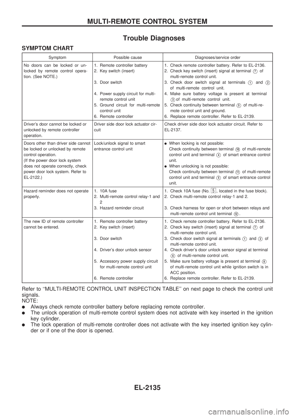
Trouble Diagnoses
SYMPTOM CHART
Symptom Possible cause Diagnoses/service order
No doors can be locked or un-
locked by remote control opera-
tion. (See NOTE.)1. Remote controller battery
2. Key switch (insert)
3. Door switch
4. Power supply circuit for multi-
remote control unit
5. Ground circuit for multi-remote
control unit
6. Remote controller1. Check remote controller battery. Refer to EL-2136.
2. Check key switch (insert) signal at terminal
V7of
multi-remote control unit.
3. Check door switch signal at terminals
V1andV2
of multi-remote control unit.
4. Make sure battery voltage is present at terminal
V3of multi-remote control unit.
5. Check continuity between terminal
V5of multi-re-
mote control unit and ground.
6. Replace remote controller. Refer to EL-2139.
Driver's door cannot be locked or
unlocked by remote controller
operation.Driver side door lock actuator cir-
cuitCheck driver side door lock actuator circuit. Refer to
EL-2137.
Doors other than driver side cannot
be locked or unlocked by remote
control operation.
(If the power door lock system
does not operate correctly, check
power door lock system. Refer to
EL-2122.)Lock/unlock signal to smart
entrance control unit
lWhen locking is not possible:
Check continuity between terminal
V10of multi-remote
control unit and terminal
V4of smart entrance control
unit.
lWhen unlocking is not possible:
Check continuity between terminal
V11of multi-remote
control unit and terminal
V5of smart entrance control
unit.
Hazard reminder does not operate
properly.1. 10A fuse
2. Multi-remote control relay-1 and
2
3. Hazard reminder circuit1. Check 10A fuse (No.
5, located in the fuse block).
2. Check multi-remote control relay-1 and 2.
3. Check harness for open or short between relays and
multi-remote control unit terminal
V12.
The new ID of remote controller
cannot be entered.1. Remote controller battery
2. Key switch (insert)
3. Door switch
4. Driver's door unlock sensor
5. Accessory power supply circuit
for multi-remote control unit
6. Remote controller1. Check remote controller battery. Refer to EL-2136.
2. Check key switch (insert) signal at terminal
V7of
multi-remote control unit.
3. Check door switch signal at terminals
V1andV2of
multi-remote control unit.
4. Check driver's door unlock sensor signal at terminal
V6of multi-remote control unit.
5. Make sure battery voltage is present at terminal
V8
of multi-remote control unit while ignition switch is in
ACC position.
6. Replace remote controller. Refer to EL-2139.
Refer to ``MULTI-REMOTE CONTROL UNIT INSPECTION TABLE'' on next page to check the control unit
signals.
NOTE:
lAlways check remote controller battery before replacing remote controller.
lThe unlock operation of multi-remote control system does not activate with key inserted in the ignition
key cylinder.
lThe lock operation of multi-remote controller does not activate with the key inserted ignition key cylin-
der or if one of the door is opened.
MULTI-REMOTE CONTROL SYSTEM
EL-2135
Page 386 of 666

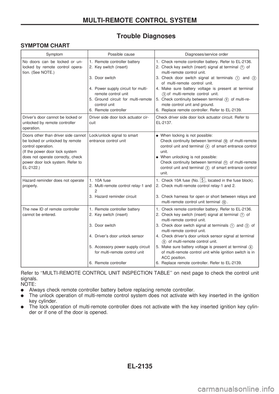
Trouble Diagnoses
SYMPTOM CHART
Symptom Possible cause Diagnoses/service order
No doors can be locked or un-
locked by remote control opera-
tion. (See NOTE.)1. Remote controller battery
2. Key switch (insert)
3. Door switch
4. Power supply circuit for multi-
remote control unit
5. Ground circuit for multi-remote
control unit
6. Remote controller1. Check remote controller battery. Refer to EL-2136.
2. Check key switch (insert) signal at terminal
V7of
multi-remote control unit.
3. Check door switch signal at terminals
V1andV2
of multi-remote control unit.
4. Make sure battery voltage is present at terminal
V3of multi-remote control unit.
5. Check continuity between terminal
V5of multi-re-
mote control unit and ground.
6. Replace remote controller. Refer to EL-2139.
Driver's door cannot be locked or
unlocked by remote controller
operation.Driver side door lock actuator cir-
cuitCheck driver side door lock actuator circuit. Refer to
EL-2137.
Doors other than driver side cannot
be locked or unlocked by remote
control operation.
(If the power door lock system
does not operate correctly, check
power door lock system. Refer to
EL-2122.)Lock/unlock signal to smart
entrance control unit
lWhen locking is not possible:
Check continuity between terminal
V10of multi-remote
control unit and terminal
V4of smart entrance control
unit.
lWhen unlocking is not possible:
Check continuity between terminal
V11of multi-remote
control unit and terminal
V5of smart entrance control
unit.
Hazard reminder does not operate
properly.1. 10A fuse
2. Multi-remote control relay-1 and
2
3. Hazard reminder circuit1. Check 10A fuse (No.
5, located in the fuse block).
2. Check multi-remote control relay-1 and 2.
3. Check harness for open or short between relays and
multi-remote control unit terminal
V12.
The new ID of remote controller
cannot be entered.1. Remote controller battery
2. Key switch (insert)
3. Door switch
4. Driver's door unlock sensor
5. Accessory power supply circuit
for multi-remote control unit
6. Remote controller1. Check remote controller battery. Refer to EL-2136.
2. Check key switch (insert) signal at terminal
V7of
multi-remote control unit.
3. Check door switch signal at terminals
V1andV2of
multi-remote control unit.
4. Check driver's door unlock sensor signal at terminal
V6of multi-remote control unit.
5. Make sure battery voltage is present at terminal
V8
of multi-remote control unit while ignition switch is in
ACC position.
6. Replace remote controller. Refer to EL-2139.
Refer to ``MULTI-REMOTE CONTROL UNIT INSPECTION TABLE'' on next page to check the control unit
signals.
NOTE:
lAlways check remote controller battery before replacing remote controller.
lThe unlock operation of multi-remote control system does not activate with key inserted in the ignition
key cylinder.
lThe lock operation of multi-remote controller does not activate with the key inserted ignition key cylin-
der or if one of the door is opened.
MULTI-REMOTE CONTROL SYSTEM
EL-2135
Page 647 of 666

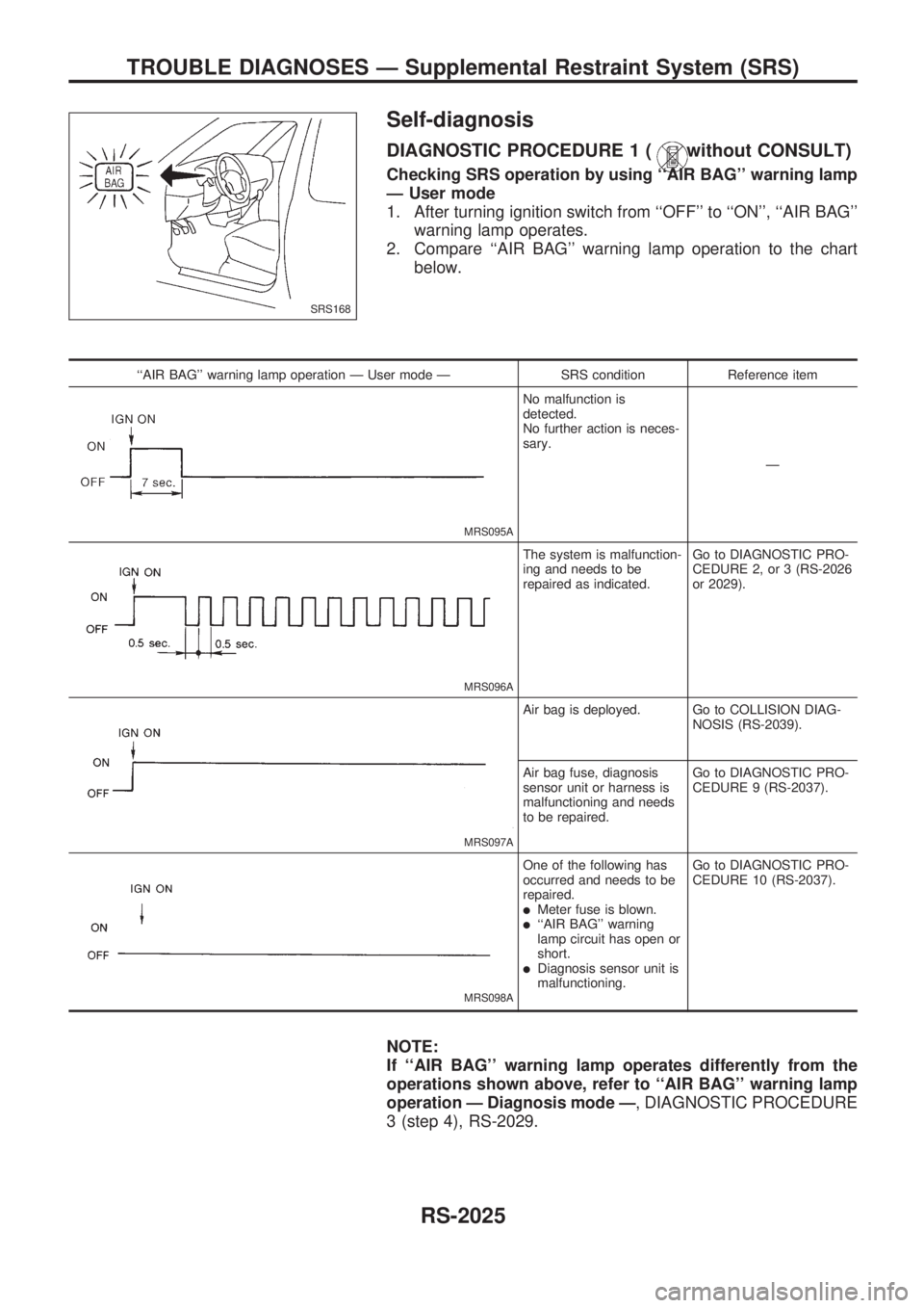
Self-diagnosis
DIAGNOSTIC PROCEDURE 1 (without CONSULT)
Checking SRS operation by using ``AIR BAG'' warning lamp
Ð User mode
1. After turning ignition switch from ``OFF'' to ``ON'', ``AIR BAG''
warning lamp operates.
2. Compare ``AIR BAG'' warning lamp operation to the chart
below.
``AIR BAG'' warning lamp operation Ð User mode Ð SRS condition Reference item
MRS095A
No malfunction is
detected.
No further action is neces-
sary.
Ð
MRS096A
The system is malfunction-
ing and needs to be
repaired as indicated.Go to DIAGNOSTIC PRO-
CEDURE 2, or 3 (RS-2026
or 2029).
MRS097A
Air bag is deployed. Go to COLLISION DIAG-
NOSIS (RS-2039).
Air bag fuse, diagnosis
sensor unit or harness is
malfunctioning and needs
to be repaired.Go to DIAGNOSTIC PRO-
CEDURE 9 (RS-2037).
MRS098A
One of the following has
occurred and needs to be
repaired.
lMeter fuse is blown.l``AIR BAG'' warning
lamp circuit has open or
short.
lDiagnosis sensor unit is
malfunctioning.Go to DIAGNOSTIC PRO-
CEDURE 10 (RS-2037).
NOTE:
If ``AIR BAG'' warning lamp operates differently from the
operations shown above, refer to ``AIR BAG'' warning lamp
operation Ð Diagnosis mode Ð, DIAGNOSTIC PROCEDURE
3 (step 4), RS-2029.
SRS168
TROUBLE DIAGNOSES Ð Supplemental Restraint System (SRS)
RS-2025
Page 655 of 666

NOTE:
When diagnosis sensor unit is replaced with new one, ``AIR
BAG'' warning lamp will operate in User mode. Checking
``AIR BAG'' warning lamp operation in Diagnosis mode is
not required. Go to step 6.
5. If ``AIR BAG'' warning lamp operates as shown in No. 1 in
chart above, turn ignition switch ``OFF'' to reset from Diag-
nosis mode to User mode and to erase the memory of the
malfunction. Then go to step 6.
If ``AIR BAG'' warning lamp operates as shown in No. 2 in
chart above, the malfunctioning part is not repaired
completely, or another malfunctioning part is detected. Go to
DIAGNOSTIC PROCEDURE 3, page RS-2029, and repair
malfunctioning part completely.
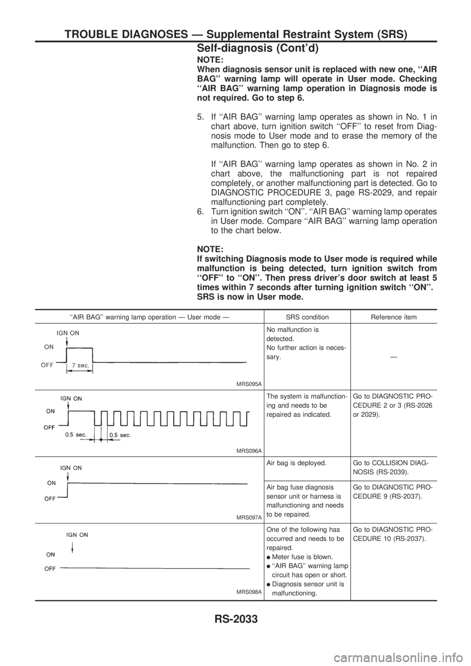
6. Turn ignition switch ``ON''. ``AIR BAG'' warning lamp operates
in User mode. Compare ``AIR BAG'' warning lamp operation
to the chart below.
NOTE:
If switching Diagnosis mode to User mode is required while
malfunction is being detected, turn ignition switch from
``OFF'' to ``ON''. Then press driver's door switch at least 5
times within 7 seconds after turning ignition switch ``ON''.
SRS is now in User mode.
``AIR BAG'' warning lamp operation Ð User mode Ð SRS condition Reference item
MRS095A
No malfunction is
detected.
No further action is neces-
sary.Ð
MRS096A
The system is malfunction-
ing and needs to be
repaired as indicated.Go to DIAGNOSTIC PRO-
CEDURE 2 or 3 (RS-2026
or 2029).
MRS097A
Air bag is deployed. Go to COLLISION DIAG-
NOSIS (RS-2039).
Air bag fuse diagnosis
sensor unit or harness is
malfunctioning and needs
to be repaired.Go to DIAGNOSTIC PRO-
CEDURE 9 (RS-2037).
MRS098A
One of the following has
occurred and needs to be
repaired.
lMeter fuse is blown.
l``AIR BAG'' warning lamp
circuit has open or short.
lDiagnosis sensor unit is
malfunctioning.Go to DIAGNOSTIC PRO-
CEDURE 10 (RS-2037).
TROUBLE DIAGNOSES Ð Supplemental Restraint System (SRS)
Self-diagnosis (Cont'd)
RS-2033