NISSAN PICK-UP 2001 Repair Manual
Manufacturer: NISSAN, Model Year: 2001, Model line: PICK-UP, Model: NISSAN PICK-UP 2001Pages: 1306, PDF Size: 31.7 MB
Page 121 of 1306
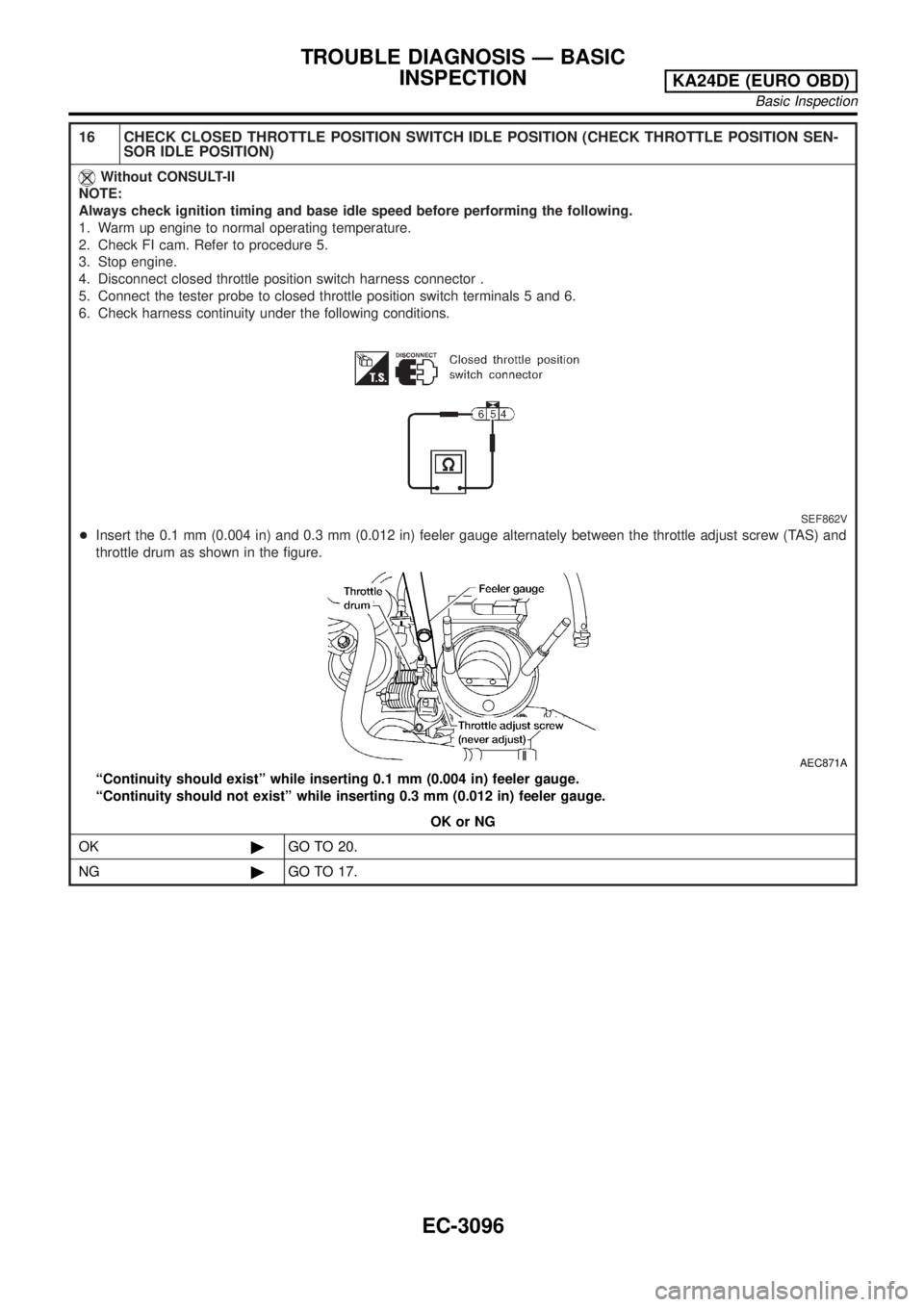
16 CHECK CLOSED THROTTLE POSITION SWITCH IDLE POSITION (CHECK THROTTLE POSITION SEN-
SOR IDLE POSITION)
Without CONSULT-II
NOTE:
Always check ignition timing and base idle speed before performing the following.
1. Warm up engine to normal operating temperature.
2. Check FI cam. Refer to procedure 5.
3. Stop engine.
4. Disconnect closed throttle position switch harness connector .
5. Connect the tester probe to closed throttle position switch terminals 5 and 6.
6. Check harness continuity under the following conditions.
SEF862V
+Insert the 0.1 mm (0.004 in) and 0.3 mm (0.012 in) feeler gauge alternately between the throttle adjust screw (TAS) and
throttle drum as shown in the figure.
AEC871A
ªContinuity should existº while inserting 0.1 mm (0.004 in) feeler gauge.
ªContinuity should not existº while inserting 0.3 mm (0.012 in) feeler gauge.
OK or NG
OK©GO TO 20.
NG©GO TO 17.
TROUBLE DIAGNOSIS Ð BASIC
INSPECTION
KA24DE (EURO OBD)
Basic Inspection
EC-3096
Page 122 of 1306
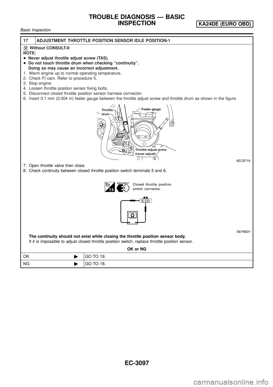
17 ADJUSTMENT THROTTLE POSITION SENSOR IDLE POSITION-1
Without CONSULT-II
NOTE:
+Never adjust throttle adjust screw (TAS).
+Do not touch throttle drum when checking ªcontinuityº.
Doing so may cause an incorrect adjustment.
1. Warm engine up to normal operating temperature.
2. Check FI cam. Refer to procedure 5.
3. Stop engine.
4. Loosen throttle position sensor fixing bolts.
5. Disconnect closed throttle position sensor harness connector.
6. Insert 0.1 mm (0.004 in) feeler gauge between the throttle adjust screw and throttle drum as shown in the figure.
AEC871A
7. Open throttle valve then close.
8. Check continuity between closed throttle position switch terminals 5 and 6.
SEF862V
The continuity should not exist while closing the throttle position sensor body.
If it is impossible to adjust closed throttle position switch, replace throttle position sensor.
OK or NG
OK©GO TO 19.
NG©GO TO 18.
TROUBLE DIAGNOSIS Ð BASIC
INSPECTION
KA24DE (EURO OBD)
Basic Inspection
EC-3097
Page 123 of 1306

18 ADJUSTMENT THROTTLE POSITION SENSOR IDLE POSITION-2
Without CONSULT-II
Turn throttle position sensor body counterclockwise until continuity does not exist.
AEC872A
©GO TO 19.
19 ADJUSTMENT THROTTLE POSITION SENSOR IDLE POSITION-3
Without CONSULT-II
1. Temporarily tighten sensor body fixing bolts as follows.
+Gradually move the sensor body clockwise and stop it when the continuity comes to exist, then tighten sensor
body fixing bolts.
AEC872A
2. Make sure two or three times that the continuity exists when the throttle valve is closed and continuity does not exist
when it is opened.
3. Remove 0.1 mm (0.004 in) feeler gauge then insert 0.3 mm (0.012 in) feeler gauge.
4. Make sure two or three times that continuity does not exist when the throttle valve is closed.
5. Tighten throttle position sensor.
6. Check the continuity again.
Continuity does not exist while closing the throttle valve.
OK or NG
OK©GO TO 20.
NG©GO TO 17.
20 REINSTALLATION
Without CONSULT-II
1. Remove 0.3 mm (0.012 in) feeler gauge.
2. Reconnect throttle position sensor harness connector and closed throttle position switch harness connector.
3. Rev engine (2,000 to 3,000 rpm) two or three times under no-load and then run engine at idle speed.
©GO TO 21.
TROUBLE DIAGNOSIS Ð BASIC
INSPECTION
KA24DE (EURO OBD)
Basic Inspection
EC-3098
Page 124 of 1306
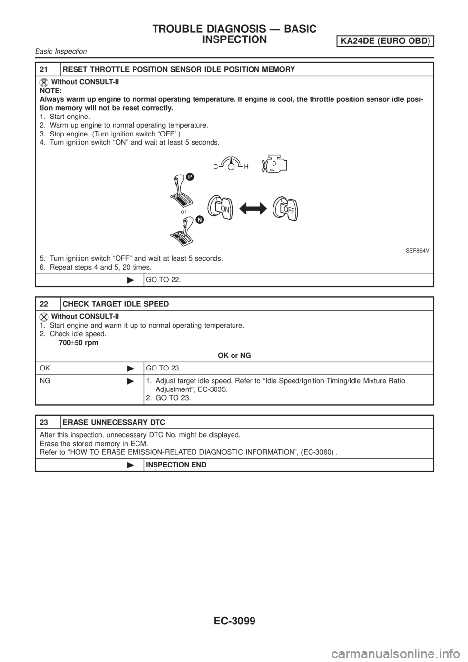
21 RESET THROTTLE POSITION SENSOR IDLE POSITION MEMORY
Without CONSULT-II
NOTE:
Always warm up engine to normal operating temperature. If engine is cool, the throttle position sensor idle posi-
tion memory will not be reset correctly.
1. Start engine.
2. Warm up engine to normal operating temperature.
3. Stop engine. (Turn ignition switch ªOFFº.)
4. Turn ignition switch ªONº and wait at least 5 seconds.
SEF864V
5. Turn ignition switch ªOFFº and wait at least 5 seconds.
6. Repeat steps 4 and 5, 20 times.
©GO TO 22.
22 CHECK TARGET IDLE SPEED
Without CONSULT-II
1. Start engine and warm it up to normal operating temperature.
2. Check idle speed.
700±50 rpm
OK or NG
OK©GO TO 23.
NG©1. Adjust target idle speed. Refer to ªIdle Speed/Ignition Timing/Idle Mixture Ratio
Adjustmentº, EC-3035.
2. GO TO 23.
23 ERASE UNNECESSARY DTC
After this inspection, unnecessary DTC No. might be displayed.
Erase the stored memory in ECM.
Refer to ªHOW TO ERASE EMISSION-RELATED DIAGNOSTIC INFORMATIONº, (EC-3060) .
©INSPECTION END
TROUBLE DIAGNOSIS Ð BASIC
INSPECTION
KA24DE (EURO OBD)
Basic Inspection
EC-3099
Page 125 of 1306
DTC Inspection Priority ChartNEEC0039If some DTCs are displayed at the same time, perform inspections one by one based on the following prior-
ity chart.
Priority Detected items (DTC)
1+P0101, P0102, P0103 MAF sensor
+P0112, P0113, P0127 IAT sensor
+P0117, P0118 ECT sensor
+P0121, P0122, P0123 TP sensor
+P0327, P0328 KS
+P0340 CMP sensor
+P0500 VSS
+P0605 ECM
+P1706 PNP switch
2+P0031, P0032 HO2S1 heater
+P0037, P0038 HO2S2 heater
+P0132, P0133, P0134, P1143, P1144 HO2S1
+P0138, P0139, P1146, P1147 HO2S2
P0335, P1336 CKP sensor
+P0444, P0445 EVAP canister purge volume control solenoid valve
+P0510 CTP switch
3+P0171, P0172 Fuel injection system function
+P0300 - P0304 Misfire
+P0505 ISC system
+P0420 Three way catalyst function
TROUBLE DIAGNOSIS Ð GENERAL
DESCRIPTION
KA24DE (EURO OBD)
DTC Inspection Priority Chart
EC-3100
Page 126 of 1306
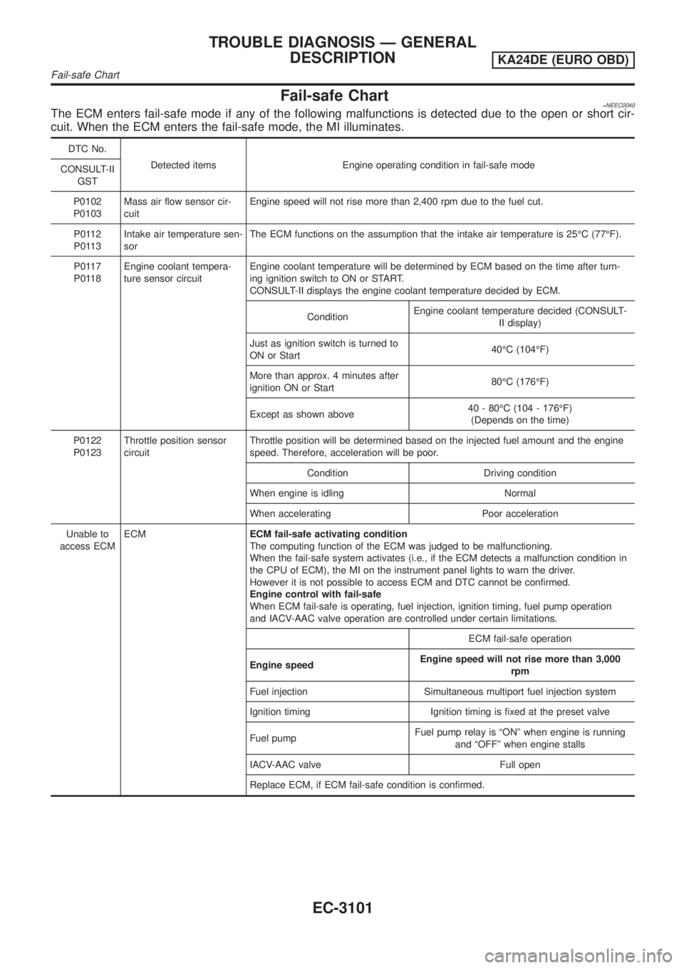
Fail-safe Chart=NEEC0040The ECM enters fail-safe mode if any of the following malfunctions is detected due to the open or short cir-
cuit. When the ECM enters the fail-safe mode, the MI illuminates.
DTC No.
Detected items Engine operating condition in fail-safe mode
CONSULT-II
GST
P0102
P0103Mass air flow sensor cir-
cuitEngine speed will not rise more than 2,400 rpm due to the fuel cut.
P0112
P0113Intake air temperature sen-
sorThe ECM functions on the assumption that the intake air temperature is 25ÉC (77ÉF).
P0117
P0118Engine coolant tempera-
ture sensor circuitEngine coolant temperature will be determined by ECM based on the time after turn-
ing ignition switch to ON or START.
CONSULT-II displays the engine coolant temperature decided by ECM.
ConditionEngine coolant temperature decided (CONSULT-
II display)
Just as ignition switch is turned to
ON or Start40ÉC (104ÉF)
More than approx. 4 minutes after
ignition ON or Start80ÉC (176ÉF)
Except as shown above40 - 80ÉC (104 - 176ÉF)
(Depends on the time)
P0122
P0123Throttle position sensor
circuitThrottle position will be determined based on the injected fuel amount and the engine
speed. Therefore, acceleration will be poor.
Condition Driving condition
When engine is idling Normal
When accelerating Poor acceleration
Unable to
access ECMECMECM fail-safe activating condition
The computing function of the ECM was judged to be malfunctioning.
When the fail-safe system activates (i.e., if the ECM detects a malfunction condition in
the CPU of ECM), the MI on the instrument panel lights to warn the driver.
However it is not possible to access ECM and DTC cannot be confirmed.
Engine control with fail-safe
When ECM fail-safe is operating, fuel injection, ignition timing, fuel pump operation
and IACV-AAC valve operation are controlled under certain limitations.
ECM fail-safe operation
Engine speedEngine speed will not rise more than 3,000
rpm
Fuel injection Simultaneous multiport fuel injection system
Ignition timing Ignition timing is fixed at the preset valve
Fuel pumpFuel pump relay is ªONº when engine is running
and ªOFFº when engine stalls
IACV-AAC valve Full open
Replace ECM, if ECM fail-safe condition is confirmed.
TROUBLE DIAGNOSIS Ð GENERAL
DESCRIPTION
KA24DE (EURO OBD)
Fail-safe Chart
EC-3101
Page 127 of 1306
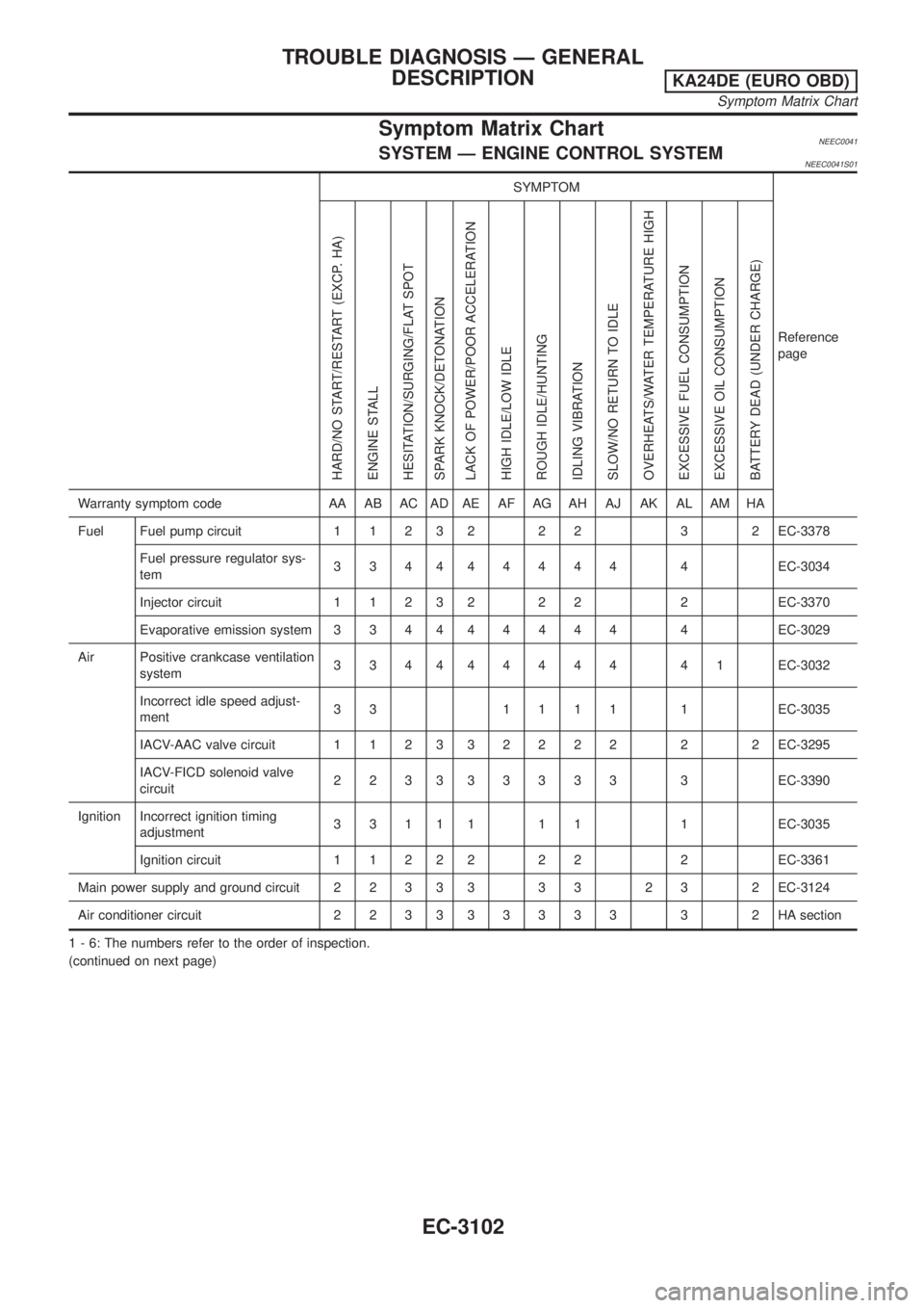
Symptom Matrix ChartNEEC0041SYSTEM Ð ENGINE CONTROL SYSTEMNEEC0041S01
SYMPTOM
Reference
page
HARD/NO START/RESTART (EXCP. HA)
ENGINE STALL
HESITATION/SURGING/FLAT SPOT
SPARK KNOCK/DETONATION
LACK OF POWER/POOR ACCELERATION
HIGH IDLE/LOW IDLE
ROUGH IDLE/HUNTING
IDLING VIBRATION
SLOW/NO RETURN TO IDLE
OVERHEATS/WATER TEMPERATURE HIGH
EXCESSIVE FUEL CONSUMPTION
EXCESSIVE OIL CONSUMPTION
BATTERY DEAD (UNDER CHARGE)
Warranty symptom code AA AB AC AD AE AF AG AH AJ AK AL AM HA
Fuel Fuel pump circuit 1 1 2 3 2 2 2 3 2 EC-3378
Fuel pressure regulator sys-
tem334444444 4EC-3034
Injector circuit 1 1 2 3 2 2 2 2 EC-3370
Evaporative emission system 3 3 4 444444 4EC-3029
Air Positive crankcase ventilation
system334444444 41EC-3032
Incorrect idle speed adjust-
ment33 1111 1EC-3035
IACV-AAC valve circuit 1 1 2 332222 2 2EC-3295
IACV-FICD solenoid valve
circuit223333333 3EC-3390
Ignition Incorrect ignition timing
adjustment3 3 1 1 1 1 1 1 EC-3035
Ignition circuit 1 1 2 2 2 2 2 2 EC-3361
Main power supply and ground circuit 2 2 3 3 3 3 3 2 3 2 EC-3124
Air conditioner circuit 2 2 3 333333 3 2HAsection
1 - 6: The numbers refer to the order of inspection.
(continued on next page)
TROUBLE DIAGNOSIS Ð GENERAL
DESCRIPTION
KA24DE (EURO OBD)
Symptom Matrix Chart
EC-3102
Page 128 of 1306
SYMPTOM
Reference
page
HARD/NO START/RESTART (EXCP. HA)
ENGINE STALL
HESITATION/SURGING/FLAT SPOT
SPARK KNOCK/DETONATION
LACK OF POWER/POOR ACCELERATION
HIGH IDLE/LOW IDLE
ROUGH IDLE/HUNTING
IDLING VIBRATION
SLOW/NO RETURN TO IDLE
OVERHEATS/WATER TEMPERATURE HIGH
EXCESSIVE FUEL CONSUMPTION
EXCESSIVE OIL CONSUMPTION
BATTERY DEAD (UNDER CHARGE)
Warranty symptom code AA AB AC AD AE AF AG AH AJ AK AL AM HA
Camshaft position sensor circuit22333 33 3EC-3270
Mass air flow sensor circuit11222 22 2EC-3143,
EC-3151
Heated oxygen sensor 1 circuit1232 22 2EC-3213,
3310
Engine coolant temperature sen-
sor circuit112323223 2EC-3165
Throttle position sensor circuit 1 222222 2EC-3170
Incorrect throttle position sensor
adjustment31 11111 1EC-3086
Vehicle speed sensor circuit 2 3 3 3 EC-3290
Knock sensor circuit 2 3 EC-3260
ECM 22333333333EC-3308,
3101
Start signal circuit 2EC-3375
PNP switch circuit 3 3 3 3 3 EC-3355
Power steering oil pressure switch
circuit2 3 3 EC-3386
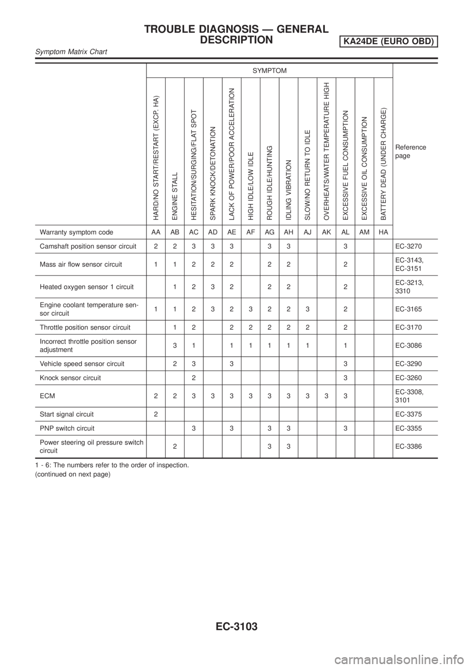
1 - 6: The numbers refer to the order of inspection.
(continued on next page)
TROUBLE DIAGNOSIS Ð GENERAL
DESCRIPTION
KA24DE (EURO OBD)
Symptom Matrix Chart
EC-3103
Page 129 of 1306
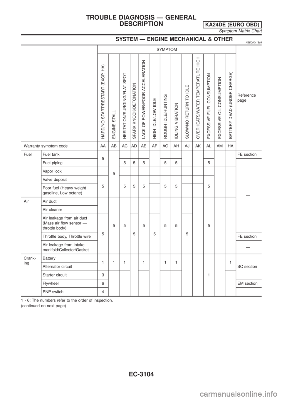
SYSTEM Ð ENGINE MECHANICAL & OTHERNEEC0041S03
SYMPTOM
Reference
page
HARD/NO START/RESTART (EXCP. HA)
ENGINE STALL
HESITATION/SURGING/FLAT SPOT
SPARK KNOCK/DETONATION
LACK OF POWER/POOR ACCELERATION
HIGH IDLE/LOW IDLE
ROUGH IDLE/HUNTING
IDLING VIBRATION
SLOW/NO RETURN TO IDLE
OVERHEATS/WATER TEMPERATURE HIGH
EXCESSIVE FUEL CONSUMPTION
EXCESSIVE OIL CONSUMPTION
BATTERY DEAD (UNDER CHARGE)
Warranty symptom code AA AB AC AD AE AF AG AH AJ AK AL AM HA
Fuel Fuel tank
5
5FE section
Fuel piping 5 5 5 5 5 5
Ð Vapor lock
Valve deposit
555555 5
Poor fuel (Heavy weight
gasoline, Low octane)
Air Air duct
55 5 55 5 Air cleaner
Air leakage from air duct
(Mass air flow sensor Ð
throttle body)
555 5
Throttle body, Throttle wireFE section
Air leakage from intake
manifold/Collector/GasketÐ
Crank-
ingBattery
111 1 11
11
SC section Alternator circuit
Starter circuit 3
Flywheel 6EM section
PNP switch 4Ð
1 - 6: The numbers refer to the order of inspection.
(continued on next page)
TROUBLE DIAGNOSIS Ð GENERAL
DESCRIPTION
KA24DE (EURO OBD)
Symptom Matrix Chart
EC-3104
Page 130 of 1306
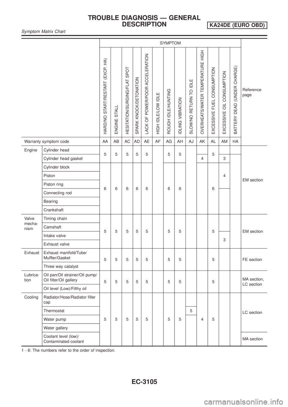
SYMPTOM
Reference
page
HARD/NO START/RESTART (EXCP. HA)
ENGINE STALL
HESITATION/SURGING/FLAT SPOT
SPARK KNOCK/DETONATION
LACK OF POWER/POOR ACCELERATION
HIGH IDLE/LOW IDLE
ROUGH IDLE/HUNTING
IDLING VIBRATION
SLOW/NO RETURN TO IDLE
OVERHEATS/WATER TEMPERATURE HIGH
EXCESSIVE FUEL CONSUMPTION
EXCESSIVE OIL CONSUMPTION
BATTERY DEAD (UNDER CHARGE)
Warranty symptom code AA AB AC AD AE AF AG AH AJ AK AL AM HA
Engine Cylinder head
55555 55 5
EM section Cylinder head gasket 4 3
Cylinder block
66666 66 64 Piston
Piston ring
Connecting rod
Bearing
Crankshaft
Valve
mecha-
nismTiming chain
5 5 5 5 5 5 5 5 EM section Camshaft
Intake valve
3
Exhaust valve
Exhaust Exhaust manifold/Tube/
Muffler/Gasket
5 5 5 5 5 5 5 5 FE section
Three way catalyst
Lubrica-
tionOil pan/Oil strainer/Oil pump/
Oil filter/Oil gallery
55555 55 5MA section,
LC section
Oil level (Low)/Filthy oil
Cooling Radiator/Hose/Radiator filler
cap
55555 55 45LC section Thermostat 5
Water pump
Water gallery
Coolant level (low)/
Contaminated coolantMA section
1 - 6: The numbers refer to the order of inspection.
TROUBLE DIAGNOSIS Ð GENERAL
DESCRIPTION
KA24DE (EURO OBD)
Symptom Matrix Chart
EC-3105