fuel NISSAN PICK-UP 2001 Repair Manual
[x] Cancel search | Manufacturer: NISSAN, Model Year: 2001, Model line: PICK-UP, Model: NISSAN PICK-UP 2001Pages: 1306, PDF Size: 31.7 MB
Page 1 of 1306
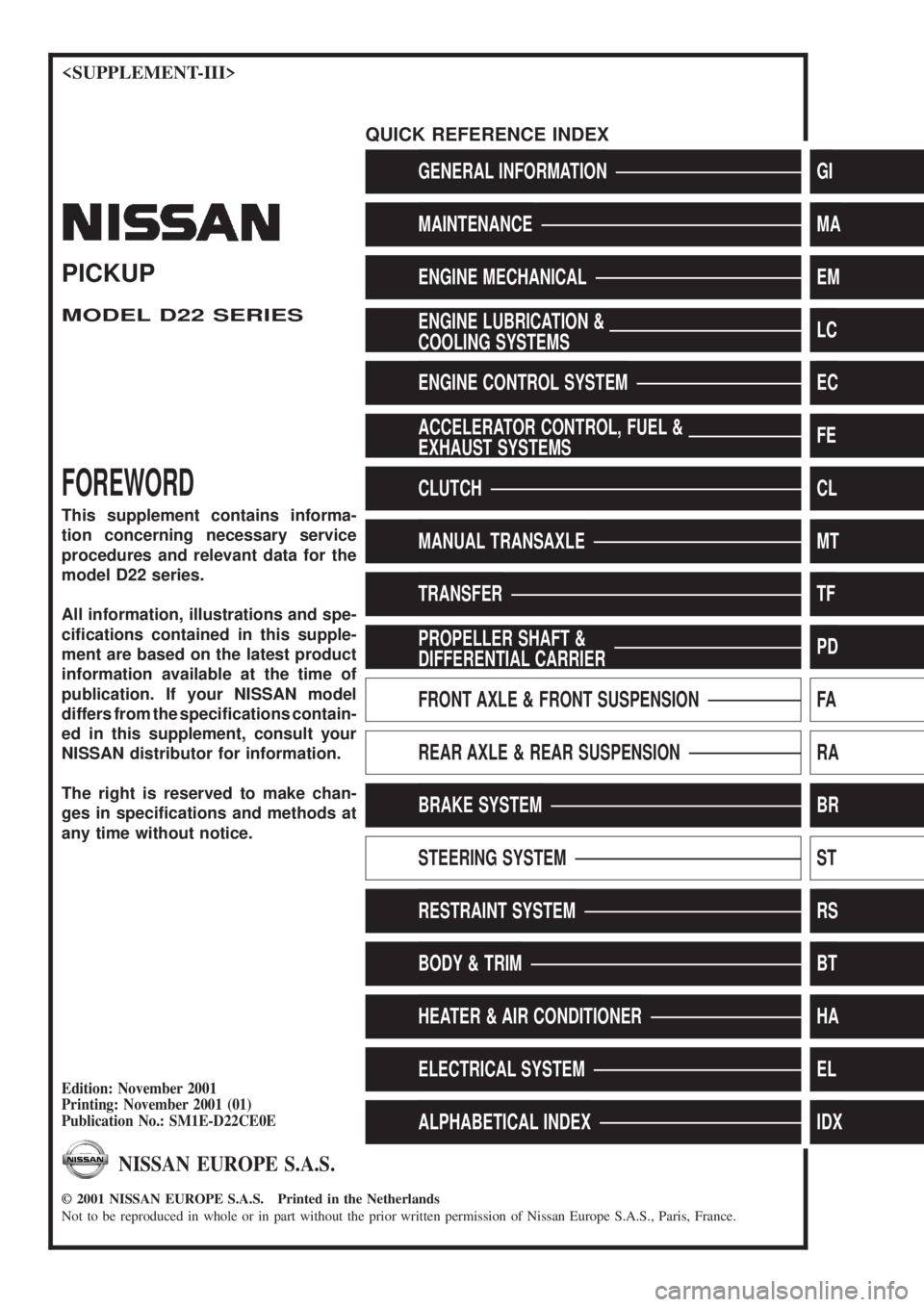
GENERAL INFORMATIONGI
MAINTENANCEMA
ENGINE MECHANICALEM
ENGINE LUBRICATION &
COOLING SYSTEMSLC
ENGINE CONTROL SYSTEMEC
ACCELERATOR CONTROL, FUEL &
EXHAUST SYSTEMSFE
CLUTCHCL
MANUAL TRANSAXLEMT
TRANSFERTF
PROPELLER SHAFT &
DIFFERENTIAL CARRIERPD
FRONT AXLE & FRONT SUSPENSIONFA
REAR AXLE & REAR SUSPENSIONRA
BRAKE SYSTEMBR
STEERING SYSTEMST
RESTRAINT SYSTEMRS
BODY & TRIMBT
HEATER & AIR CONDITIONERHA
ELECTRICAL SYSTEMEL
ALPHABETICAL INDEXIDX
PICKUP
MODEL D22 SERIES
FOREWORD
This supplement contains informa-
tion concerning necessary service
procedures and relevant data for the
model D22 series.
All information, illustrations and spe-
ci®cations contained in this supple-
ment are based on the latest product
information available at the time of
publication. If your NISSAN model
differs from the speci®cations contain-
ed in this supplement, consult your
NISSAN distributor for information.
The right is reserved to make chan-
ges in speci®cations and methods at
any time without notice.
Edition: November 2001
Printing: November 2001 (01)
Publication No.: SM1E-D22CE0E
NISSAN EUROPE S.A.S.
2001 NISSAN EUROPE S.A.S. Printed in the Netherlands
Not to be reproduced in whole or in part without the prior written permission of Nissan Europe S.A.S., Paris, France.
QUICK REFERENCE INDEX
Page 26 of 1306
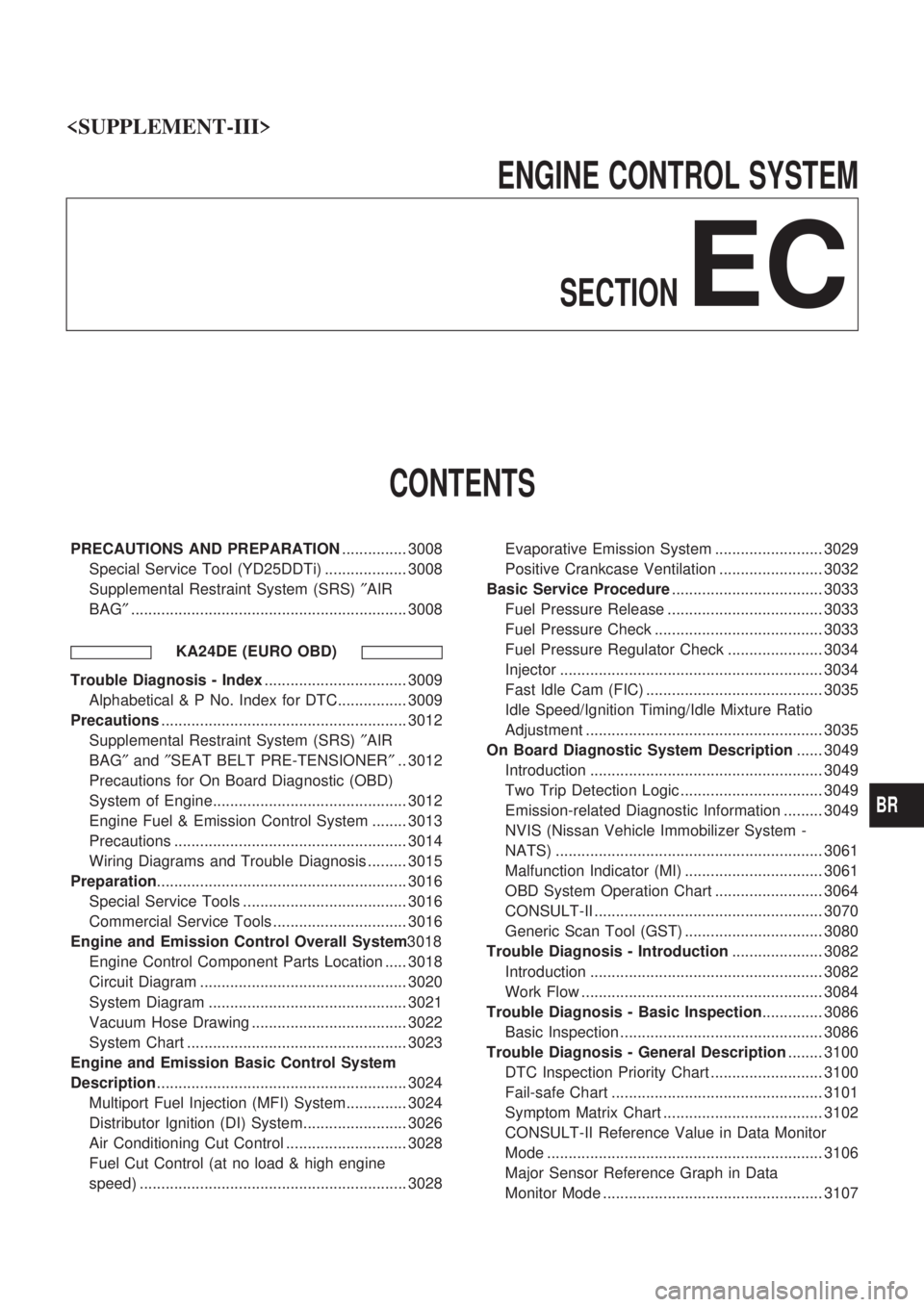
ENGINE CONTROL SYSTEM
SECTION
EC
CONTENTS
PRECAUTIONS AND PREPARATION............... 3008
Special Service Tool (YD25DDTi) ................... 3008
Supplemental Restraint System (SRS)²AIR
BAG²................................................................ 3008
KA24DE (EURO OBD)
Trouble Diagnosis - Index................................. 3009
Alphabetical & P No. Index for DTC................ 3009
Precautions......................................................... 3012
Supplemental Restraint System (SRS)²AIR
BAG²and²SEAT BELT PRE-TENSIONER².. 3012
Precautions for On Board Diagnostic (OBD)
System of Engine............................................. 3012
Engine Fuel & Emission Control System ........ 3013
Precautions ...................................................... 3014
Wiring Diagrams and Trouble Diagnosis ......... 3015
Preparation.......................................................... 3016
Special Service Tools ...................................... 3016
Commercial Service Tools ............................... 3016
Engine and Emission Control Overall System3018
Engine Control Component Parts Location ..... 3018
Circuit Diagram ................................................ 3020
System Diagram .............................................. 3021
Vacuum Hose Drawing .................................... 3022
System Chart ................................................... 3023
Engine and Emission Basic Control System
Description.......................................................... 3024
Multiport Fuel Injection (MFI) System.............. 3024
Distributor Ignition (DI) System........................ 3026
Air Conditioning Cut Control ............................ 3028
Fuel Cut Control (at no load & high engine
speed) .............................................................. 3028Evaporative Emission System ......................... 3029
Positive Crankcase Ventilation ........................ 3032
Basic Service Procedure................................... 3033
Fuel Pressure Release .................................... 3033
Fuel Pressure Check ....................................... 3033
Fuel Pressure Regulator Check ...................... 3034
Injector ............................................................. 3034
Fast Idle Cam (FIC) ......................................... 3035
Idle Speed/Ignition Timing/Idle Mixture Ratio
Adjustment ....................................................... 3035
On Board Diagnostic System Description...... 3049
Introduction ...................................................... 3049
Two Trip Detection Logic ................................. 3049
Emission-related Diagnostic Information ......... 3049
NVIS (Nissan Vehicle Immobilizer System -
NATS) .............................................................. 3061
Malfunction Indicator (MI) ................................ 3061
OBD System Operation Chart ......................... 3064
CONSULT-II ..................................................... 3070
Generic Scan Tool (GST) ................................ 3080
Trouble Diagnosis - Introduction..................... 3082
Introduction ...................................................... 3082
Work Flow ........................................................ 3084
Trouble Diagnosis - Basic Inspection.............. 3086
Basic Inspection ............................................... 3086
Trouble Diagnosis - General Description........ 3100
DTC Inspection Priority Chart .......................... 3100
Fail-safe Chart ................................................. 3101
Symptom Matrix Chart ..................................... 3102
CONSULT-II Reference Value in Data Monitor
Mode ................................................................ 3106
Major Sensor Reference Graph in Data
Monitor Mode ................................................... 3107
BR
Page 28 of 1306
Component Description ................................... 3213
CONSULT-II Reference Value in Data Monitor
Mode ................................................................ 3213
ECM Terminals and Reference Value ............. 3213
On Board Diagnosis Logic ............................... 3214
DTC Confirmation Procedure .......................... 3214
Overall Function Check ................................... 3215
Wiring Diagram ................................................ 3216
Diagnostic Procedure....................................... 3217
DTC P0138 HO2S2.............................................. 3220
Component Description ................................... 3220
CONSULT-II Reference Value in Data Monitor
Mode ................................................................ 3220
ECM Terminals and Reference Value ............. 3220
On Board Diagnosis Logic ............................... 3220
DTC Confirmation Procedure .......................... 3221
Overall Function Check ................................... 3221
Wiring Diagram ................................................ 3222
Diagnostic Procedure....................................... 3223
DTC P0139 HO2S2.............................................. 3227
Component Description ................................... 3227
CONSULT-II Reference Value in Data Monitor
Mode ................................................................ 3227
ECM Terminals and Reference Value ............. 3227
On Board Diagnosis Logic ............................... 3227
DTC Confirmation Procedure .......................... 3228
Overall Function Check ................................... 3229
Wiring Diagram ................................................ 3230
Diagnostic Procedure....................................... 3231
DTC P0171 Fuel Injection System Function.... 3237
On Board Diagnosis Logic ............................... 3237
DTC Confirmation Procedure .......................... 3237
Wiring Diagram ................................................ 3239
Diagnostic Procedure....................................... 3240
DTC P0172 Fuel Injection System Function.... 3244
On Board Diagnosis Logic ............................... 3244
DTC Confirmation Procedure .......................... 3244
Wiring Diagram ................................................ 3246
Diagnostic Procedure....................................... 3247
DTC P0300 - P0304 No.4-1Cylinder Misfire,
Multiple Cylinder Misfire.................................... 3251
On Board Diagnosis Logic ............................... 3251
DTC Confirmation Procedure .......................... 3251
Diagnostic Procedure....................................... 3252
DTC P0327, P0328 KS........................................ 3260
Component Description ................................... 3260
ECM Terminals and Reference Value ............. 3260
On Board Diagnosis Logic ............................... 3260
DTC Confirmation Procedure .......................... 3260
Wiring Diagram ................................................ 3261
Diagnostic Procedure....................................... 3262
DTC P0335 CKP Sensor (OBD)......................... 3264
Component Description ................................... 3264
ECM Terminals and Reference Value ............. 3264On Board Diagnosis Logic ............................... 3264
DTC Confirmation Procedure .......................... 3265
Wiring Diagram ................................................ 3266
Diagnostic Procedure....................................... 3267
DTC P0340 CMP Sensor.................................... 3270
Component Description ................................... 3270
ECM Terminals and Reference Value ............. 3270
On Board Diagnosis Logic ............................... 3271
DTC Confirmation Procedure .......................... 3272
Wiring Diagram ................................................ 3273
Diagnostic Procedure....................................... 3274
DTC P0420 Three Way Catalyst Function....... 3278
On Board Diagnosis Logic ............................... 3278
DTC Confirmation Procedure .......................... 3278
Overall Function Check ................................... 3279
Diagnostic Procedure....................................... 3280
DTC P0444, P0445 EVAP Canister Purge
Volume Control Solenoid Valve........................ 3283
Description ....................................................... 3283
CONSULT-II Reference Value in Data Monitor
Mode ................................................................ 3283
ECM Terminals and Reference Value ............. 3284
On Board Diagnosis Logic ............................... 3284
DTC Confirmation Procedure .......................... 3285
Wiring Diagram ................................................ 3286
Diagnostic Procedure....................................... 3287
DTC P0500 VSS.................................................. 3290
Component Description ................................... 3290
ECM Terminals and Reference Value ............. 3290
On Board Diagnosis Logic ............................... 3290
DTC Confirmation Procedure .......................... 3290
Overall Function Check ................................... 3291
Wiring Diagram ................................................ 3292
Diagnostic Procedure....................................... 3294
DTC P0505 ISC System..................................... 3295
Description ....................................................... 3295
CONSULT-II Reference Value in Data Monitor
Mode ................................................................ 3295
ECM Terminals and Reference Value ............. 3296
On Board Diagnosis Logic ............................... 3296
DTC Confirmation Procedure .......................... 3297
Wiring Diagram ................................................ 3298
Diagnostic Procedure....................................... 3299
DTC P0510 CTP Switch..................................... 3301
Component Description ................................... 3301
ECM Terminals and Reference Value ............. 3301
On Board Diagnosis Logic ............................... 3301
DTC Confirmation Procedure .......................... 3302
Overall Function Check ................................... 3302
Wiring Diagram ................................................ 3303
Diagnostic Procedure....................................... 3304
DTC P0605 ECM................................................. 3308
Component Description ................................... 3308
On Board Diagnosis Logic ............................... 3308
EC-3003
Page 29 of 1306
DTC Confirmation Procedure .......................... 3308
Diagnostic Procedure....................................... 3309
DTC P1143 HO2S1.............................................. 3310
Component Description ................................... 3310
CONSULT-II Reference Value in Data Monitor
Mode ................................................................ 3310
ECM Terminals and Reference Value ............. 3310
On Board Diagnosis Logic ............................... 3311
DTC Confirmation Procedure .......................... 3311
Overall Function Check ................................... 3312
Diagnostic Procedure....................................... 3312
DTC P1144 HO2S1.............................................. 3317
Component Description ................................... 3317
CONSULT-II Reference Value in Data Monitor
Mode ................................................................ 3317
ECM Terminals and Reference Value ............. 3317
On Board Diagnosis Logic ............................... 3318
DTC Confirmation Procedure .......................... 3318
Overall Function Check ................................... 3319
Diagnostic Procedure....................................... 3319
DTC P1146 HO2S2.............................................. 3324
Component Description ................................... 3324
CONSULT-II Reference Value in Data Monitor
Mode ................................................................ 3324
ECM Terminals and Reference Value ............. 3324
On Board Diagnosis Logic ............................... 3324
DTC Confirmation Procedure .......................... 3325
Overall Function Check ................................... 3326
Wiring Diagram ................................................ 3327
Diagnostic Procedure....................................... 3328
DTC P1147 HO2S2.............................................. 3334
Component Description ................................... 3334
CONSULT-II Reference Value in Data Monitor
Mode ................................................................ 3334
ECM Terminals and Reference Value ............. 3334
On Board Diagnosis Logic ............................... 3334
DTC Confirmation Procedure .......................... 3335
Overall Function Check ................................... 3336
Wiring Diagram ................................................ 3337
Diagnostic Procedure....................................... 3338
DTC P1217 Engine Over Temperature............. 3344
On Board Diagnosis Logic ............................... 3344
Overall Function Check ................................... 3344
Diagnostic Procedure....................................... 3345
Main 11 Causes of Overheating ...................... 3348
DTC P1336 CKP Sensor (OBD)......................... 3349
Component Description ................................... 3349
ECM Terminals and Reference Value ............. 3349
On Board Diagnosis Logic ............................... 3350
DTC Confirmation Procedure .......................... 3350
Wiring Diagram ................................................ 3351
Diagnostic Procedure....................................... 3352
DTC P1706 PNP Switch..................................... 3355
Component Description ................................... 3355CONSULT-II Reference Value in Data Monitor
Mode ................................................................ 3355
ECM Terminals and Reference Value ............. 3355
On Board Diagnosis Logic ............................... 3355
DTC Confirmation Procedure .......................... 3356
Overall Function Check ................................... 3357
Wiring Diagram ................................................ 3358
Diagnostic Procedure....................................... 3359
Ignition Signal..................................................... 3361
Component Description ................................... 3361
CONSULT-II Reference Value in Data Monitor
Mode ................................................................ 3361
ECM Terminals and Reference Value ............. 3362
Wiring Diagram ................................................ 3363
Diagnostic Procedure....................................... 3365
Injector................................................................. 3369
Component Description ................................... 3369
ECM Terminals and Reference Value ............. 3369
Wiring Diagram ................................................ 3370
Diagnostic Procedure....................................... 3371
Start Signal......................................................... 3374
CONSULT-II Reference Value in Data Monitor
Mode ................................................................ 3374
ECM Terminals and Reference Value ............. 3374
Wiring Diagram ................................................ 3375
Diagnostic Procedure....................................... 3376
Fuel Pump........................................................... 3378
System Description .......................................... 3378
Component Description ................................... 3378
CONSULT-II Reference Value in Data Monitor
Mode ................................................................ 3378
ECM Terminals and Reference Value ............. 3379
Wiring Diagram ................................................ 3380
Diagnostic Procedure....................................... 3381
Power Steering Oil Pressure Switch................ 3385
Component Description ................................... 3385
CONSULT-II Reference Value in Data Monitor
Mode ................................................................ 3385
ECM Terminals and Reference Value ............. 3385
Wiring Diagram ................................................ 3386
Diagnostic Procedure....................................... 3387
IACV-FICD Solenoid Valve................................ 3389
Component Description ................................... 3389
ECM Terminals and Reference Value ............. 3389
Wiring Diagram ................................................ 3390
Diagnostic Procedure....................................... 3392
MI & Data Link Connectors............................... 3396
Wiring Diagram ................................................ 3396
Service Data and Specifications (SDS)............ 3398
Fuel Pressure Regulator .................................. 3398
Idle Speed and Ignition Timing ........................ 3398
Ignition Coil ...................................................... 3398
Mass Air Flow Sensor...................................... 3398
Engine Coolant Temperature Sensor .............. 3398
EC-3004
Page 30 of 1306
Fuel Pump........................................................ 3398
IACV-AAC Valve .............................................. 3398
Injector ............................................................. 3398
Throttle Position Sensor .................................. 3399
Heated Oxygen Sensor 1 Heater .................... 3399
Calculated Load Value..................................... 3399
Intake Air Temperature Sensor ....................... 3399
Heated Oxygen Sensor 2 Heater .................... 3399
Crankshaft Position Sensor (OBD) .................. 3399
YD25DDTi
TROUBLE DIAGNOSIS - INDEX........................ 3400
Alphabetical & Numerical Index for DTC......... 3400
PRECAUTIONS................................................... 3402
Precautions ...................................................... 3402
ENGINE AND EMISSION CONTROL OVERALL
SYSTEM............................................................... 3405
Engine Control Component Parts Location ..... 3405
Circuit Diagram ................................................ 3408
System Diagram .............................................. 3409
System Chart ................................................... 3410
ENGINE AND EMISSION BASIC CONTROL
SYSTEM DESCRIPTION..................................... 3411
Fuel Injection Control System.......................... 3411
Fuel Injection Timing Control System.............. 3413
Air Conditioning Cut Control ............................ 3413
Fuel Cut Control (at no load & high engine
speed) .............................................................. 3413
Crankcase Ventilation System ......................... 3414
BASIC SERVICE PROCEDURE......................... 3415
Injection Tube and Injection Nozzle ................ 3415
Electronic Control Fuel Injection Pump ........... 3419
Air Bleeding...................................................... 3426
Water Draining ................................................. 3426
Accelerator Position Sensor Idle Position
Learning ........................................................... 3427
ON BOARD DIAGNOSTIC SYSTEM
DESCRIPTION..................................................... 3428
DTC and MIL Detection Logic ......................... 3428
Diagnostic Trouble Code (DTC) ...................... 3428
Malfunction Indicator Lamp (MIL) .................... 3429
CONSULT-II ..................................................... 3434
TROUBLE DIAGNOSIS - INTRODUCTION........ 3440
Introduction ...................................................... 3440
Work Flow ........................................................ 3442
TROUBLE DIAGNOSIS - BASIC INSPECTION. 3444
Basic Inspection ............................................... 3444
TROUBLE DIAGNOSIS - GENERAL
DESCRIPTION..................................................... 3450
Symptom Matrix Chart ..................................... 3450
CONSULT-II Reference Value in Data Monitor
Mode ................................................................ 3460Major Sensor Reference Graph in Data
Monitor Mode ................................................... 3462
ECM Terminals and Reference Value ............. 3463
TROUBLE DIAGNOSIS FOR INTERMITTENT
INCIDENT............................................................. 3469
Description ....................................................... 3469
Diagnostic Procedure....................................... 3469
TROUBLE DIAGNOSIS FOR POWER SUPPLY3470
Main Power Supply and Ground Circuit .......... 3470
DTC 0103 COOLANT TEMP SEN...................... 3480
Description ....................................................... 3480
On Board Diagnosis Logic ............................... 3480
DTC Confirmation Procedure .......................... 3480
Wiring Diagram ................................................ 3481
Diagnostic Procedure....................................... 3482
DTC 0104 VEHICLE SPEED SEN...................... 3484
Description ....................................................... 3484
ECM Terminals and Reference Value ............. 3484
On Board Diagnosis Logic ............................... 3484
Overall Function Check ................................... 3485
Wiring Diagram ................................................ 3486
Diagnostic Procedure....................................... 3488
DTC 0208 OVER HEAT....................................... 3489
Description ....................................................... 3489
CONSULT-II Reference Value in Data Monitor
Mode ................................................................ 3489
ECM Terminals and Reference Value ............. 3490
On Board Diagnosis Logic ............................... 3490
Overall Function Check ................................... 3491
Wiring Diagram ................................................ 3492
Diagnostic Procedure....................................... 3493
Main 12 Causes of Overheating ...................... 3500
DTC 0301 ECM 2, DTC 901 ECM 12................. 3501
Description ....................................................... 3501
On Board Diagnosis Logic ............................... 3501
DTC Confirmation Procedure .......................... 3501
Diagnostic Procedure....................................... 3502
DTC 0401 INTAKE AIR TEMPERATURE
SENSOR.............................................................. 3503
Component Description ................................... 3503
On Board Diagnosis Logic ............................... 3503
DTC Confirmation Procedure .......................... 3503
Wiring Diagram ................................................ 3505
Diagnostic Procedure....................................... 3506
DTC 0402 P9zFUEL TEMP SEN......................... 3508
Description ....................................................... 3508
CONSULT-II Reference Value in Data Monitor
Mode ................................................................ 3509
ECM Terminals and Reference Value ............. 3509
On Board Diagnosis Logic ............................... 3510
DTC Confirmation Procedure .......................... 3510
Wiring Diagram ................................................ 3511
Diagnostic Procedure....................................... 3513
EC-3005
Page 32 of 1306
Diagnostic Procedure....................................... 3599
DTC 0905 TURBO PRESSURE.......................... 3600
Component Description ................................... 3600
ECM Terminals and Reference Value ............. 3600
On Board Diagnosis Logic ............................... 3600
DTC Confirmation Procedure .......................... 3601
Wiring Diagram ................................................ 3602
Diagnostic Procedure....................................... 3603
DTC 1003 EGR VOLUME CONT/V..................... 3605
Description ....................................................... 3605
CONSULT-II Reference Value in Data Monitor
Mode ................................................................ 3606
ECM Terminals and Reference Value ............. 3606
DTC Confirmation Procedure .......................... 3606
Wiring Diagram ................................................ 3607
Diagnostic Procedure....................................... 3609
DTC 1004 FUEL CUT SYSTEM1........................ 3614
Description ....................................................... 3614
CONSULT-II Reference Value in Data Monitor
Mode ................................................................ 3615
ECM Terminals and Reference Value ............. 3615
On Board Diagnosis Logic ............................... 3615
DTC Confirmation Procedure .......................... 3616
Wiring Diagram ................................................ 3617
Diagnostic Procedure....................................... 3619
GLOW CONTROL SYSTEM............................... 3621
Description ....................................................... 3621
ECM Terminals and Reference Value ............. 3622
Wiring Diagram ................................................ 3623
Diagnostic Procedure....................................... 3624
START SIGNAL................................................... 3630Wiring Diagram ................................................ 3630
Diagnostic Procedure....................................... 3631
PARK/NEUTRAL POSITION (PNP) SWITCH.... 3633
Description ....................................................... 3633
CONSULT-II Reference Value in Data Monitor
Mode ................................................................ 3633
ECM Terminals and Reference Value ............. 3633
Wiring Diagram ................................................ 3634
Diagnostic Procedure....................................... 3635
HEAT UP SWITCH.............................................. 3638
Component Description ................................... 3638
CONSULT-II Reference Value in Data Monitor
Mode ................................................................ 3638
ECM Terminals and Reference Value ............. 3638
Wiring Diagram ................................................ 3639
Diagnostic Procedure....................................... 3640
AIR CONDITIONER CONTROL.......................... 3644
Wiring Diagram ................................................ 3644
MIL & DATA LINK CONNECTORS.................... 3646
Wiring Diagram ................................................ 3646
SERVICE DATA AND SPECIFICATIONS
(SDS).................................................................... 3650
General Specifications ..................................... 3650
Injection Pump Numbers ................................. 3650
Injection Nozzle................................................ 3650
Engine Coolant Temperature Sensor .............. 3650
Intake Air Temperature Sensor ....................... 3650
Crankshaft Position Sensor (TDC) .................. 3650
Glow Plug......................................................... 3650
Accelerator Position Sensor ............................ 3650
EGR Volume Control Valve ............................. 3650
EC-3007
Page 33 of 1306
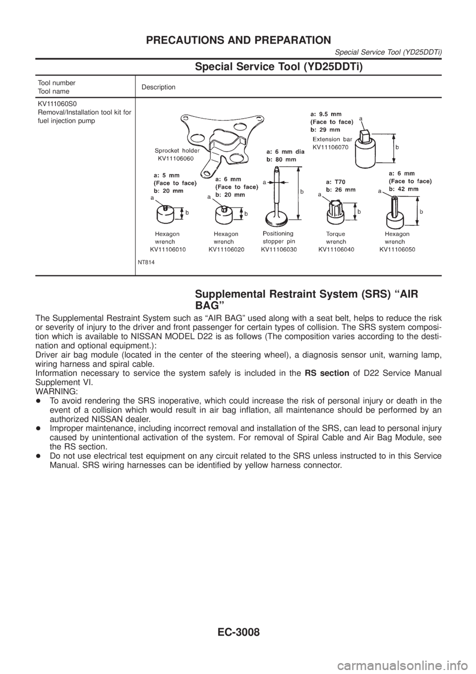
Special Service Tool (YD25DDTi)
Tool number
Tool nameDescription
KV111060S0
Removal/Installation tool kit for
fuel injection pump
NT814
Supplemental Restraint System (SRS) ªAIR
BAGº
The Supplemental Restraint System such as ªAIR BAGº used along with a seat belt, helps to reduce the risk
or severity of injury to the driver and front passenger for certain types of collision. The SRS system composi-
tion which is available to NISSAN MODEL D22 is as follows (The composition varies according to the desti-
nation and optional equipment.):
Driver air bag module (located in the center of the steering wheel), a diagnosis sensor unit, warning lamp,
wiring harness and spiral cable.
Information necessary to service the system safely is included in theRS sectionof D22 Service Manual
Supplement VI.
WARNING:
+To avoid rendering the SRS inoperative, which could increase the risk of personal injury or death in the
event of a collision which would result in air bag inflation, all maintenance should be performed by an
authorized NISSAN dealer.
+Improper maintenance, including incorrect removal and installation of the SRS, can lead to personal injury
caused by unintentional activation of the system. For removal of Spiral Cable and Air Bag Module, see
the RS section.
+Do not use electrical test equipment on any circuit related to the SRS unless instructed to in this Service
Manual. SRS wiring harnesses can be identified by yellow harness connector.
PRECAUTIONS AND PREPARATION
Special Service Tool (YD25DDTi)
EC-3008
Page 34 of 1306
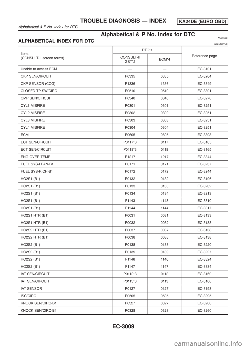
Alphabetical & P No. Index for DTCNEEC0001ALPHABETICAL INDEX FOR DTCNEEC0001S01
Items
(CONSULT-II screen terms)DTC*1
Reference page
CONSULT-II
GST*2ECM*4
Unable to access ECM Ð Ð EC-3101
CKP SEN/CIRCUIT P0335 0335 EC-3264
CKP SENSOR (COG) P1336 1336 EC-3349
CLOSED TP SW/CIRC P0510 0510 EC-3301
CMP SEN/CIRCUIT P0340 0340 EC-3270
CYL1 MISFIRE P0301 0301 EC-3251
CYL2 MISFIRE P0302 0302 EC-3251
CYL3 MISFIRE P0303 0303 EC-3251
CYL4 MISFIRE P0304 0304 EC-3251
ECM P0605 0605 EC-3308
ECT SEN/CIRCUIT P0117*3 0117 EC-3165
ECT SEN/CIRCUIT P0118*3 0118 EC-3165
ENG OVER TEMP P1217 1217 EC-3344
FUEL SYS-LEAN-B1 P0171 0171 EC-3237
FUEL SYS-RICH-B1 P0172 0172 EC-3244
HO2S1 (B1) P0132 0132 EC-3196
HO2S1 (B1) P0133 0133 EC-3202
HO2S1 (B1) P0134 0134 EC-3213
HO2S1 (B1) P1143 1143 EC-3310
HO2S1 (B1) P1144 1144 EC-3317
HO2S1 HTR (B1) P0031 0031 EC-3133
HO2S1 HTR (B1) P0032 0032 EC-3133
HO2S2 HTR (B1) P0037 0037 EC-3138
HO2S2 HTR (B1) P0038 0038 EC-3138
HO2S2 (B1) P0138 0138 EC-3220
HO2S2 (B1) P0139 0139 EC-3227
HO2S2 (B1) P1146 1146 EC-3324
HO2S2 (B1) P1147 1147 EC-3334
IAT SEN/CIRCUIT P0112*3 0112 EC-3160
IAT SEN/CIRCUIT P0113*3 0113 EC-3160
IAT SENSOR P0127 0127 EC-3193
ISC/CIRC P0505 0505 EC-3295
KNOCK SEN/CIRC-B1 P0327 0327 EC-3260
KNOCK SEN/CIRC-B1 P0328 0328 EC-3260
TROUBLE DIAGNOSIS Ð INDEXKA24DE (EURO OBD)
Alphabetical & P No. Index for DTC
EC-3009
Page 36 of 1306
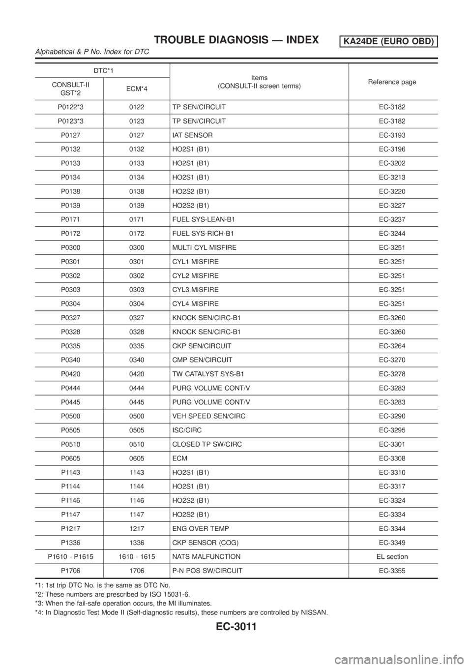
DTC*1
Items
(CONSULT-II screen terms)Reference page
CONSULT-II
GST*2ECM*4
P0122*3 0122 TP SEN/CIRCUIT EC-3182
P0123*3 0123 TP SEN/CIRCUIT EC-3182
P0127 0127 IAT SENSOR EC-3193
P0132 0132 HO2S1 (B1) EC-3196
P0133 0133 HO2S1 (B1) EC-3202
P0134 0134 HO2S1 (B1) EC-3213
P0138 0138 HO2S2 (B1) EC-3220
P0139 0139 HO2S2 (B1) EC-3227
P0171 0171 FUEL SYS-LEAN-B1 EC-3237
P0172 0172 FUEL SYS-RICH-B1 EC-3244
P0300 0300 MULTI CYL MISFIRE EC-3251
P0301 0301 CYL1 MISFIRE EC-3251
P0302 0302 CYL2 MISFIRE EC-3251
P0303 0303 CYL3 MISFIRE EC-3251
P0304 0304 CYL4 MISFIRE EC-3251
P0327 0327 KNOCK SEN/CIRC-B1 EC-3260
P0328 0328 KNOCK SEN/CIRC-B1 EC-3260
P0335 0335 CKP SEN/CIRCUIT EC-3264
P0340 0340 CMP SEN/CIRCUIT EC-3270
P0420 0420 TW CATALYST SYS-B1 EC-3278
P0444 0444 PURG VOLUME CONT/V EC-3283
P0445 0445 PURG VOLUME CONT/V EC-3283
P0500 0500 VEH SPEED SEN/CIRC EC-3290
P0505 0505 ISC/CIRC EC-3295
P0510 0510 CLOSED TP SW/CIRC EC-3301
P0605 0605 ECM EC-3308
P1143 1143 HO2S1 (B1) EC-3310
P1144 1144 HO2S1 (B1) EC-3317
P1146 1146 HO2S2 (B1) EC-3324
P1147 1147 HO2S2 (B1) EC-3334
P1217 1217 ENG OVER TEMP EC-3344
P1336 1336 CKP SENSOR (COG) EC-3349
P1610 - P1615 1610 - 1615 NATS MALFUNCTION EL section
P1706 1706 P-N POS SW/CIRCUIT EC-3355
*1: 1st trip DTC No. is the same as DTC No.
*2: These numbers are prescribed by ISO 15031-6.
*3: When the fail-safe operation occurs, the MI illuminates.
*4: In Diagnostic Test Mode II (Self-diagnostic results), these numbers are controlled by NISSAN.
TROUBLE DIAGNOSIS Ð INDEXKA24DE (EURO OBD)
Alphabetical & P No. Index for DTC
EC-3011
Page 37 of 1306
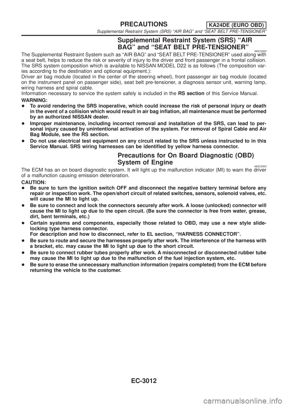
Supplemental Restraint System (SRS) ªAIR
BAGº and ªSEAT BELT PRE-TENSIONERº
NEEC0002The Supplemental Restraint System such as ªAIR BAGº and ªSEAT BELT PRE-TENSIONERº used along with
a seat belt, helps to reduce the risk or severity of injury to the driver and front passenger in a frontal collision.
The SRS system composition which is available to NISSAN MODEL D22 is as follows (The composition var-
ies according to the destination and optional equipment.):
Driver air bag module (located in the center of the steering wheel), front passenger air bag module (located
on the instrument panel on passenger side), seat belt pre-tensioner, a diagnosis sensor unit, warning lamp,
wiring harness and spiral cable.
Information necessary to service the system safely is included in theRS sectionof this Service Manual.
WARNING:
+To avoid rendering the SRS inoperative, which could increase the risk of personal injury or death
in the event of a collision which would result in air bag inflation, all maintenance must be performed
by an authorized NISSAN dealer.
+Improper maintenance, including incorrect removal and installation of the SRS, can lead to per-
sonal injury caused by unintentional activation of the system. For removal of Spiral Cable and Air
Bag Module, see the RS section.
+Do not use electrical test equipment on any circuit related to the SRS unless instructed to in this
Service Manual. SRS wiring harnesses can be identified by yellow harness connector.
Precautions for On Board Diagnostic (OBD)
System of Engine
NEEC0003The ECM has an on board diagnostic system. It will light up the malfunction indicator (MI) to warn the driver
of a malfunction causing emission deterioration.
CAUTION:
+Be sure to turn the ignition switch OFF and disconnect the negative battery terminal before any
repair or inspection work. The open/short circuit of related switches, sensors, solenoid valves, etc.
will cause the MI to light up.
+Be sure to connect and lock the connectors securely after work. A loose (unlocked) connector will
cause the MI to light up due to the open circuit. (Be sure the connector is free from water, grease,
dirt, bent terminals, etc.)
+Certain systems and components, especially those related to OBD, may use a new style slide-
locking type harness connector.
For description and how to disconnect, refer to EL section, ªHARNESS CONNECTORº.
+Be sure to route and secure the harnesses properly after work. The interference of the harness with
a bracket, etc. may cause the MI to light up due to the short circuit.
+Be sure to connect rubber tubes properly after work. A misconnected or disconnected rubber tube
may cause the MI to light up due to the malfunction of the fuel injection system, etc.
+Be sure to erase the unnecessary malfunction information (repairs completed) from the ECM before
returning the vehicle to the customer.
PRECAUTIONSKA24DE (EURO OBD)
Supplemental Restraint System (SRS) ªAIR BAGº and ªSEAT BELT PRE-TENSIONERº
EC-3012