light NISSAN PICK-UP 2001 Repair Manual
[x] Cancel search | Manufacturer: NISSAN, Model Year: 2001, Model line: PICK-UP, Model: NISSAN PICK-UP 2001Pages: 1306, PDF Size: 31.7 MB
Page 37 of 1306
Supplemental Restraint System (SRS) ªAIR
BAGº and ªSEAT BELT PRE-TENSIONERº
NEEC0002The Supplemental Restraint System such as ªAIR BAGº and ªSEAT BELT PRE-TENSIONERº used along with
a seat belt, helps to reduce the risk or severity of injury to the driver and front passenger in a frontal collision.
The SRS system composition which is available to NISSAN MODEL D22 is as follows (The composition var-
ies according to the destination and optional equipment.):
Driver air bag module (located in the center of the steering wheel), front passenger air bag module (located
on the instrument panel on passenger side), seat belt pre-tensioner, a diagnosis sensor unit, warning lamp,
wiring harness and spiral cable.
Information necessary to service the system safely is included in theRS sectionof this Service Manual.
WARNING:
+To avoid rendering the SRS inoperative, which could increase the risk of personal injury or death
in the event of a collision which would result in air bag inflation, all maintenance must be performed
by an authorized NISSAN dealer.
+Improper maintenance, including incorrect removal and installation of the SRS, can lead to per-
sonal injury caused by unintentional activation of the system. For removal of Spiral Cable and Air
Bag Module, see the RS section.
+Do not use electrical test equipment on any circuit related to the SRS unless instructed to in this
Service Manual. SRS wiring harnesses can be identified by yellow harness connector.
Precautions for On Board Diagnostic (OBD)
System of Engine
NEEC0003The ECM has an on board diagnostic system. It will light up the malfunction indicator (MI) to warn the driver
of a malfunction causing emission deterioration.
CAUTION:
+Be sure to turn the ignition switch OFF and disconnect the negative battery terminal before any
repair or inspection work. The open/short circuit of related switches, sensors, solenoid valves, etc.
will cause the MI to light up.
+Be sure to connect and lock the connectors securely after work. A loose (unlocked) connector will
cause the MI to light up due to the open circuit. (Be sure the connector is free from water, grease,
dirt, bent terminals, etc.)
+Certain systems and components, especially those related to OBD, may use a new style slide-
locking type harness connector.
For description and how to disconnect, refer to EL section, ªHARNESS CONNECTORº.
+Be sure to route and secure the harnesses properly after work. The interference of the harness with
a bracket, etc. may cause the MI to light up due to the short circuit.
+Be sure to connect rubber tubes properly after work. A misconnected or disconnected rubber tube
may cause the MI to light up due to the malfunction of the fuel injection system, etc.
+Be sure to erase the unnecessary malfunction information (repairs completed) from the ECM before
returning the vehicle to the customer.
PRECAUTIONSKA24DE (EURO OBD)
Supplemental Restraint System (SRS) ªAIR BAGº and ªSEAT BELT PRE-TENSIONERº
EC-3012
Page 63 of 1306
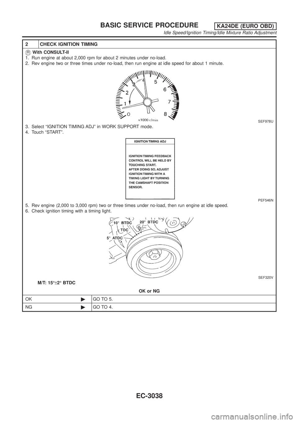
2 CHECK IGNITION TIMING
With CONSULT-II
1. Run engine at about 2,000 rpm for about 2 minutes under no-load.
2. Rev engine two or three times under no-load, then run engine at idle speed for about 1 minute.
SEF978U
3. Select ªIGNITION TIMING ADJº in WORK SUPPORT mode.
4. Touch ªSTARTº.
PEF546N
5. Rev engine (2,000 to 3,000 rpm) two or three times under no-load, then run engine at idle speed.
6. Check ignition timing with a timing light.
SEF320V
M/T: 15ɱ2É BTDC
OK or NG
OK©GO TO 5.
NG©GO TO 4.
BASIC SERVICE PROCEDUREKA24DE (EURO OBD)
Idle Speed/Ignition Timing/Idle Mixture Ratio Adjustment
EC-3038
Page 64 of 1306
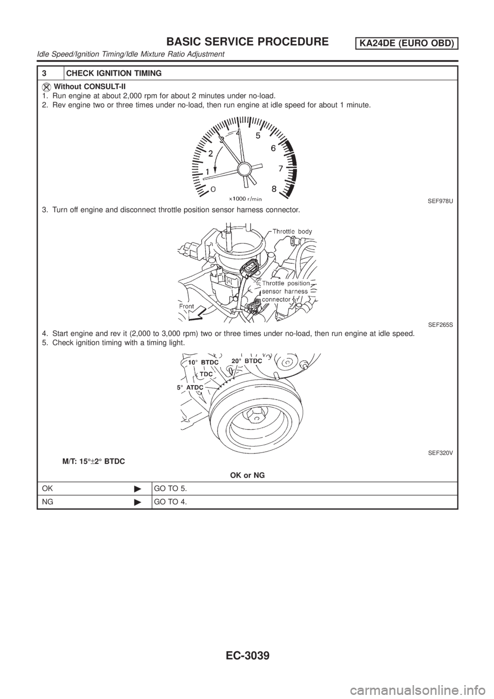
3 CHECK IGNITION TIMING
Without CONSULT-II
1. Run engine at about 2,000 rpm for about 2 minutes under no-load.
2. Rev engine two or three times under no-load, then run engine at idle speed for about 1 minute.
SEF978U
3. Turn off engine and disconnect throttle position sensor harness connector.
SEF265S
4. Start engine and rev it (2,000 to 3,000 rpm) two or three times under no-load, then run engine at idle speed.
5. Check ignition timing with a timing light.
SEF320V
M/T: 15ɱ2É BTDC
OK or NG
OK©GO TO 5.
NG©GO TO 4.
BASIC SERVICE PROCEDUREKA24DE (EURO OBD)
Idle Speed/Ignition Timing/Idle Mixture Ratio Adjustment
EC-3039
Page 74 of 1306
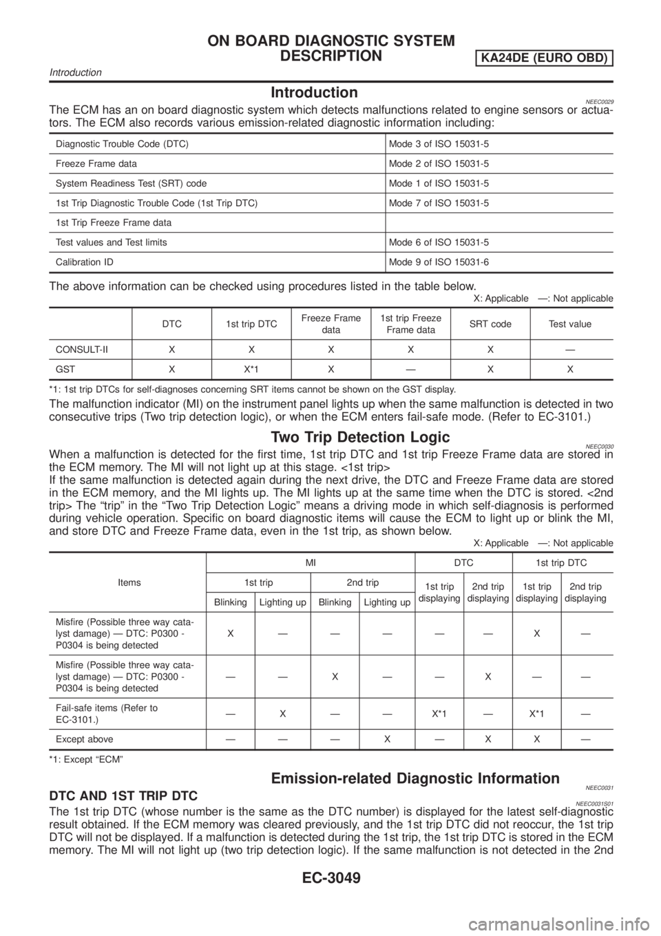
IntroductionNEEC0029The ECM has an on board diagnostic system which detects malfunctions related to engine sensors or actua-
tors. The ECM also records various emission-related diagnostic information including:
Diagnostic Trouble Code (DTC) Mode 3 of ISO 15031-5
Freeze Frame data Mode 2 of ISO 15031-5
System Readiness Test (SRT) code Mode 1 of ISO 15031-5
1st Trip Diagnostic Trouble Code (1st Trip DTC) Mode 7 of ISO 15031-5
1st Trip Freeze Frame data
Test values and Test limits Mode 6 of ISO 15031-5
Calibration ID Mode 9 of ISO 15031-6
The above information can be checked using procedures listed in the table below.
X: Applicable Ð: Not applicable
DTC 1st trip DTCFreeze Frame
data1st trip Freeze
Frame dataSRT code Test value
CONSULT-IIXXXXXÐ
GST X X*1 X Ð X X
*1: 1st trip DTCs for self-diagnoses concerning SRT items cannot be shown on the GST display.
The malfunction indicator (MI) on the instrument panel lights up when the same malfunction is detected in two
consecutive trips (Two trip detection logic), or when the ECM enters fail-safe mode. (Refer to EC-3101.)
Two Trip Detection LogicNEEC0030When a malfunction is detected for the first time, 1st trip DTC and 1st trip Freeze Frame data are stored in
the ECM memory. The MI will not light up at this stage. <1st trip>
If the same malfunction is detected again during the next drive, the DTC and Freeze Frame data are stored
in the ECM memory, and the MI lights up. The MI lights up at the same time when the DTC is stored. <2nd
trip> The ªtripº in the ªTwo Trip Detection Logicº means a driving mode in which self-diagnosis is performed
during vehicle operation. Specific on board diagnostic items will cause the ECM to light up or blink the MI,
and store DTC and Freeze Frame data, even in the 1st trip, as shown below.
X: Applicable Ð: Not applicable
ItemsMI DTC 1st trip DTC
1st trip 2nd trip
1st trip
displaying2nd trip
displaying1st trip
displaying2nd trip
displaying
Blinking Lighting up Blinking Lighting up
Misfire (Possible three way cata-
lyst damage) Ð DTC: P0300 -
P0304 is being detectedX ÐÐÐÐÐXÐ
Misfire (Possible three way cata-
lyst damage) Ð DTC: P0300 -
P0304 is being detectedÐÐ X ÐÐXÐÐ
Fail-safe items (Refer to
EC-3101.)Ð X Ð Ð X*1 Ð X*1 Ð
Except above Ð Ð Ð X Ð X X Ð
*1: Except ªECMº
Emission-related Diagnostic InformationNEEC0031DTC AND 1ST TRIP DTCNEEC0031S01The 1st trip DTC (whose number is the same as the DTC number) is displayed for the latest self-diagnostic
result obtained. If the ECM memory was cleared previously, and the 1st trip DTC did not reoccur, the 1st trip
DTC will not be displayed. If a malfunction is detected during the 1st trip, the 1st trip DTC is stored in the ECM
memory. The MI will not light up (two trip detection logic). If the same malfunction is not detected in the 2nd
ON BOARD DIAGNOSTIC SYSTEM
DESCRIPTION
KA24DE (EURO OBD)
Introduction
EC-3049
Page 75 of 1306
trip (meeting the required driving pattern), the 1st trip DTC is cleared from the ECM memory. If the same mal-
function is detected in the 2nd trip, both the 1st trip DTC and DTC are stored in the ECM memory and the MI
lights up. In other words, the DTC is stored in the ECM memory and the MI lights up when the same malfunc-
tion occurs in two consecutive trips. If a 1st trip DTC is stored and a non-diagnostic operation is performed
between the 1st and 2nd trips, only the 1st trip DTC will continue to be stored. For malfunctions that blink or
light up the MI during the 1st trip, the DTC and 1st trip DTC are stored in the ECM memory.
Procedures for clearing the DTC and the 1st trip DTC from the ECM memory are described in ªHOW TO
ERASE EMISSION-RELATED DIAGNOSTIC INFORMATIONº. Refer to EC-3060.
For malfunctions in which 1st trip DTCs are displayed, refer to EC-3058. These items are required by legal
regulations to continuously monitor the system/component. In addition, the items monitored non-continuously
are also displayed on CONSULT-II.
1st trip DTC is specified in Mode 7 of ISO 15031-5. 1st trip DTC detection occurs without lighting up the MI
and therefore does not warn the driver of a problem. However, 1st trip DTC detection will not prevent the
vehicle from being tested, for example during Inspection/Maintenance (I/M) tests.
When a 1st trip DTC is detected, check, print out or write down and erase (1st trip) DTC and Freeze Frame
data as specified in ªWork Flowº procedure Step II, refer to page EC-3084. Then perform ªDTC Confirmation
Procedureº or ªOverall Function Checkº to try to duplicate the problem. If the malfunction is duplicated, the
item requires repair.
How to read DTC and 1st Trip DTCNEEC0031S0101DTC and 1st trip DTC can be read by the following methods.
With CONSULT-II
With GST
CONSULT-II or GST (Generic Scan Tool) Examples: P0340 etc.
These DTCs are prescribed by ISO 15031-5.
(CONSULT-II also displays the malfunctioning component or system.)
+1st trip DTC No. is the same as DTC No.
+Output of a DTC indicates a malfunction. However, GST does not indicate whether the malfunction
is still occurring or has occurred in the past and has returned to normal.
CONSULT-II can identify malfunction status as shown below. Therefore, using CONSULT-II (if avail-
able) is recommended.
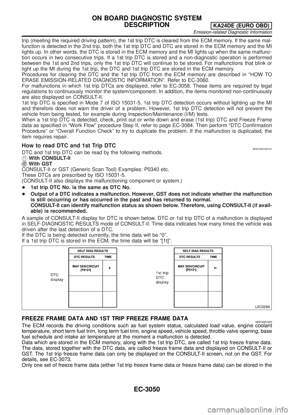
A sample of CONSULT-II display for DTC is shown below. DTC or 1st trip DTC of a malfunction is displayed
in SELF-DIAGNOSTIC RESULTS mode of CONSULT-II. Time data indicates how many times the vehicle was
driven after the last detection of a DTC.
If the DTC is being detected currently, the time data will be ª0º.
If a 1st trip DTC is stored in the ECM, the time data will be ª[1t]º.
LEC028A
FREEZE FRAME DATA AND 1ST TRIP FREEZE FRAME DATANEEC0031S02The ECM records the driving conditions such as fuel system status, calculated load value, engine coolant
temperature, short term fuel trim, long term fuel trim, engine speed, vehicle speed, throttle valve opening, base
fuel schedule and intake air temperature at the moment a malfunction is detected.
Data which are stored in the ECM memory, along with the 1st trip DTC, are called 1st trip freeze frame data.
The data, stored together with the DTC data, are called freeze frame data and displayed on CONSULT-II or
GST. The 1st trip freeze frame data can only be displayed on the CONSULT-II screen, not on the GST. For
details, see EC-3073.
Only one set of freeze frame data (either 1st trip freeze frame data or freeze frame data) can be stored in the
ON BOARD DIAGNOSTIC SYSTEM
DESCRIPTION
KA24DE (EURO OBD)
Emission-related Diagnostic Information
EC-3050
Page 86 of 1306
Actual work procedures are explained using a DTC as an example. Be careful so that not only the DTC, but
all of the data listed above, are cleared from the ECM memory during work procedures.
NVIS (Nissan Vehicle Immobilizer System Ð
NATS)
NEEC1601
SEF515Y
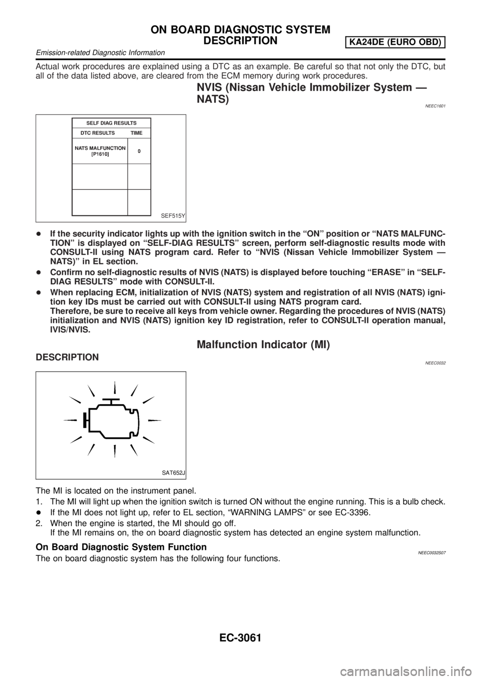
+If the security indicator lights up with the ignition switch in the ªONº position or ªNATS MALFUNC-
TIONº is displayed on ªSELF-DIAG RESULTSº screen, perform self-diagnostic results mode with
CONSULT-II using NATS program card. Refer to ªNVIS (Nissan Vehicle Immobilizer System Ð
NATS)º in EL section.
+Confirm no self-diagnostic results of NVIS (NATS) is displayed before touching ªERASEº in ªSELF-
DIAG RESULTSº mode with CONSULT-II.
+When replacing ECM, initialization of NVIS (NATS) system and registration of all NVIS (NATS) igni-
tion key IDs must be carried out with CONSULT-II using NATS program card.
Therefore, be sure to receive all keys from vehicle owner. Regarding the procedures of NVIS (NATS)
initialization and NVIS (NATS) ignition key ID registration, refer to CONSULT-II operation manual,
IVIS/NVIS.
Malfunction Indicator (MI)
DESCRIPTIONNEEC0032
SAT652J
The MI is located on the instrument panel.
1. The MI will light up when the ignition switch is turned ON without the engine running. This is a bulb check.
+If the MI does not light up, refer to EL section, ªWARNING LAMPSº or see EC-3396.
2. When the engine is started, the MI should go off.
If the MI remains on, the on board diagnostic system has detected an engine system malfunction.
On Board Diagnostic System FunctionNEEC0032S07The on board diagnostic system has the following four functions.
ON BOARD DIAGNOSTIC SYSTEM
DESCRIPTION
KA24DE (EURO OBD)
Emission-related Diagnostic Information
EC-3061
Page 87 of 1306
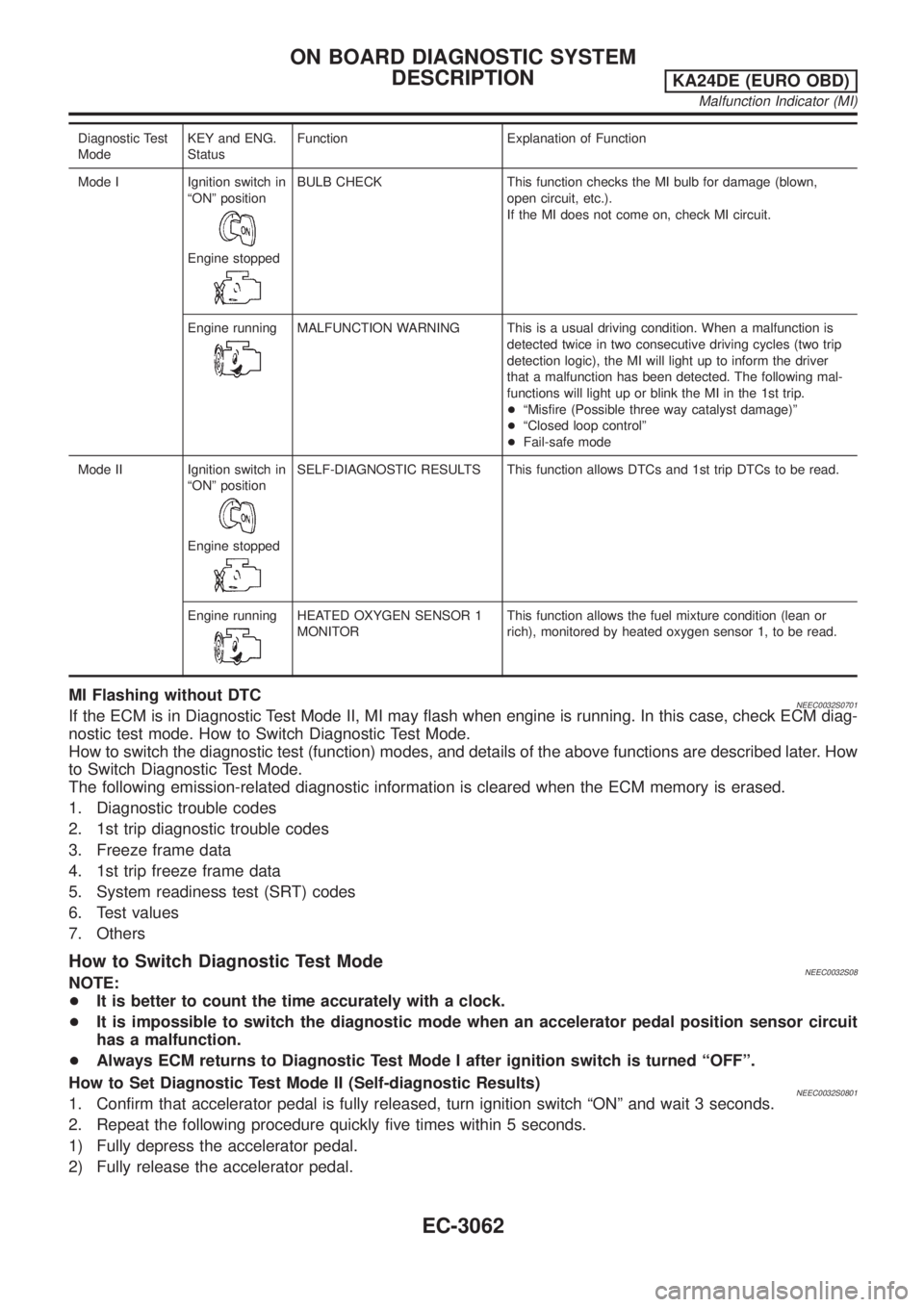
Diagnostic Test
ModeKEY and ENG.
StatusFunction Explanation of Function
Mode I Ignition switch in
ªONº position
Engine stopped
BULB CHECK This function checks the MI bulb for damage (blown,
open circuit, etc.).
If the MI does not come on, check MI circuit.
Engine running
MALFUNCTION WARNING This is a usual driving condition. When a malfunction is
detected twice in two consecutive driving cycles (two trip
detection logic), the MI will light up to inform the driver
that a malfunction has been detected. The following mal-
functions will light up or blink the MI in the 1st trip.
+ªMisfire (Possible three way catalyst damage)º
+ªClosed loop controlº
+Fail-safe mode
Mode II Ignition switch in
ªONº position
Engine stopped
SELF-DIAGNOSTIC RESULTS This function allows DTCs and 1st trip DTCs to be read.
Engine running
HEATED OXYGEN SENSOR 1
MONITORThis function allows the fuel mixture condition (lean or
rich), monitored by heated oxygen sensor 1, to be read.
MI Flashing without DTCNEEC0032S0701If the ECM is in Diagnostic Test Mode II, MI may flash when engine is running. In this case, check ECM diag-
nostic test mode. How to Switch Diagnostic Test Mode.
How to switch the diagnostic test (function) modes, and details of the above functions are described later. How
to Switch Diagnostic Test Mode.
The following emission-related diagnostic information is cleared when the ECM memory is erased.
1. Diagnostic trouble codes
2. 1st trip diagnostic trouble codes
3. Freeze frame data
4. 1st trip freeze frame data
5. System readiness test (SRT) codes
6. Test values
7. Others
How to Switch Diagnostic Test ModeNEEC0032S08NOTE:
+It is better to count the time accurately with a clock.
+It is impossible to switch the diagnostic mode when an accelerator pedal position sensor circuit
has a malfunction.
+Always ECM returns to Diagnostic Test Mode I after ignition switch is turned ªOFFº.
How to Set Diagnostic Test Mode II (Self-diagnostic Results)
NEEC0032S08011. Confirm that accelerator pedal is fully released, turn ignition switch ªONº and wait 3 seconds.
2. Repeat the following procedure quickly five times within 5 seconds.
1) Fully depress the accelerator pedal.
2) Fully release the accelerator pedal.
ON BOARD DIAGNOSTIC SYSTEM
DESCRIPTION
KA24DE (EURO OBD)
Malfunction Indicator (MI)
EC-3062
Page 91 of 1306

RELATIONSHIP BETWEEN MI, DTC, 1ST TRIP DTC AND DRIVING PATTERNS FOR
ªMISFIREº
=NEEC0033S03
SEF392SC
*1: When the same malfunction is
detected in two consecutive trips,
MI will light up.
*2: MI will go off after vehicle is driven
3 times (pattern B) without any
malfunctions.
*3: When the same malfunction is
detected in two consecutive trips,
the DTC and the freeze frame
data will be stored in ECM.
*4: The DTC and the freeze framedata will not be displayed any
longer after vehicle is driven 80
times (pattern C) without the same
malfunction.
(The DTC and the freeze frame
data still remain in ECM.)
*5: When a malfunction is detected
for the first time, the 1st trip DTC
and the 1st trip freeze frame data
will be stored in ECM.
*6: The 1st trip DTC and the 1st tripfreeze frame data will be cleared
at the moment OK is detected.
*7: When the same malfunction is
detected in the 2nd trip, the 1st
trip freeze frame data will be
cleared.
*8: 1st trip DTC will be cleared when
vehicle is driven once (pattern C)
without the same malfunction after
DTC is stored in ECM.
ON BOARD DIAGNOSTIC SYSTEM
DESCRIPTION
KA24DE (EURO OBD)
OBD System Operation Chart
EC-3066
Page 93 of 1306

RELATIONSHIP BETWEEN MI, DTC, 1ST TRIP DTC AND DRIVING PATTERNS EXCEPTFOR
ªMISFIRE
NEEC0033S05
SEF393SC
*1: When the same malfunction is
detected in two consecutive trips,
MI will light up.
*2: MI will go off after vehicle is driven
3 times (pattern B) without any
malfunctions.
*3: When the same malfunction is
detected in two consecutive trips,
the DTC and the freeze frame
data will be stored in ECM.*4: The DTC and the freeze frame
data will not be displayed any
longer after vehicle is driven 40
times (pattern A) without the same
malfunction.
(The DTC and the freeze frame
data still remain in ECM.)
*5: When a malfunction is detected
for the first time, the 1st trip DTCand the 1st trip freeze frame data
will be stored in ECM.
*6: 1st trip DTC will be cleared after
vehicle is driven once (pattern B)
without the same malfunction.
*7: When the same malfunction is
detected in the 2nd trip, the 1st
trip freeze frame data will be
cleared.
ON BOARD DIAGNOSTIC SYSTEM
DESCRIPTION
KA24DE (EURO OBD)
OBD System Operation Chart
EC-3068
Page 98 of 1306
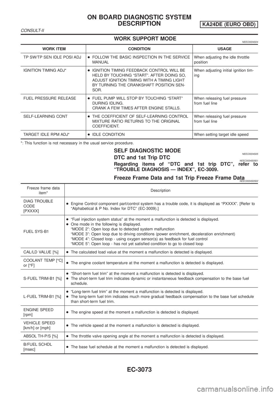
WORK SUPPORT MODENEEC0034S04
WORK ITEM CONDITION USAGE
TP SW/TP SEN IDLE POSI ADJ+FOLLOW THE BASIC INSPECTION IN THE SERVICE
MANUALWhen adjusting the idle throttle
position
IGNITION TIMING ADJ*+IGNITION TIMING FEEDBACK CONTROL WILL BE
HELD BY TOUCHING ªSTARTº. AFTER DOING SO,
ADJUST IGNITION TIMING WITH A TIMING LIGHT
BY TURNING THE CRANKSHAFT POSITION SEN-
SOR.When adjusting initial ignition tim-
ing
FUEL PRESSURE RELEASE+FUEL PUMP WILL STOP BY TOUCHING ªSTARTº
DURING IDLING.
CRANK A FEW TIMES AFTER ENGINE STALLS.When releasing fuel pressure
from fuel line
SELF-LEARNING CONT+THE COEFFICIENT OF SELF-LEARNING CONTROL
MIXTURE RATIO RETURNS TO THE ORIGINAL
COEFFICIENT.When releasing fuel pressure
from fuel line
TARGET IDLE RPM ADJ*+IDLE CONDITION When setting target idle speed
*: This function is not necessary in the usual service procedure.
SELF DIAGNOSTIC MODENEEC0034S05DTC and 1st Trip DTCNEEC0034S0501Regarding items of ªDTC and 1st trip DTCº, refer to
ªTROUBLE DIAGNOSIS Ð INDEXº, EC-3009.
Freeze Frame Data and 1st Trip Freeze Frame DataNEEC0034S0502
Freeze frame data
item*Description
DIAG TROUBLE
CODE
[PXXXX]+Engine Control component part/control system has a trouble code, it is displayed as ªPXXXXº. [Refer to
ªAlphabetical & P No. Index for DTCº (EC-3009).]
FUEL SYS-B1+ªFuel injection system statusº at the moment a malfunction is detected is displayed.
+One mode in the following is displayed.
ªMODE 2º: Open loop due to detected system malfunction
ªMODE 3º: Open loop due to driving conditions (power enrichment, deceleration enrichment)
ªMODE 4º: Closed loop - using oxygen sensor(s) as feedback for fuel control
ªMODE 5º: Open loop - has not yet satisfied condition to go to closed loop
CAL/LD VALUE [%]+The calculated load value at the moment a malfunction is detected is displayed.
COOLANT TEMP [ÉC]
or [ÉF]+The engine coolant temperature at the moment a malfunction is detected is displayed.
S-FUEL TRIM-B1 [%]+ªShort-term fuel trimº at the moment a malfunction is detected is displayed.
+The short-term fuel trim indicates dynamic or instantaneous feedback compensation to the base fuel
schedule.
L-FUEL TRIM-B1 [%]+ªLong-term fuel trimº at the moment a malfunction is detected is displayed.
+The long-term fuel trim indicates much more gradual feedback compensation to the base fuel schedule
than short-term fuel trim.
ENGINE SPEED
[rpm]+The engine speed at the moment a malfunction is detected is displayed.
VEHICLE SPEED
[km/h] or [mph]+The vehicle speed at the moment a malfunction is detected is displayed.
ABSOL TH-P/S [%]+The throttle valve opening angle at the moment a malfunction is detected is displayed.
B/FUEL SCHDL
[msec]+The base fuel schedule at the moment a malfunction is detected is displayed.
ON BOARD DIAGNOSTIC SYSTEM
DESCRIPTION
KA24DE (EURO OBD)
CONSULT-II
EC-3073