dtc 34 NISSAN PRIMERA 1999 Electronic User Guide
[x] Cancel search | Manufacturer: NISSAN, Model Year: 1999, Model line: PRIMERA, Model: NISSAN PRIMERA 1999Pages: 2267, PDF Size: 35.74 MB
Page 21 of 2267

SELF-DIAGNOSTIC PROCEDURE
(WITH CONSULT-II)
NCAT0022S021. Turn on CONSULT-II and touch ªENGINEº for OBD detected
items or touch ªCVTº for TCM self-diagnosis.
If CVT is not displayed, check TCM power supply and ground
circuit. Refer to AT-41. If result is NG, refer to EL section
(ªPOWER SUPPLY ROUTINGº).
2. Touch ªSELF DIAGNOSISº.
Display shows malfunction experienced since the last erasing
operation.
CONSULT-II performs REAL-TIME SELF-DIAGNOSIS.
Also, any malfunction detected while in this mode will be dis-
played at real time.
SELF-DIAGNOSTIC RESULT TEST MODENCAT0022S03
Detected items
(Screen terms for CONSULT-II, ªSELF
DIAGNOSISº test mode)
Malfunction is detected when ...TCM self-diagnosis OBD (DTC)
Available by
CVT or SPORT
indicator lamp
ªCVTº on CON-
SULT-IIAvailable by
malfunction
indicator lamp*2,
ªENGINEº on CON-
SULT-II or GST ªCVTº ªENGINEº
PNP switch circuitITCM does not receive the correct volt-
age signal (based on the gear posi-
tion) from the switch.Ð P0705
PNP SW/CIRCUITPNP SW/CIRC
Primary speed sensorITCM does not receive the proper volt-
age signal from the sensor.
X P0715
I/P PULLY SPD SIGPRI SPEED SIG/
CIRC
Secondary speed sensorITCM does not receive the proper volt-
age signal from the sensor.
X P0720
VEHICLE SPEED
SIGVEH SPD SEN/CIR
A/T
T/C clutch solenoid valveITCM detects an improper voltage drop
when it tries to operate the solenoid
valve.X P0740
T/C CLUTCH
SOL/VTCC SOLENOID/
CIRC
Line pressure solenoid valveITCM detects an improper voltage drop
when it tries to operate the solenoid
valve.X P0745
LINE PRESSURE
S/VL/PRESS SOL/
CIRC
Throttle position sensor,
Throttle position switchITCM receives an excessively low or
high voltage from the sensor.
X P1705
THROTTLE POSI
SENTP SEN/CIRC A/T
SAT651J
SAT584J
ON BOARD DIAGNOSTIC SYSTEM DESCRIPTION
CONSULT-II (Cont'd)
AT-19
Page 22 of 2267
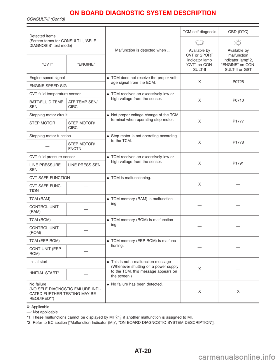
Detected items
(Screen terms for CONSULT-II, ªSELF
DIAGNOSISº test mode)
Malfunction is detected when ...TCM self-diagnosis OBD (DTC)
Available by
CVT or SPORT
indicator lamp
ªCVTº on CON-
SULT-IIAvailable by
malfunction
indicator lamp*2,
ªENGINEº on CON-
SULT-II or GST ªCVTº ªENGINEº
Engine speed signalITCM does not receive the proper volt-
age signal from the ECM.X P0725
ENGINE SPEED SIG
CVT fluid temperature sensorITCM receives an excessively low or
high voltage from the sensor.
X P0710
BATT/FLUID TEMP
SENATF TEMP SEN/
CIRC
Stepping motor circuitINot proper voltage change of the TCM
terminal when operating step motor.
X P1777
STEP MOTOR STEP MOTOR/
CIRC
Stepping motor functionIStep motor is not operating according
to the TCM.
X P1778
ÐSTEP MOTOR/
FNCTN
CVT fluid pressure sensorITCM receives an excessively low or
high voltage from the sensor.
X P1791
LINE PRESSURE
SENLINE PRESS SEN
CVT SAFE FUNCTIONITCM is malfunctioning.
XÐ
CVT SAFE FUNC-
TIONÐ
TCM (RAM)ITCM memory (RAM) is malfunction-
ing.
ÐÐ
CONTROL UNIT
(RAM)Ð
TCM (ROM)ITCM memory (ROM) is malfunction-
ing.
ÐÐ
CONTROL UNIT
(ROM)Ð
TCM (EEP ROM)ITCM memory (EEP ROM) is malfunc-
tioning.
ÐÐ
CONT UNIT (EEP
ROM)Ð
Initial startIThis is not a malfunction message
(Whenever shutting off a power supply
to the TCM, this message appears on
the screen.)XÐ
*INITIAL START*
Ð
No failure
(NO SELF DIAGNOSTIC FAILURE INDI-
CATED FURTHER TESTING MAY BE
REQUIRED**)INo failure has been detected.
XX
X: Applicable
Ð: Not applicable
*1: These malfunctions cannot be displayed by MI
if another malfunction is assigned to MI.
*2: Refer to EC section [ªMalfunction Indicator (MI)º, ªON BOARD DIAGNOSTIC SYSTEM DESCRIPTIONº].
ON BOARD DIAGNOSTIC SYSTEM DESCRIPTION
CONSULT-II (Cont'd)
AT-20
Page 28 of 2267

Judgement of Self-diagnosis CodeNCAT0022S0704
CVT or SPORT indicator lamp*
All judgement flickers are the same.
SAT436FA
All circuits that can be confirmed by self-diagnosis are OK.
Self diagnosis
start
Start signal 10 judgement flickers
Light
Shade
1st judgement flicker is longer than others.
SAT437FA Light
Shade
Secondary speed sensor (VEHICLE SPEED SENSOR CVT) cir-
cuit is short-circuited or disconnected.
ÞGo to VEHICLE SPEED SENSOR CVT (SECONDARY
SPEED SENSOR) (DTC: 0720), AT-62.
2nd judgement flicker is longer than others.
SAT439FA
Primary speed sensor circuit is short-circuited or disconnected.
ÞGo to PRIMARY SPEED SENSOR (DTC: 0715), AT-59.
Light
Shade
3rd judgement flicker is longer than others.
SAT441FA
Throttle position sensor circuit is short-circuited or disconnected.
ÞGo to THROTTLE POSITION SENSOR (DTC: 1705), AT-79.
Light
Shade
4th judgement flicker is longer than others.
SAT443FA
Step motor circuit is short-circuited or disconnected.
ÞGo to STEP MOTOR (DTC: 1777), AT-86.
Self diagnosis
start
Light
Shade
5th judgement flicker is longer than others.
SAT445FA Light
Shade
CVT fluid pressure sensor circuit is short-circuited or discon-
nected.
ÞGo to CVT FLUID PRESSURE SENSOR (DTC: 1791), AT-94.
ON BOARD DIAGNOSTIC SYSTEM DESCRIPTION
CONSULT-II (Cont'd)
AT-26
Page 29 of 2267
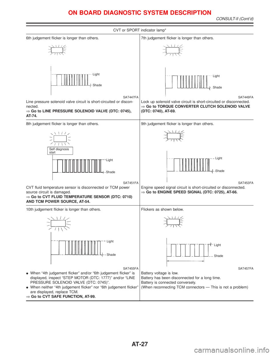
CVT or SPORT indicator lamp*
6th judgement flicker is longer than others.
SAT447FA
Line pressure solenoid valve circuit is short-circuited or discon-
nected.
ÞGo to LINE PRESSURE SOLENOID VALVE (DTC: 0745),
AT-74.
Light
Shade
7th judgement flicker is longer than others.
SAT449FA
Lock up solenoid valve circuit is short-circuited or disconnected.
ÞGo to TORQUE CONVERTER CLUTCH SOLENOID VALVE
(DTC: 0740), AT-69.
Light
Shade
8th judgement flicker is longer than others.
SAT451FA
CVT fluid temperature sensor is disconnected or TCM power
source circuit is damaged.
ÞGo to CVT FLUID TEMPERATURE SENSOR (DTC: 0710)
AND TCM POWER SOURCE, AT-54.
Self diagnosis
start
Light
Shade
9th judgement flicker is longer than others.
SAT453FA
Engine speed signal circuit is short-circuited or disconnected.
ÞGo to ENGINE SPEED SIGNAL (DTC: 0725), AT-66.
Light
Shade
10th judgement flicker is longer than others.
SAT455FA Light
Shade
IWhen ª4th judgement flickerº and/or ª6th judgement flickerº is
displayed, inspect ªSTEP MOTOR (DTC: 1777)º and/or ªLINE
PRESSURE SOLENOID VALVE (DTC: 0745)º.
IWhen neither ª4th judgement flickerº nor ª6th judgement flickerº
are displayed, replace TCM.
ÞGo to CVT SAFE FUNCTION, AT-99.Flickers as shown below.
SAT457FA
Battery voltage is low.
Battery has been disconnected for a long time.
Battery is connected conversely.
(When reconnecting TCM connectors Ð This is not a problem)
Light
Shade
ON BOARD DIAGNOSTIC SYSTEM DESCRIPTION
CONSULT-II (Cont'd)
AT-27
Page 33 of 2267
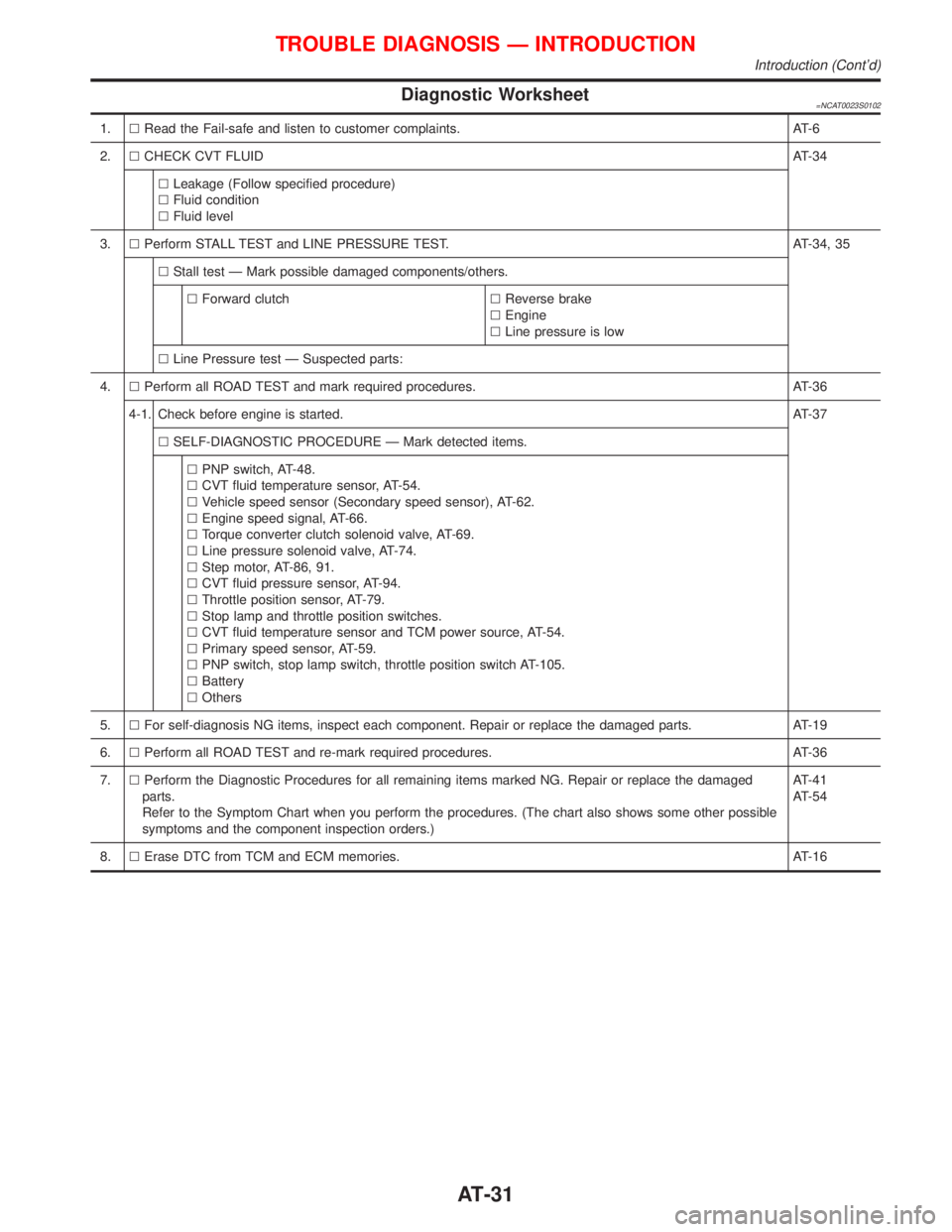
Diagnostic Worksheet=NCAT0023S0102
1.lRead the Fail-safe and listen to customer complaints. AT-6
2.lCHECK CVT FLUIDAT-34
lLeakage (Follow specified procedure)
lFluid condition
lFluid level
3.lPerform STALL TEST and LINE PRESSURE TEST. AT-34, 35
lStall test Ð Mark possible damaged components/others.
lForward clutchlReverse brake
lEngine
lLine pressure is low
lLine Pressure test Ð Suspected parts:
4.lPerform all ROAD TEST and mark required procedures. AT-36
4-1. Check before engine is started.AT-37
lSELF-DIAGNOSTIC PROCEDURE Ð Mark detected items.
lPNP switch, AT-48.
lCVT fluid temperature sensor, AT-54.
lVehicle speed sensor (Secondary speed sensor), AT-62.
lEngine speed signal, AT-66.
lTorque converter clutch solenoid valve, AT-69.
lLine pressure solenoid valve, AT-74.
lStep motor, AT-86, 91.
lCVT fluid pressure sensor, AT-94.
lThrottle position sensor, AT-79.
lStop lamp and throttle position switches.
lCVT fluid temperature sensor and TCM power source, AT-54.
lPrimary speed sensor, AT-59.
lPNP switch, stop lamp switch, throttle position switch AT-105.
lBattery
lOthers
5.lFor self-diagnosis NG items, inspect each component. Repair or replace the damaged parts. AT-19
6.lPerform all ROAD TEST and re-mark required procedures. AT-36
7.lPerform the Diagnostic Procedures for all remaining items marked NG. Repair or replace the damaged
parts.
Refer to the Symptom Chart when you perform the procedures. (The chart also shows some other possible
symptoms and the component inspection orders.)AT-41
AT-54
8.lErase DTC from TCM and ECM memories. AT-16
TROUBLE DIAGNOSIS Ð INTRODUCTION
Introduction (Cont'd)
AT-31
Page 35 of 2267

WORK FLOW CHART=NCAT0024S02
CHECK IN
LISTEN TO CUSTOMER COMPLAINTS AND FILL OUT
ªINFORMATION FROM CUSTOMERº, *1FRefer to FAIL-SAFE Service Notice or
Precautions, *3.
CHECK,PRINT OUTOR WRITE DOWN (1ST TRIP) DTC AND
FREEZE FRAME DATA. (PRE-CHECK) THEN ERASE.
PASTE IT IN REPAIR ORDER SHEET.
ALSO CHECK RELATED SERVICE BULLETINS.
CHECK A/T FLUID LEVEL AND CONDITION. IF NG, PLACE
CHECK ON THE DIAGNOSTIC WORKSHEET, *2.FRefer to CVT Fluid Check, *4.
PERFORM STALL TEST AND LINE PRESSURE TEST.FRefer to Stall Test and Line Pressure Test, *5.
PERFORM ªDTC CONFIRMATION PROCEDUREº IF THE (1ST
TRIP) DTC IS AVAILABLE.
PERFORM ROAD TEST AND PLACE CHECKS FOR NG ITEMS
ON THE DIAGNOSTIC WORKSHEET.
H
No NG item or NG items
not including any OBD
DTC or TCM self-diagnostic
itemsNG items including OBD
(1st trip) DTC or TCM self-
diagnostic item
FFollow ROAD TEST procedure, *6.
lFOR OBD or TCM SELF-DIAGNOSIS NG ITEMS:
-INSPECT EACH COMPONENT.
-REPAIR/REPLACE.
lPERFORM DTC CONFIRMATION PROCEDURE OR
ROAD TEST AND PLACE CHECKS FOR NG ITEMS
ON THE DIAGNOSTIC WORKSHEET AGAIN.
FlRefer to CONSULT-II, *7.
lPerform ROAD TEST for all items.
lProceed if self-diagnosis detects no malfunc-
tion.
(Non-self-diagnostic items, especially those
that require CVT removal, should be repaired
in the following steps.)
ElFOR ALL REMAINING MALFUNCTIONS:
-INSPECT EACH COMPONENT.
-REPAIR/REPLACE.
lPERFORM ROAD TEST AND CONFIRM ALL MALFUNCTIONS
ARE ELIMINATED.
FRefer to
lON BOARD DIAGNOSTIC SYSTEM
DESCRIPTION, *8 - *9.
lTROUBLE DIAGNOSIS FOR DTC, *10 - *11.
lTROUBLE DIAGNOSES FOR SYMPTOMS,
*12.
ERASE DTC FROM TCM AND ECM MEMORIES.FRefer to HOW TO ERASE DTC, *13.
NGFINAL CHECK
Confirm that the incident is completely fixed by performing BASIC
INSPECTION and DTC CONFIRMATION PROCEDURE. Then,
erase the unnecessary (already fixed) 1st trip DTCs in ECM and
TCM.FRefer to DTC CONFIRMATION PROCEDURE.
*14 - *15.
EOK
CHECK OUT
SAT086JC
*1: AT-30
*2: AT-31
*3: AT-6
*4: AT-34
*5: AT-34, 35*6: AT-36
*7: AT-18
*8: AT-15
*9: AT-26
*10: AT-48*11: AT-94
*12: AT-110
*13: AT-16
*14: AT-49
*15: AT-95
TROUBLE DIAGNOSIS Ð INTRODUCTION
Work Flow (Cont'd)
H
H
H
H
H
H
H
H
H
AT-33
Page 47 of 2267
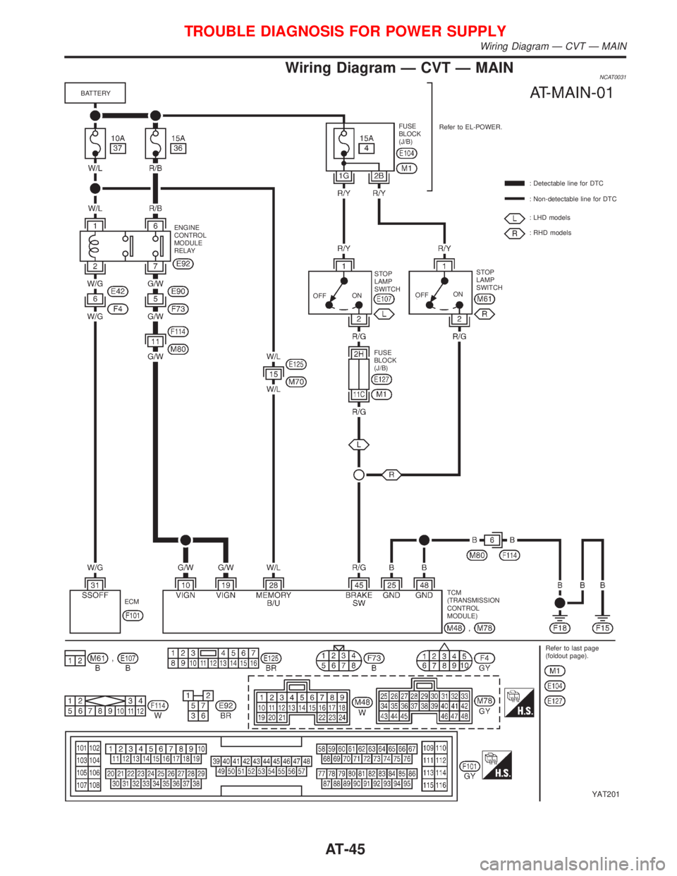
Wiring Diagram Ð CVT Ð MAINNCAT0031
YAT201
BATTERY
ENGINE
CONTROL
MODULE
RELAY
OFFONSTOP
LAMP
SWITCH
FUSE
BLOCK
(J/B)OFFONSTOP
LAMP
SWITCH: Detectable line for DTC
: Non-detectable line for DTC
: LHD models
: RHD models Refer to EL-POWER. FUSE
BLOCK
(J/B)
TCM
(TRANSMISSION
CONTROL
MODULE)
Refer to last page
(foldout page). ECM
TROUBLE DIAGNOSIS FOR POWER SUPPLY
Wiring Diagram Ð CVT Ð MAIN
AT-45
Page 50 of 2267

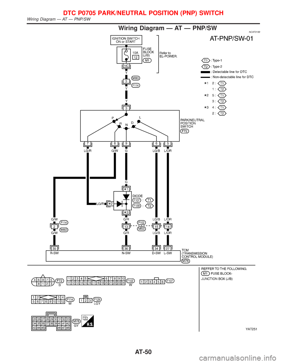
DescriptionNCAT0032IThe PNP switch assembly includes a transmission range
switch.
IThe transmission range switch detects the selector lever posi-
tion and sends a signal to the TCM.
TCM TERMINALS AND REFERENCE VALUENCAT0032S01Remarks: Specification data are reference values.
Terminal
No.Wire color Item ConditionJudgement
standard
27 L/ORPNP switch ªLº
position
When setting selector lever to ªLº
position.Battery voltage
When setting selector lever to
other positions.Approx. 0V
34 LGPNP switch ªDº
positionWhen setting selector lever to ªDº
position.Battery voltage
When setting selector lever to
other positions.Approx. 0V
35 G/WPNP switch ªRº
positionWhen setting selector lever to ªRº
position.Battery voltage
When setting selector lever to
other positions.Approx. 0V
36 G/RPNP switch ªNº or
ªPº positionWhen setting selector lever to ªNº
or ªPº position.Battery voltage
When setting selector lever to
other positions.Approx. 0V
ON BOARD DIAGNOSIS LOGICNCAT0032S02
Diagnostic trouble code Malfunction is detected when ... Check items (Possible cause)
: PNP SW/CIRC
TCM does not receive the correct voltage
signal from the switch based on the gear
position.IHarness or connectors
(The PNP switch circuit is open or
shorted.)
IPNP switch
: P0705
: MI Code No. 0705
DTC P0705 PARK/NEUTRAL POSITION (PNP) SWITCH
Description
AT-48
Page 51 of 2267
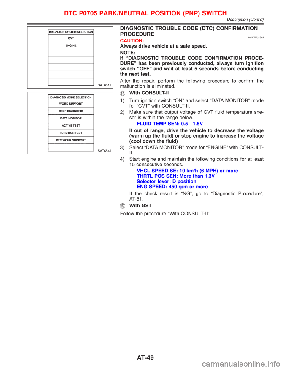
DIAGNOSTIC TROUBLE CODE (DTC) CONFIRMATION
PROCEDURE
NCAT0032S03CAUTION:
Always drive vehicle at a safe speed.
NOTE:
If ªDIAGNOSTIC TROUBLE CODE CONFIRMATION PROCE-
DUREº has been previously conducted, always turn ignition
switch ªOFFº and wait at least 5 seconds before conducting
the next test.
After the repair, perform the following procedure to confirm the
malfunction is eliminated.
With CONSULT-II
1) Turn ignition switch ªONº and select ªDATA MONITORº mode
for ªCVTº with CONSULT-II.
2) Make sure that output voltage of CVT fluid temperature sne-
sor is within the range below.
FLUID TEMP SEN: 0.5 - 1.5V
If out of range, drive the vehicle to decrease the voltage
(warm up the fluid) or stop engine to increase the voltage
(cool down the fluid)
3) Select ªDATA MONITORº mode for ªENGINEº with CONSULT-
II.
4) Start engine and maintain the following conditions for at least
15 consecutive seconds.
VHCL SPEED SE: 10 km/h (6 MPH) or more
THRTL POS SEN: More than 1.3V
Selector lever: D position
ENG SPEED: 450 rpm or more
If the check result is ªNGº, go to ªDiagnostic Procedureº,
AT-51.
With GST
Follow the procedure ªWith CONSULT-IIº.
SAT651J
SAT654J
DTC P0705 PARK/NEUTRAL POSITION (PNP) SWITCH
Description (Cont'd)
AT-49
Page 52 of 2267
Wiring Diagram Ð AT Ð PNP/SWNCAT0199
YAT251
DTC P0705 PARK/NEUTRAL POSITION (PNP) SWITCH
Wiring Diagram Ð AT Ð PNP/SW
AT-50