dtc 34 NISSAN PRIMERA 1999 Electronic Workshop Manual
[x] Cancel search | Manufacturer: NISSAN, Model Year: 1999, Model line: PRIMERA, Model: NISSAN PRIMERA 1999Pages: 2267, PDF Size: 35.74 MB
Page 83 of 2267

Wiring Diagram Ð AT Ð TPSNCAT0212
YAT252
DTC P1705 THROTTLE POSITION SENSOR
Wiring Diagram Ð AT Ð TPS
AT-81
Page 84 of 2267
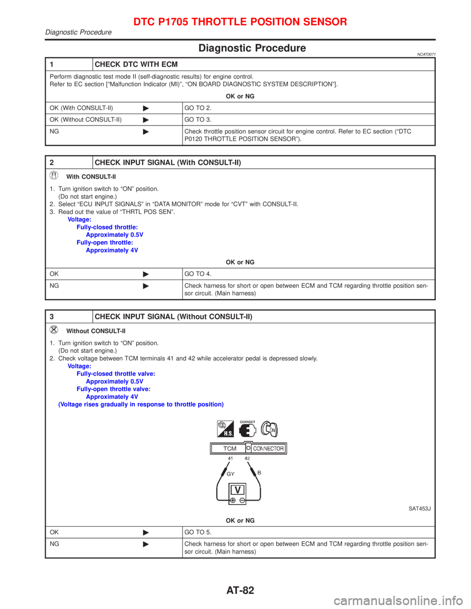
Diagnostic ProcedureNCAT0071
1 CHECK DTC WITH ECM
Perform diagnostic test mode II (self-diagnostic results) for engine control.
Refer to EC section [ªMalfunction Indicator (MI)º, ªON BOARD DIAGNOSTIC SYSTEM DESCRIPTIONº].
OK or NG
OK (With CONSULT-II)©GO TO 2.
OK (Without CONSULT-II)©GO TO 3.
NG©Check throttle position sensor circuit for engine control. Refer to EC section (ªDTC
P0120 THROTTLE POSITION SENSORº).
2 CHECK INPUT SIGNAL (With CONSULT-II)
With CONSULT-II
1. Turn ignition switch to ªONº position.
(Do not start engine.)
2. Select ªECU INPUT SIGNALSº in ªDATA MONITORº mode for ªCVTº with CONSULT-II.
3. Read out the value of ªTHRTL POS SENº.
Voltage:
Fully-closed throttle:
Approximately 0.5V
Fully-open throttle:
Approximately 4V
OK or NG
OK©GO TO 4.
NG©Check harness for short or open between ECM and TCM regarding throttle position sen-
sor circuit. (Main harness)
3 CHECK INPUT SIGNAL (Without CONSULT-II)
Without CONSULT-II
1. Turn ignition switch to ªONº position.
(Do not start engine.)
2. Check voltage between TCM terminals 41 and 42 while accelerator pedal is depressed slowly.
Voltage:
Fully-closed throttle valve:
Approximately 0.5V
Fully-open throttle valve:
Approximately 4V
(Voltage rises gradually in response to throttle position)
SAT453J
OK or NG
OK©GO TO 5.
NG©Check harness for short or open between ECM and TCM regarding throttle position sen-
sor circuit. (Main harness)
DTC P1705 THROTTLE POSITION SENSOR
Diagnostic Procedure
AT-82
Page 85 of 2267

4 CHECK THROTTLE POSITION SWITCH CIRCUIT (With CONSULT-II)
With CONSULT-II
1. Turn ignition switch to ªONº position.
(Do not start engine.)
2. Select ªECU INPUT SIGNALSº in ªDATA MONITORº mode for ªCVTº with CONSULT-II.
3. Read out ªCLOSED THL/SWº and ªW/O THRL/P-SWº depressing and releasing accelerator pedal.
Check the signal of throttle position switch is indicated properly.
OK or NG
OK©GO TO 6.
NG©Check the following items:
IThrottle position switch Ð Refer to ªComponents Inspectionº, AT-85.
IHarness for short or open between ignition switch and throttle position switch (Main
harness)
IHarness for short or open between throttle position switch and TCM (Main harness)
Accelerator pedal
conditionData monitor
CLOSED THL/SW W/O THRL/P-SW
ReleasedON OFF
Fully depressedOFF ON
MTLB0011
DTC P1705 THROTTLE POSITION SENSOR
Diagnostic Procedure (Cont'd)
AT-83
Page 86 of 2267
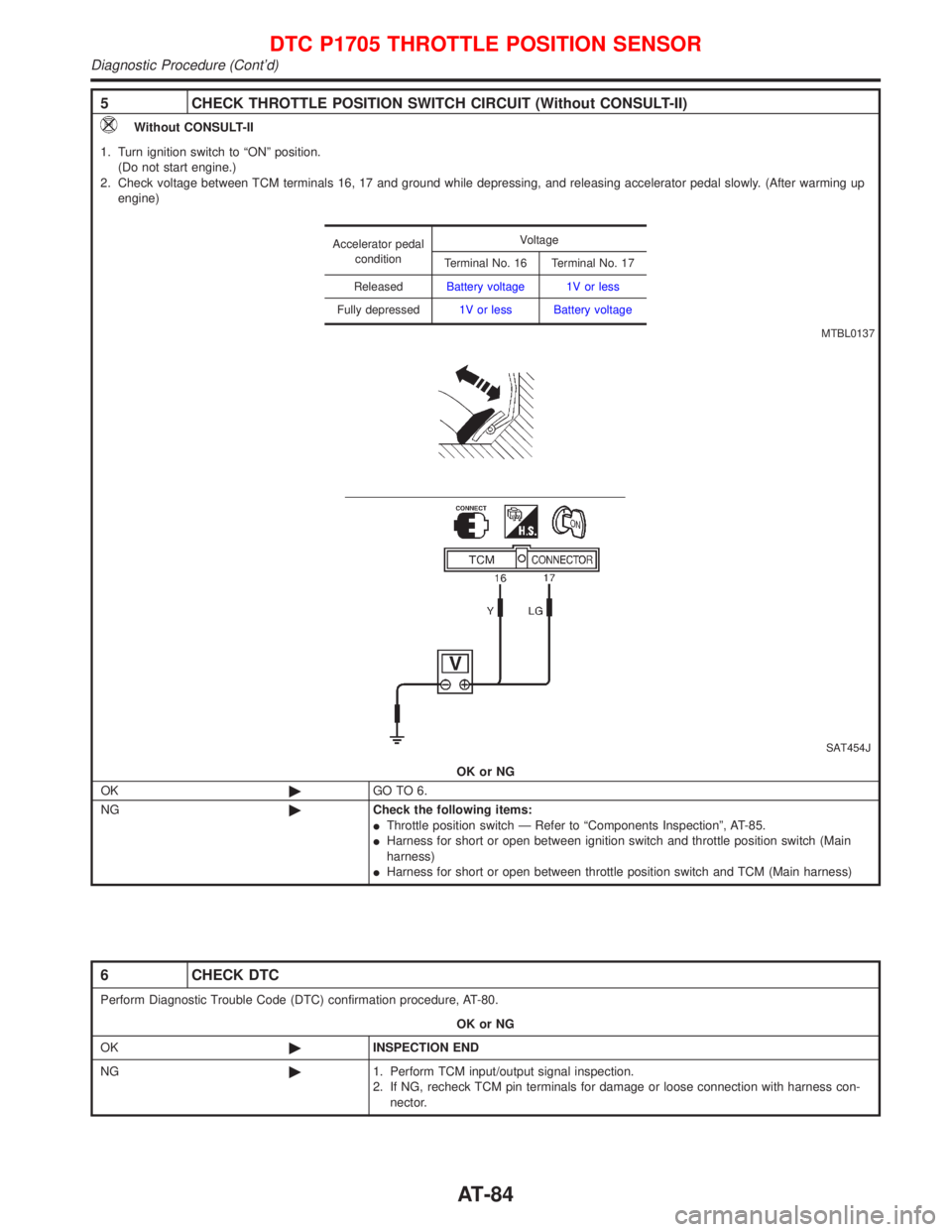
5 CHECK THROTTLE POSITION SWITCH CIRCUIT (Without CONSULT-II)
Without CONSULT-II
1. Turn ignition switch to ªONº position.
(Do not start engine.)
2. Check voltage between TCM terminals 16, 17 and ground while depressing, and releasing accelerator pedal slowly. (After warming up
engine)
SAT454J
OK or NG
OK©GO TO 6.
NG©Check the following items:
IThrottle position switch Ð Refer to ªComponents Inspectionº, AT-85.
IHarness for short or open between ignition switch and throttle position switch (Main
harness)
IHarness for short or open between throttle position switch and TCM (Main harness)
Accelerator pedal
conditionVoltage
Terminal No. 16 Terminal No. 17
ReleasedBattery voltage 1V or less
Fully depressed1V or less Battery voltage
MTBL0137
6 CHECK DTC
Perform Diagnostic Trouble Code (DTC) confirmation procedure, AT-80.
OK or NG
OK©INSPECTION END
NG©1. Perform TCM input/output signal inspection.
2. If NG, recheck TCM pin terminals for damage or loose connection with harness con-
nector.
DTC P1705 THROTTLE POSITION SENSOR
Diagnostic Procedure (Cont'd)
AT-84
Page 87 of 2267
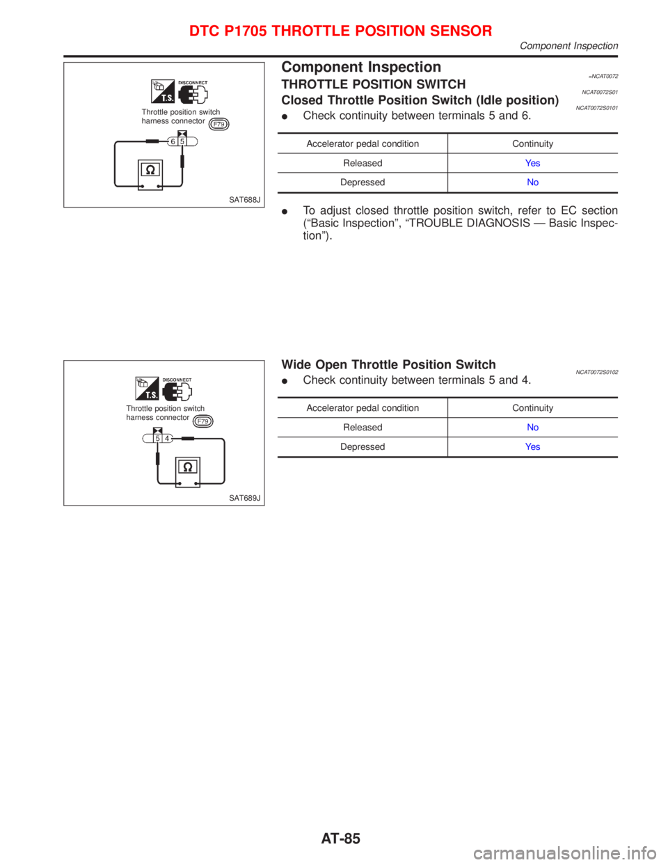
Component Inspection=NCAT0072THROTTLE POSITION SWITCHNCAT0072S01Closed Throttle Position Switch (Idle position)NCAT0072S0101ICheck continuity between terminals 5 and 6.
Accelerator pedal condition Continuity
ReleasedYe s
DepressedNo
ITo adjust closed throttle position switch, refer to EC section
(ªBasic Inspectionº, ªTROUBLE DIAGNOSIS Ð Basic Inspec-
tionº).
Wide Open Throttle Position SwitchNCAT0072S0102ICheck continuity between terminals 5 and 4.
Accelerator pedal condition Continuity
ReleasedNo
DepressedYe s
SAT688J Throttle position switch
harness connector
SAT689J Throttle position switch
harness connector
DTC P1705 THROTTLE POSITION SENSOR
Component Inspection
AT-85
Page 88 of 2267
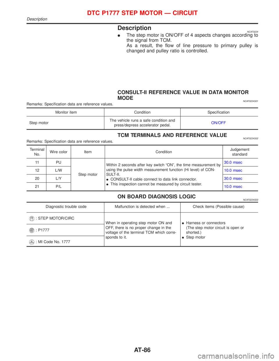
DescriptionNCAT0224IThe step motor is ON/OFF of 4 aspects changes according to
the signal from TCM.
As a result, the flow of line pressure to primary pulley is
changed and pulley ratio is controlled.
CONSULT-II REFERENCE VALUE IN DATA MONITOR
MODE
NCAT0224S01Remarks: Specification data are reference values.
Monitor item Condition Specification
Step motorThe vehicle runs a safe condition and
press/depress accelerator pedal.ON/OFF
TCM TERMINALS AND REFERENCE VALUENCAT0224S02Remarks: Specification data are reference values.
Terminal
No.Wire color Item ConditionJudgement
standard
11 P U
Step motorWithin 2 seconds after key switch ªONº, the time measurement by
using the pulse width measurement function (Hi level) of CON-
SULT-II.
ICONSULT-II cable connect to data link connector.
IThis inspection cannot be measured by circuit tester.30.0 msec
12 L/W10.0 msec
20 L/Y30.0 msec
21 P/L10.0 msec
ON BOARD DIAGNOSIS LOGICNCAT0224S03
Diagnostic trouble code Malfunction is detected when ... Check items (Possible cause)
: STEP MOTOR/CIRC
When in operating step motor ON and
OFF, there is no proper change in the
voltage of the terminal TCM which corre-
sponds to it.IHarness or connectors
(The step motor circuit is open or
shorted.)
IStep motor
: P1777
: MI Code No. 1777
DTC P1777 STEP MOTOR Ð CIRCUIT
Description
AT-86
Page 89 of 2267

DIAGNOSTIC TROUBLE CODE (DTC) CONFIRMATION
PROCEDURE
NCAT0224S04CAUTION:
IAlways drive vehicle at a safe speed.
IBe careful not to rev engine into the red zone on the
tachometer.
NOTE:
If ªDIAGNOSTIC TROUBLE CODE CONFIRMATION PROCE-
DUREº has been previously conducted, always turn ignition
switch ªOFFº and wait at least 5 seconds before conducting
the next test.
After the repair, perform the following procedure to confirm the
malfunction is eliminated.
With CONSULT-II
1) Turn ignition switch ªONº and select ªDATA MONITORº mode
for ªENGINEº with CONSULT-II.
2) Drive vehicle for at least 5 consecutive seconds.
If the check result is ªNGº, go to ªDiagnostic Procedureº,
AT-89.
With GST
Follow the procedure ªWith CONSULT-IIº.
SAT651J
SAT654J
DTC P1777 STEP MOTOR Ð CIRCUIT
Description (Cont'd)
AT-87
Page 90 of 2267
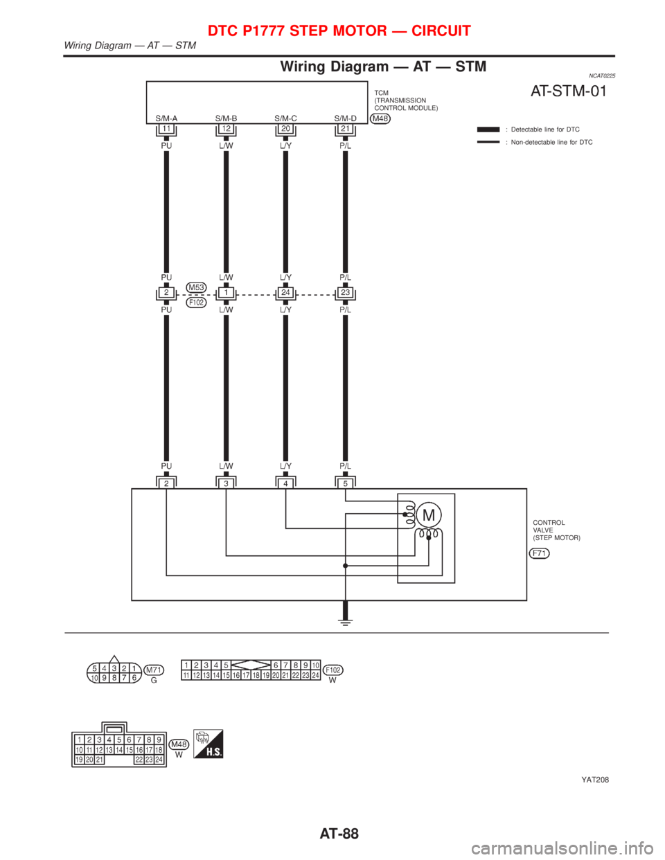
Wiring Diagram Ð AT Ð STMNCAT0225
YAT208
TCM
(TRANSMISSION
CONTROL MODULE)
: Detectable line for DTC
: Non-detectable line for DTC
CONTROL
VA LV E
(STEP MOTOR)
DTC P1777 STEP MOTOR Ð CIRCUIT
Wiring Diagram Ð AT Ð STM
AT-88
Page 91 of 2267
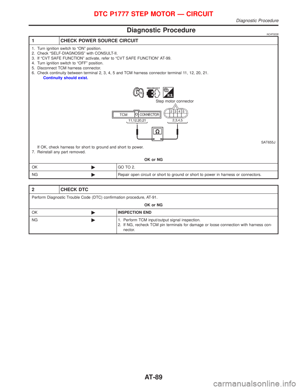
Diagnostic ProcedureNCAT0226
1 CHECK POWER SOURCE CIRCUIT
1. Turn ignition switch to ªONº position.
2. Check ªSELF-DIAGNOSISº with CONSULT-II.
3. If ªCVT SAFE FUNCTIONº activate, refer to ªCVT SAFE FUNCTIONº AT-99.
4. Turn ignition switch to ªOFFº position.
5. Disconnect TCM harness connector.
6. Check continuity between terminal 2, 3, 4, 5 and TCM harness connector terminal 11, 12, 20, 21.
Continuity should exist.
SAT655J
Step motor connector
If OK, check harness for short to ground and short to power.
7. Reinstall any part removed.
OK or NG
OK©GO TO 2.
NG©Repair open circuit or short to ground or short to power in harness or connectors.
2 CHECK DTC
Perform Diagnostic Trouble Code (DTC) confirmation procedure, AT-91.
OK or NG
OK©INSPECTION END
NG©1. Perform TCM input/output signal inspection.
2. If NG, recheck TCM pin terminals for damage or loose connection with harness con-
nector.
DTC P1777 STEP MOTOR Ð CIRCUIT
Diagnostic Procedure
AT-89
Page 92 of 2267
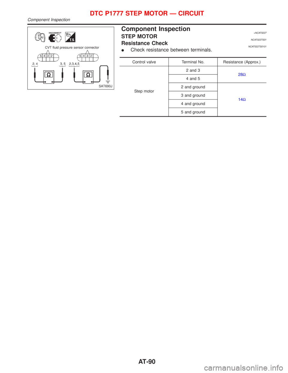
Component Inspection=NCAT0227STEP MOTORNCAT0227S01Resistance CheckNCAT0227S0101ICheck resistance between terminals.
Control valve Terminal No. Resistance (Approx.)
Step motor2 and 3
28W
4 and 5
2 and ground
14W 3 and ground
4 and ground
5 and ground
SAT690J CVT fluid pressure sensor connector
DTC P1777 STEP MOTOR Ð CIRCUIT
Component Inspection
AT-90