engine oil NISSAN PRIMERA 1999 Electronic User Guide
[x] Cancel search | Manufacturer: NISSAN, Model Year: 1999, Model line: PRIMERA, Model: NISSAN PRIMERA 1999Pages: 2267, PDF Size: 35.74 MB
Page 299 of 2267
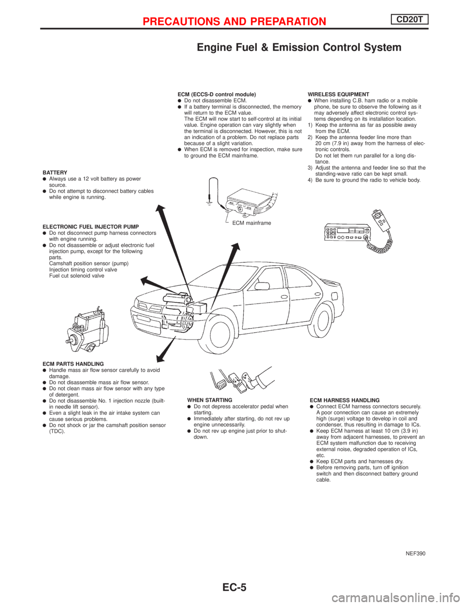
Engine Fuel & Emission Control System
NEF390 ECM (ECCS-D control module)
lDo not disassemble ECM.lIf a battery terminal is disconnected, the memory
will return to the ECM value.
The ECM will now start to self-control at its initial
value. Engine operation can vary slightly when
the terminal is disconnected. However, this is not
an indication of a problem. Do not replace parts
because of a slight variation.
lWhen ECM is removed for inspection, make sure
to ground the ECM mainframe.WIRELESS EQUIPMENT
lWhen installing C.B. ham radio or a mobile
phone, be sure to observe the following as it
may adversely affect electronic control sys-
tems depending on its installation location.
1) Keep the antenna as far as possible away
from the ECM.
2) Keep the antenna feeder line more than
20 cm (7.9 in) away from the harness of elec-
tronic controls.
Do not let them run parallel for a long dis-
tance.
3) Adjust the antenna and feeder line so that the
standing-wave ratio can be kept small.
4) Be sure to ground the radio to vehicle body.
ECM HARNESS HANDLING
lConnect ECM harness connectors securely.
A poor connection can cause an extremely
high (surge) voltage to develop in coil and
condenser, thus resulting in damage to ICs.
lKeep ECM harness at least 10 cm (3.9 in)
away from adjacent harnesses, to prevent an
ECM system malfunction due to receiving
external noise, degraded operation of ICs,
etc.
lKeep ECM parts and harnesses dry.lBefore removing parts, turn off ignition
switch and then disconnect battery ground
cable. WHEN STARTING
lDo not depress accelerator pedal when
starting.
lImmediately after starting, do not rev up
engine unnecessarily.
lDo not rev up engine just prior to shut-
down. ECM PARTS HANDLING
lHandle mass air flow sensor carefully to avoid
damage.
lDo not disassemble mass air flow sensor.lDo not clean mass air flow sensor with any type
of detergent.
lDo not disassemble No. 1 injection nozzle (built-
in needle lift sensor).
lEven a slight leak in the air intake system can
cause serious problems.
lDo not shock or jar the camshaft position sensor
(TDC). ELECTRONIC FUEL INJECTOR PUMP
lDo not disconnect pump harness connectors
with engine running.
lDo not disassemble or adjust electronic fuel
injection pump, except for the following
parts.
Camshaft position sensor (pump)
Injection timing control valve
Fuel cut solenoid valve BATTERY
lAlways use a 12 volt battery as power
source.
lDo not attempt to disconnect battery cables
while engine is running.
ECM mainframe
PRECAUTIONS AND PREPARATIONCD20T
EC-5
Page 341 of 2267
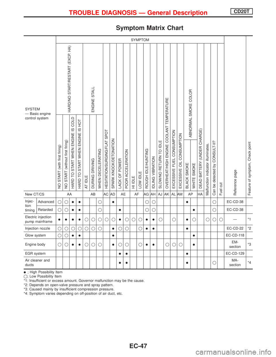
Symptom Matrix Chart
SYSTEM
Ð Basic engine
control systemSYMPTOM
Reference page
Feature of symptom, Check pointHARD/NO START/RESTART (EXCP. HA)
ENGINE STALL
HESITATION/SURGING/FLAT SPOT
SPARK KNOCK/DETONATION
LACK OF POWER
POOR ACCELERATION
HI IDLE
LOW IDLE
ROUGH IDLE/HUNTING
IDLING VIBRATION
SLOW/NO RETURN TO IDLE
OVERHEAT/HIGH ENGINE COOLANT TEMPERATURE
EXCESSIVE FUEL CONSUMPTION
EXCESSIVE OIL CONSUMPTION
ABNORMAL SMOKE COLOR
DEAD BATTERY (UNDER CHARGE)
Malfunction indicator illuminates.
Can be detected by CONSULT-II?
Fuel cutNO START (with first firing)
NO START (without first firing)
HARD TO START WHEN ENGINE IS COLD
HARD TO START WHEN ENGINE IS HOT
AT IDLE
DURING DRIVING
WHEN DECELERATING
BLACK SMOKE
WHITE SMOKENew CT/CS AA AB AC AD AE AF AG AH AJ AK AL AM AP HA
Injec-
tion
timingAdvancedqq
llqlqqlqEC-CD-38
Retardedqq
llqlqqlqEC-CD-38
Electric injection
pump mainframe
llllqqqqqlqqqllqqlq qqqÐ*1
Injection nozzleqqqqqqq
lqq qll lEC-CD-22 *2
Glow systemqq
ll l lEC-CD-118
Engine bodyqq
llqqqlqq qllqqqlEM-
section*3
EGR system
ll lEC-CD-129
Air cleaner and
ducts
ll lqMA-
section*4
l; High Possibility Item
q; Low Possibility Item
*1: Insufficient or excess amount. Governor malfunction may be the cause.
*2: Depends on open-valve pressure and spray pattern.
*3: Caused mainly by insufficient compression pressure.
*4: Symptom varies depending on off-position of air duct, etc.
TROUBLE DIAGNOSIS Ð General DescriptionCD20T
EC-47
Page 342 of 2267
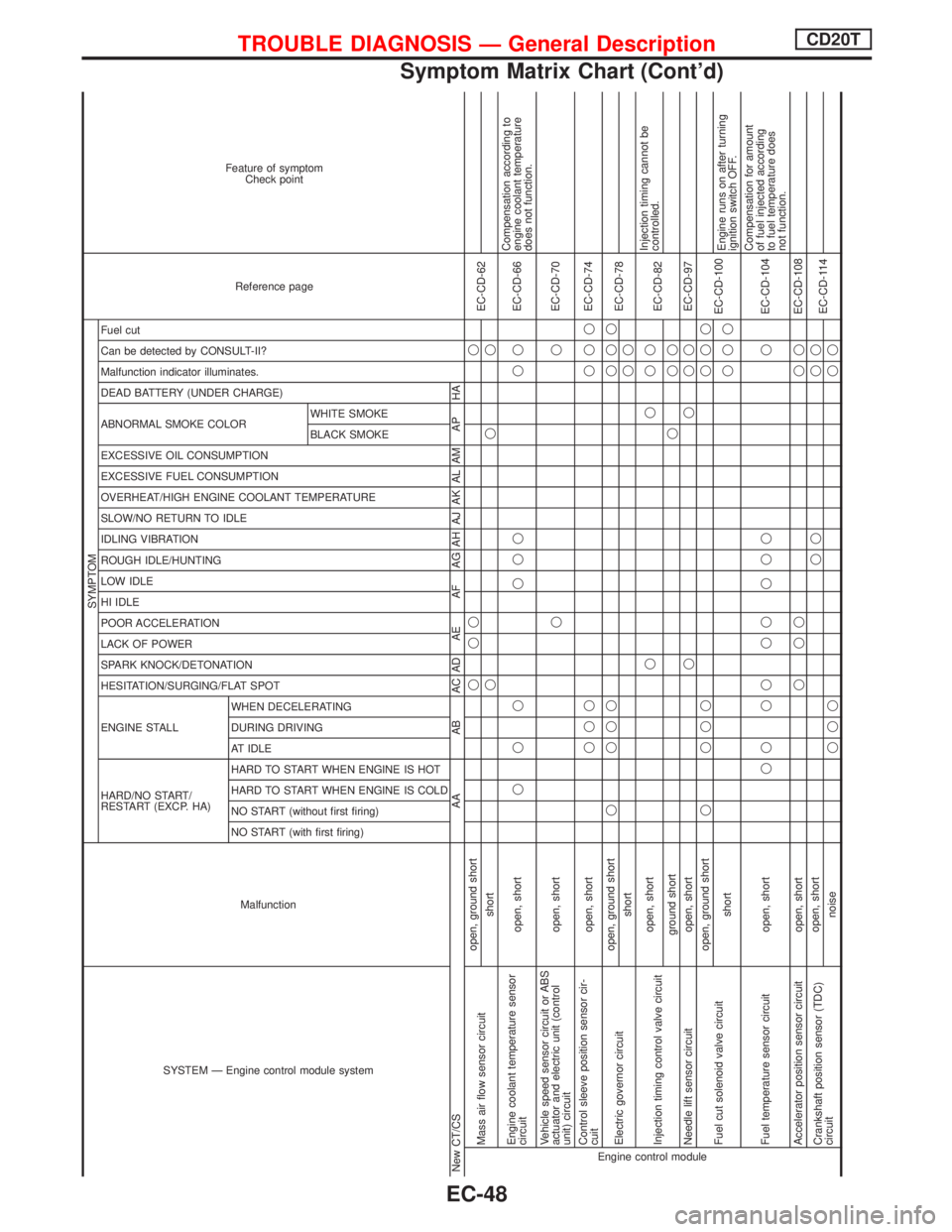
SYSTEM Ð Engine control module systemMalfunction
SYMPTOM
Reference page Feature of symptom
Check point
HARD/NO START/
RESTART (EXCP. HA) ENGINE STALL HESITATION/SURGING/FLAT SPOT SPARK KNOCK/DETONATION
LACK OF POWER
POOR ACCELERATION
HI IDLE
LOW IDLE
ROUGH IDLE/HUNTING
IDLING VIBRATION
SLOW/NO RETURN TO IDLE
OVERHEAT/HIGH ENGINE COOLANT TEMPERATURE
EXCESSIVE FUEL CONSUMPTION
EXCESSIVE OIL CONSUMPTION ABNORMAL SMOKE COLOR
DEAD BATTERY (UNDER CHARGE) Malfunction indicator illuminates.
Can be detected by CONSULT-II?
Fuel cut
NO START (with first firing) NO START (without first firing)
HARD TO START WHEN ENGINE IS COLD
HARD TO START WHEN ENGINE IS HOT
AT IDLE
DURING DRIVING
WHEN DECELERATINGBLACK SMOKE WHITE SMOKE
New CT/CS AA AB AC AD AE AF AG AH AJ AK AL AM AP HAEngine control moduleMass air flow sensor circuitopen, ground shortqqq q
EC-CD-62
shortqqq
Engine coolant temperature sensor
circuitopen, shortqqq qqq qqEC-CD-66Compensation according to
engine coolant temperature
does not function.
Vehicle speed sensor circuit or ABS
actuator and electric unit (control
unit) circuitopen, shortqqEC-CD-70
Control sleeve position sensor cir-
cuitopen, shortqqq qqqEC-CD-74
Electric governor circuitopen, ground shortq qqq qqq
EC-CD-78
shortqq
Injection timing control valve circuitopen, shortqqqq
EC-CD-82Injection timing cannot be
controlled.
ground shortqqq
Needle lift sensor circuit open, shortqqqqEC-CD-97
Fuel cut solenoid valve circuitopen, ground shortq qqq qqq
EC-CD-100
shortqqqEngine runs on after turning
ignition switch OFF.
Fuel temperature sensor circuit open, shortqq qq qq q qq qEC-CD-104Compensation for amount
of fuel injected according
to fuel temperature does
not function.
Accelerator position sensor circuit open, shortqqq qqEC-CD-108
Crankshaft position sensor (TDC)
circuitopen, shortqq qq
EC-CD-114
noiseqqq qq
TROUBLE DIAGNOSIS Ð General DescriptionCD20T
Symptom Matrix Chart (Cont'd)
EC-48
Page 343 of 2267
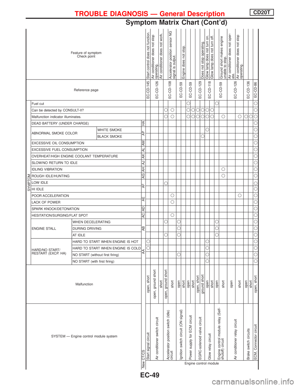
SYSTEM Ð Engine control module systemMalfunction
SYMPTOM
Reference page Feature of symptom
Check point
HARD/NO START/
RESTART (EXCP. HA) ENGINE STALL HESITATION/SURGING/FLAT SPOT SPARK KNOCK/DETONATION
LACK OF POWER
POOR ACCELERATION
HI IDLE
LOW IDLE
ROUGH IDLE/HUNTING
IDLING VIBRATION
SLOW/NO RETURN TO IDLE
OVERHEAT/HIGH ENGINE COOLANT TEMPERATURE
EXCESSIVE FUEL CONSUMPTION
EXCESSIVE OIL CONSUMPTION ABNORMAL SMOKE COLOR
DEAD BATTERY (UNDER CHARGE) Malfunction indicator illuminates.
Can be detected by CONSULT-II?
Fuel cut
NO START (with first firing) NO START (without first firing)
HARD TO START WHEN ENGINE IS COLD
HARD TO START WHEN ENGINE IS HOT
AT IDLE
DURING DRIVING
WHEN DECELERATINGBLACK SMOKE WHITE SMOKE
New CT/CS AA AB AC AD AE AF AG AH AJ AK AL AM AP HAEngine control moduleStart signal circuit open, shortqqEC-CD-145 Start control does not function.
Air conditioner switch circuitopen, ground short
EC-CD-126Air conditioner does not stop
operating.
shortAir conditioner does not work.
Accelerator position switch (Idle)
circuitopen, ground shortqq q qq
EC-CD-108
shortqqq qqAccelerator position sensor NG
signal is output.
Ignition switch circuit (ON signal)openq qqq
EC-CD-59
shortEngine does not stop.
Power supply for ECM circuitopenqqq
EC-CD-59
shortqq
EGRC-solenoid valve circuitopen, shortqq
EC-CD-129
ground shortqqqDoes not stop operating.
Glow relay circuitopenqqqq q qq
EC-CD-118Glow lamp does not turn on.
shortqqGlow lamp does not turn off.
Engine control module relay (Self-
shutoff) circuitopenqqqq
EC-CD-59
shortqq qGround short makes engine
unable to stop.
Air conditioner relay circuitopen
EC-CD-126Air conditioner does not oper-
ate.
shortqqAir conditioner does not stop
operating.
Brake switch circuitsopenq
EC-CD-136
shortq
ECM, Connector circuit open, shortqqqqqqqqqqqqq qqqqqqqqqqqqEC-CD-86
TROUBLE DIAGNOSIS Ð General DescriptionCD20T
Symptom Matrix Chart (Cont'd)
EC-49
Page 368 of 2267

Control Sleeve Position Sensor (CSPS)
The control sleeve position sensor is installed on the electric
governor. It senses the position of control sleeve (rotor angle)
while the control sleeve is being driven by the electric governor,
and feeds it back to the ECM.
Malfunction is detected when ....Check Items
(Possible cause)
lAn excessively high or low voltage from the sensor is
detected by ECM.
...............................................................................................
lAn incorrect voltage signal from the sensor is detected by
ECM during engine running.
lHarness or connectors
(The control sleeve position sensor circuit is open or
shorted.)
lControl sleeve position sensor
DIAGNOSTIC TROUBLE CONFIRMATION
PROCEDURE
1) Turn ignition switch to ªONº position and select ªDATA
MONITORº mode with CONSULT-II.
2) Start engine and run it for at least 2 seconds at idle
speed.
SEF641S Shaft
Sensor coil
NEF796
.Electronic injection pump
harness connector (control
sleeve position sensor)
TROUBLE DIAGNOSIS 4CD20T
EC-74
Page 372 of 2267
Electric Governor
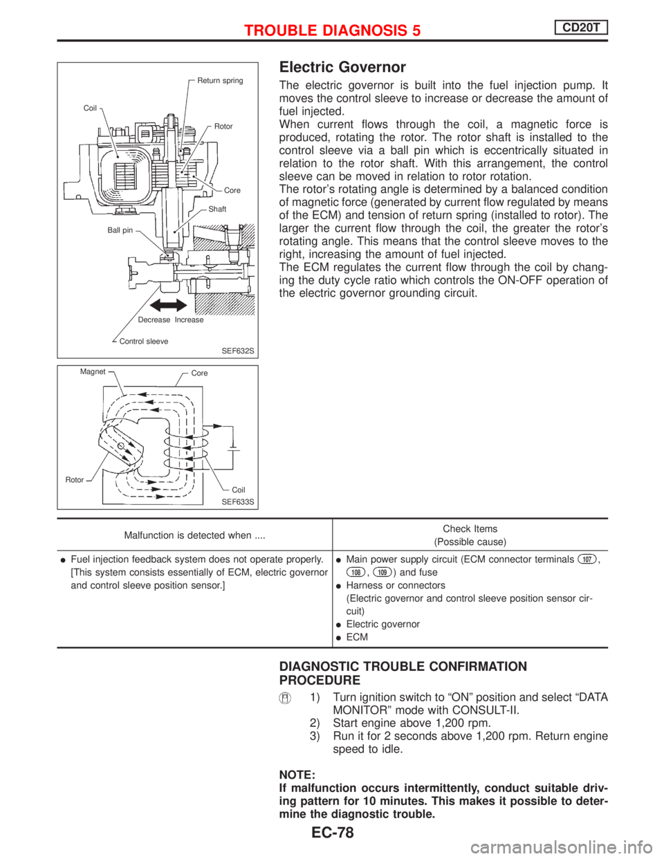
The electric governor is built into the fuel injection pump. It
moves the control sleeve to increase or decrease the amount of
fuel injected.
When current flows through the coil, a magnetic force is
produced, rotating the rotor. The rotor shaft is installed to the
control sleeve via a ball pin which is eccentrically situated in
relation to the rotor shaft. With this arrangement, the control
sleeve can be moved in relation to rotor rotation.
The rotor's rotating angle is determined by a balanced condition
of magnetic force (generated by current flow regulated by means
of the ECM) and tension of return spring (installed to rotor). The
larger the current flow through the coil, the greater the rotor's
rotating angle. This means that the control sleeve moves to the
right, increasing the amount of fuel injected.
The ECM regulates the current flow through the coil by chang-
ing the duty cycle ratio which controls the ON-OFF operation of
the electric governor grounding circuit.
Malfunction is detected when ....Check Items
(Possible cause)
lFuel injection feedback system does not operate properly.
[This system consists essentially of ECM, electric governor
and control sleeve position sensor.]lMain power supply circuit (ECM connector terminals107,
108,109) and fuse
lHarness or connectors
(Electric governor and control sleeve position sensor cir-
cuit)
lElectric governor
lECM
DIAGNOSTIC TROUBLE CONFIRMATION
PROCEDURE
1) Turn ignition switch to ªONº position and select ªDATA
MONITORº mode with CONSULT-II.
2) Start engine above 1,200 rpm.
3) Run it for 2 seconds above 1,200 rpm. Return engine
speed to idle.
NOTE:
If malfunction occurs intermittently, conduct suitable driv-
ing pattern for 10 minutes. This makes it possible to deter-
mine the diagnostic trouble.
SEF632S Return spring
Coil
Rotor
Core
Shaft
Ball pin
Decrease Increase
Control sleeve
SEF633S Magnet
Core
Rotor
Coil
TROUBLE DIAGNOSIS 5CD20T
EC-78
Page 381 of 2267
Cooling Fan (Overheat)
SYSTEM DESCRIPTION
Vehicle speed sensorEVehicle speed
ECM
ECooling
fan
relay(s)Engine coolant temperature sensorEEngine coolant temperature
Air conditioner switch
EAir conditioner ªONº signal
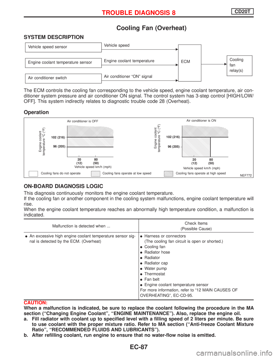
The ECM controls the cooling fan corresponding to the vehicle speed, engine coolant temperature, air con-
ditioner system pressure and air conditioner ON signal. The control system has 3-step control [HIGH/LOW/
OFF]. This system indirectly relates to diagnostic trouble code 28 (Overheat).
Operation
ON-BOARD DIAGNOSIS LOGIC
This diagnosis continuously monitors the engine coolant temperature.
If the cooling fan or another component in the cooling system malfunctions, engine coolant temperature will
rise.
When the engine coolant temperature reaches an abnormally high temperature condition, a malfunction is
indicated.
Malfunction is detected when ...Check Items
(Possible Cause)
lAn excessive high engine coolant temperature sensor sig-
nal is detected by the ECM. (Overheat)lHarness or connectors
(The cooling fan circuit is open or shorted.)
lCooling fan
lRadiator hose
lRadiator
lRadiator cap
lWater pump
lThermostat
lFan belt
lEngine coolant temperature sensor
For more information, refer to ª12 MAIN CAUSES OF
OVERHEATINGº, EC-CD-95.
CAUTION:
When a malfunction is indicated, be sure to replace the coolant following the procedure in the MA
section (ªChanging Engine Coolantº, ªENGINE MAINTENANCEº). Also, replace the engine oil.
a. Fill radiator with coolant up to specified level with a filling speed of 2 liters per minute. Be sure
to use coolant with the proper mixture ratio. Refer to MA section (ªAnti-freeze Coolant Mixture
Ratioº, ªRECOMMENDED FLUIDS AND LUBRICANTSº).
b. After refilling coolant, run engine to ensure that no water-flow noise is emitted.
NEF772
Engine coolant
temperature ÉC (ÉF)
Air conditioner is OFF
.102 (216)
.96 (205)
.20
(12).80
(50)
Vehicle speed km/h (mph)
Cooling fans do not operateCooling fans operate at high speed
Engine coolant
temperature ÉC (ÉF)
Vehicle speed km/h (mph)
.20
(12).80
(50)
.102 (216)
.96 (205)Air conditioner is ON
Cooling fans operate at low speed
TROUBLE DIAGNOSIS 8CD20T
EC-87
Page 388 of 2267
pB
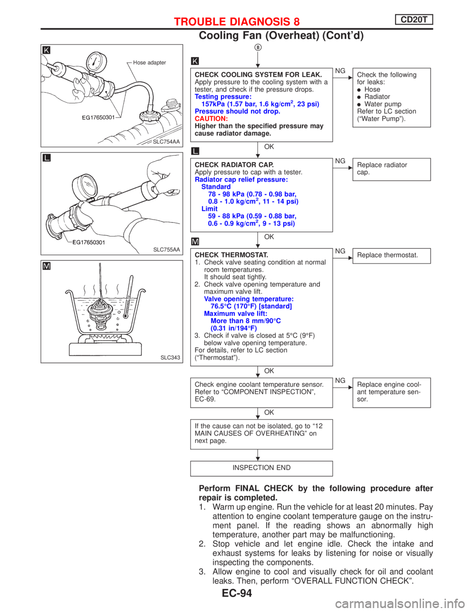
CHECK COOLING SYSTEM FOR LEAK.
Apply pressure to the cooling system with a
tester, and check if the pressure drops.
Testing pressure:
157kPa (1.57 bar, 1.6 kg/cm
2, 23 psi)
Pressure should not drop.
CAUTION:
Higher than the specified pressure may
cause radiator damage.
OK
ENG
Check the following
for leaks:
lHoselRadiatorlWater pump
Refer to LC section
(ªWater Pumpº).
CHECK RADIATOR CAP.
Apply pressure to cap with a tester.
Radiator cap relief pressure:
Standard
78 - 98 kPa (0.78 - 0.98 bar,
0.8 - 1.0 kg/cm
2, 11 - 14 psi)
Limit
59 - 88 kPa (0.59 - 0.88 bar,
0.6 - 0.9 kg/cm
2,9-13psi)
OK
ENG
Replace radiator
cap.
CHECK THERMOSTAT.
1. Check valve seating condition at normal
room temperatures.
It should seat tightly.
2. Check valve opening temperature and
maximum valve lift.
Valve opening temperature:
76.5ÉC (170ÉF) [standard]
Maximum valve lift:
More than 8 mm/90ÉC
(0.31 in/194ÉF)
3. Check if valve is closed at 5ÉC (9ÉF)
below valve opening temperature.
For details, refer to LC section
(ªThermostatº).
OK
ENG
Replace thermostat.
Check engine coolant temperature sensor.
Refer to ªCOMPONENT INSPECTIONº,
EC-69.
OK
ENG
Replace engine cool-
ant temperature sen-
sor.
If the cause can not be isolated, go to ª12
MAIN CAUSES OF OVERHEATINGº on
next page.
INSPECTION END
Perform FINAL CHECK by the following procedure after
repair is completed.
1. Warm up engine. Run the vehicle for at least 20 minutes. Pay
attention to engine coolant temperature gauge on the instru-
ment panel. If the reading shows an abnormally high
temperature, another part may be malfunctioning.
2. Stop vehicle and let engine idle. Check the intake and
exhaust systems for leaks by listening for noise or visually
inspecting the components.
3. Allow engine to cool and visually check for oil and coolant
leaks. Then, perform ªOVERALL FUNCTION CHECKº.
Hose adapter
.SLC754AA
SLC755AA
SLC343
H
H
H
H
H
H
TROUBLE DIAGNOSIS 8CD20T
Cooling Fan (Overheat) (Cont'd)
EC-94
Page 408 of 2267
Crankshaft Position Sensor (TDC)
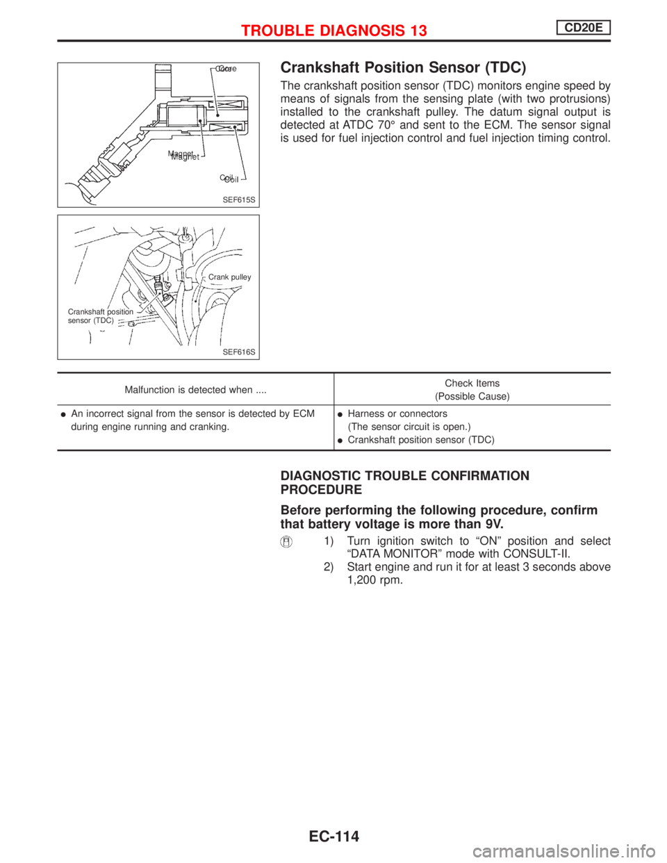
The crankshaft position sensor (TDC) monitors engine speed by
means of signals from the sensing plate (with two protrusions)
installed to the crankshaft pulley. The datum signal output is
detected at ATDC 70É and sent to the ECM. The sensor signal
is used for fuel injection control and fuel injection timing control.
Malfunction is detected when ....Check Items
(Possible Cause)
lAn incorrect signal from the sensor is detected by ECM
during engine running and cranking.lHarness or connectors
(The sensor circuit is open.)
lCrankshaft position sensor (TDC)
DIAGNOSTIC TROUBLE CONFIRMATION
PROCEDURE
Before performing the following procedure, confirm
that battery voltage is more than 9V.
1) Turn ignition switch to ªONº position and select
ªDATA MONITORº mode with CONSULT-II.
2) Start engine and run it for at least 3 seconds above
1,200 rpm.
SEF615S Core
Magnet
Coil
SEF616S Crank pulley
Crankshaft position
sensor (TDC)
TROUBLE DIAGNOSIS 13CD20E
EC-114
Page 418 of 2267
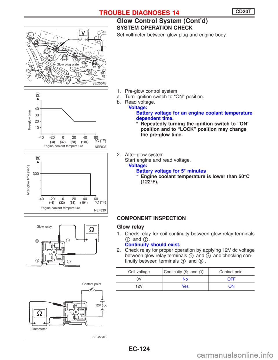
SYSTEM OPERATION CHECK
Set voltmeter between glow plug and engine body.
1. Pre-glow control system
a. Turn ignition switch to ªONº position.
b. Read voltage.
Voltage:
Battery voltage for an engine coolant temperature
dependent time.
* Repeatedly turning the ignition switch to ªONº
position and to ªLOCKº position may change
the pre-glow time.
2. After-glow system
Start engine and read voltage.
Voltage:
Battery voltage for 5* minutes
* Engine coolant temperature is lower than 50ÉC
(122ÉF).
COMPONENT INSPECTION
Glow relay
1. Check relay for coil continuity between glow relay terminals
p1andp2.
Continuity should exist.
2. Check relay for proper operation by applying 12V dc voltage
between glow relay terminals
p1andp2and checking con-
tinuity between terminals
p3andp5.
Coil voltage Continuityp3andp5Contact point
0VNo OFF
12VYe s O N
SEC554B Glow plug plate
NEF838
Pre-glow time
Engine coolant temperature
.(-4) (32) (68) (104)
NEF839 Engine coolant temperature
After glow time (sec.)
.(-4) (32) (68) (104)
SEC564B OhmmeterGlow relay
Contact point
12V dc
p2
p1
p3
p5
TROUBLE DIAGNOSES 14CD20T
Glow Control System (Cont'd)
EC-124