engine oil NISSAN PRIMERA 1999 Electronic Service Manual
[x] Cancel search | Manufacturer: NISSAN, Model Year: 1999, Model line: PRIMERA, Model: NISSAN PRIMERA 1999Pages: 2267, PDF Size: 35.74 MB
Page 716 of 2267
DescriptionNCEC0279SYSTEM DESCRIPTIONNCEC0279S01
Sensor Input Signal to ECMECM func-
tionActuator
Crankshaft position sensor (POS) Engine speed
Idle air con-
trolIACV-AAC valve Engine coolant temperature sensor Engine coolant temperature
Ignition switch Start signal
Throttle position sensor Throttle position
PNP switch Park/Neutral position
Air conditioner switch Air conditioner operation
Power steering oil pressure switch Power steering load signal
Battery Battery voltage
Vehicle speed sensor or ABS actuator and
electric unit (control unit)Vehicle speed
Cooling fan Cooling fan operation
Electrical load Electrical load signal
This system automatically controls engine idle speed to a specified
level. Idle speed is controlled through fine adjustment of the
amount of air which by-passes the throttle valve via IACV-AAC
valve. The IACV-AAC valve changes the opening of the air by-pass
passage to control the amount of auxiliary air. This valve is actu-
ated by a step motor built into the valve, which moves the valve in
the axial direction in steps corresponding to the ECM output sig-
nals. One step of IACV-AAC valve movement causes the respec-
tive opening of the air by-pass passage. (i.e. when the step
advances, the opening is enlarged.) The opening of the valve is
varied to allow for optimum control of the engine idling speed. The
crankshaft position sensor (POS) detects the actual engine speed
and sends a signal to the ECM. The ECM then controls the step
position of the IACV-AAC valve so that engine speed coincides with
the target value memorized in ECM. The target engine speed is the
lowest speed at which the engine can operate steadily. The opti-
mum value stored in the ECM is determined by taking into consid-
eration various engine conditions, such as during warm up,
deceleration, and engine load (air conditioner, power steering, cool-
ing fan operation and electrical load).
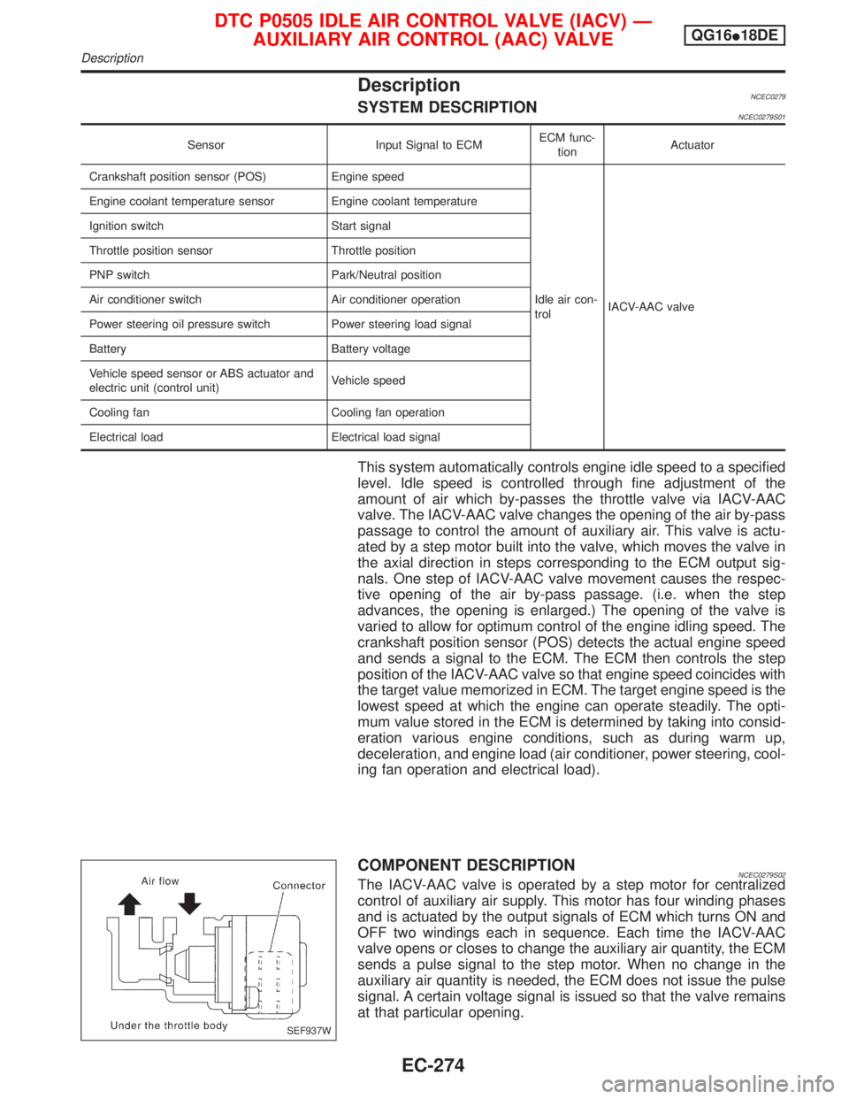
COMPONENT DESCRIPTIONNCEC0279S02The IACV-AAC valve is operated by a step motor for centralized
control of auxiliary air supply. This motor has four winding phases
and is actuated by the output signals of ECM which turns ON and
OFF two windings each in sequence. Each time the IACV-AAC
valve opens or closes to change the auxiliary air quantity, the ECM
sends a pulse signal to the step motor. When no change in the
auxiliary air quantity is needed, the ECM does not issue the pulse
signal. A certain voltage signal is issued so that the valve remains
at that particular opening.
SEF937W
DTC P0505 IDLE AIR CONTROL VALVE (IACV) Ð
AUXILIARY AIR CONTROL (AAC) VALVEQG16I18DE
Description
EC-274
Page 726 of 2267
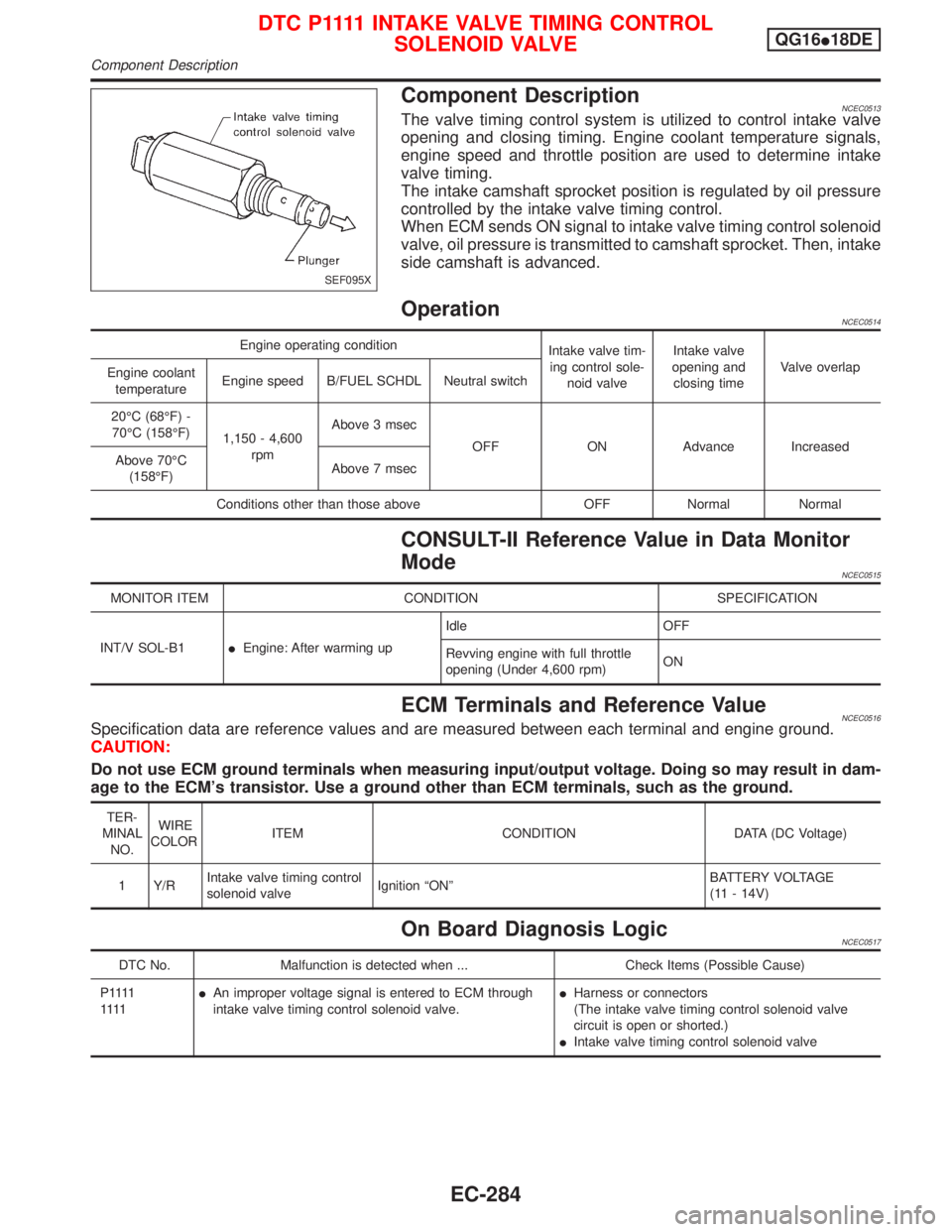
Component DescriptionNCEC0513The valve timing control system is utilized to control intake valve
opening and closing timing. Engine coolant temperature signals,
engine speed and throttle position are used to determine intake
valve timing.
The intake camshaft sprocket position is regulated by oil pressure
controlled by the intake valve timing control.
When ECM sends ON signal to intake valve timing control solenoid
valve, oil pressure is transmitted to camshaft sprocket. Then, intake
side camshaft is advanced.
OperationNCEC0514
Engine operating condition
Intake valve tim-
ing control sole-
noid valveIntake valve
opening and
closing timeValve overlap
Engine coolant
temperatureEngine speed B/FUEL SCHDL Neutral switch
20ÉC (68ÉF) -
70ÉC (158ÉF)
1,150 - 4,600
rpmAbove 3 msec
OFF ON Advance Increased
Above 70ÉC
(158ÉF)Above 7 msec
Conditions other than those above OFF Normal Normal
CONSULT-II Reference Value in Data Monitor
Mode
NCEC0515
MONITOR ITEM CONDITION SPECIFICATION
INT/V SOL-B1IEngine: After warming upIdle OFF
Revving engine with full throttle
opening (Under 4,600 rpm)ON
ECM Terminals and Reference ValueNCEC0516Specification data are reference values and are measured between each terminal and engine ground.
CAUTION:
Do not use ECM ground terminals when measuring input/output voltage. Doing so may result in dam-
age to the ECM's transistor. Use a ground other than ECM terminals, such as the ground.
TER-
MINAL
NO.WIRE
COLORITEM CONDITION DATA (DC Voltage)
1 Y/RIntake valve timing control
solenoid valveIgnition ªONºBATTERY VOLTAGE
(11 - 14V)
On Board Diagnosis LogicNCEC0517
DTC No. Malfunction is detected when ... Check Items (Possible Cause)
P 1111
1111IAn improper voltage signal is entered to ECM through
intake valve timing control solenoid valve.IHarness or connectors
(The intake valve timing control solenoid valve
circuit is open or shorted.)
IIntake valve timing control solenoid valve
SEF095X
D T C P 1111 I N TA K E VA LV ETIMING CONTROL
SOLENOID VALVEQG16I18DE
Component Description
EC-284
Page 732 of 2267
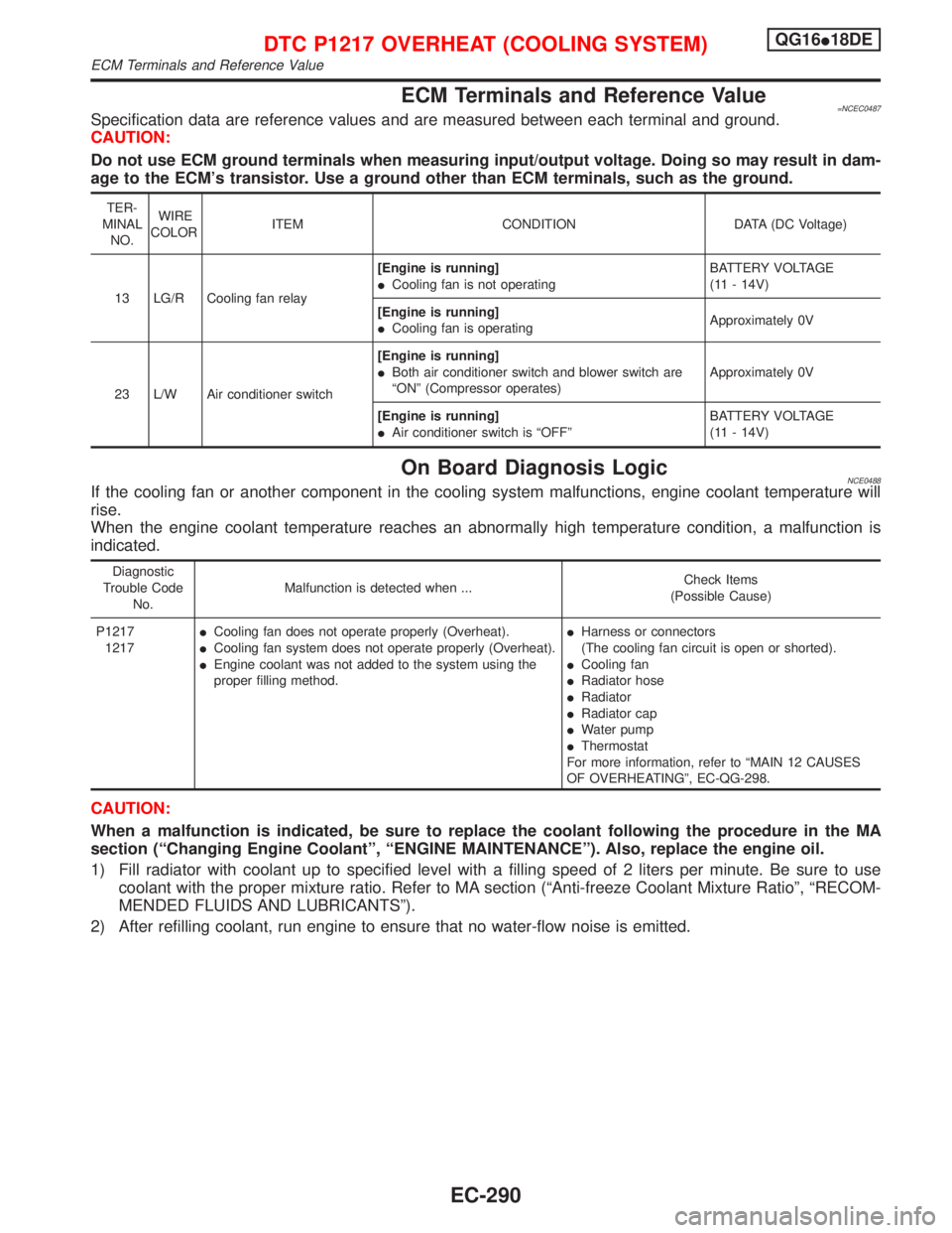
ECM Terminals and Reference Value=NCEC0487Specification data are reference values and are measured between each terminal and ground.
CAUTION:
Do not use ECM ground terminals when measuring input/output voltage. Doing so may result in dam-
age to the ECM's transistor. Use a ground other than ECM terminals, such as the ground.
TER-
MINAL
NO.WIRE
COLORITEM CONDITION DATA (DC Voltage)
13 LG/R Cooling fan relay[Engine is running]
ICooling fan is not operatingBATTERY VOLTAGE
(11 - 14V)
[Engine is running]
ICooling fan is operatingApproximately 0V
23 L/W Air conditioner switch[Engine is running]
IBoth air conditioner switch and blower switch are
ªONº (Compressor operates)Approximately 0V
[Engine is running]
IAir conditioner switch is ªOFFºBATTERY VOLTAGE
(11 - 14V)
On Board Diagnosis LogicNCE0488If the cooling fan or another component in the cooling system malfunctions, engine coolant temperature will
rise.
When the engine coolant temperature reaches an abnormally high temperature condition, a malfunction is
indicated.
Diagnostic
Trouble Code
No.Malfunction is detected when ...Check Items
(Possible Cause)
P1217
1217ICooling fan does not operate properly (Overheat).
ICooling fan system does not operate properly (Overheat).
IEngine coolant was not added to the system using the
proper filling method.IHarness or connectors
(The cooling fan circuit is open or shorted).
ICooling fan
IRadiator hose
IRadiator
IRadiator cap
IWater pump
IThermostat
For more information, refer to ªMAIN 12 CAUSES
OF OVERHEATINGº, EC-QG-298.
CAUTION:
When a malfunction is indicated, be sure to replace the coolant following the procedure in the MA
section (ªChanging Engine Coolantº, ªENGINE MAINTENANCEº). Also, replace the engine oil.
1) Fill radiator with coolant up to specified level with a filling speed of 2 liters per minute. Be sure to use
coolant with the proper mixture ratio. Refer to MA section (ªAnti-freeze Coolant Mixture Ratioº, ªRECOM-
MENDED FLUIDS AND LUBRICANTSº).
2) After refilling coolant, run engine to ensure that no water-flow noise is emitted.
DTC P1217 OVERHEAT (COOLING SYSTEM)QG16I18DE
ECM Terminals and Reference Value
EC-290
Page 760 of 2267
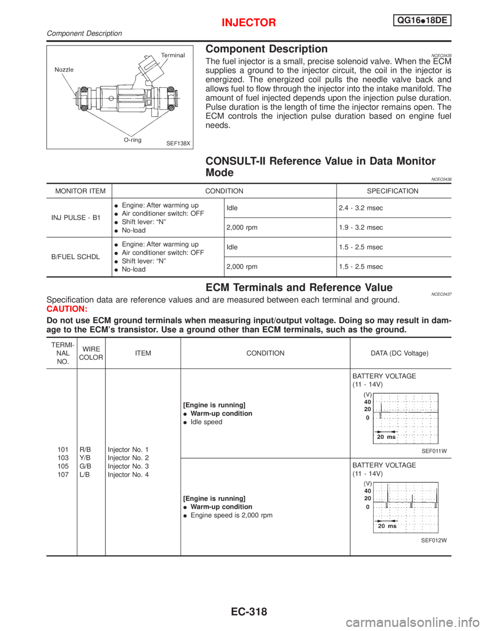
Component DescriptionNCEC0435The fuel injector is a small, precise solenoid valve. When the ECM
supplies a ground to the injector circuit, the coil in the injector is
energized. The energized coil pulls the needle valve back and
allows fuel to flow through the injector into the intake manifold. The
amount of fuel injected depends upon the injection pulse duration.
Pulse duration is the length of time the injector remains open. The
ECM controls the injection pulse duration based on engine fuel
needs.
CONSULT-II Reference Value in Data Monitor
Mode
NCEC0436
MONITOR ITEM CONDITION SPECIFICATION
INJ PULSE - B1IEngine: After warming up
IAir conditioner switch: OFF
IShift lever: ªNº
INo-loadIdle 2.4 - 3.2 msec
2,000 rpm 1.9 - 3.2 msec
B/FUEL SCHDLIEngine: After warming up
IAir conditioner switch: OFF
IShift lever: ªNº
INo-loadIdle 1.5 - 2.5 msec
2,000 rpm 1.5 - 2.5 msec
ECM Terminals and Reference ValueNCEC0437Specification data are reference values and are measured between each terminal and ground.
CAUTION:
Do not use ECM ground terminals when measuring input/output voltage. Doing so may result in dam-
age to the ECM's transistor. Use a ground other than ECM terminals, such as the ground.
TERMI-
NAL
NO.WIRE
COLORITEM CONDITION DATA (DC Voltage)
101
103
105
107R/B
Y/B
G/B
L/BInjector No. 1
Injector No. 2
Injector No. 3
Injector No. 4[Engine is running]
IWarm-up condition
IIdle speedBATTERY VOLTAGE
(11 - 14V)
SEF011W
[Engine is running]
IWarm-up condition
IEngine speed is 2,000 rpmBATTERY VOLTAGE
(11 - 14V)
SEF012W
SEF138X
INJECTORQG16I18DE
Component Description
EC-318
Page 765 of 2267
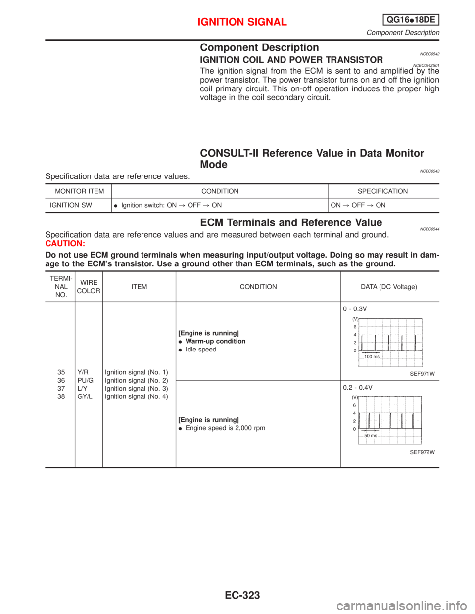
Component DescriptionNCEC0542IGNITION COIL AND POWER TRANSISTORNCEC0542S01The ignition signal from the ECM is sent to and amplified by the
power transistor. The power transistor turns on and off the ignition
coil primary circuit. This on-off operation induces the proper high
voltage in the coil secondary circuit.
CONSULT-II Reference Value in Data Monitor
Mode
NCEC0543Specification data are reference values.
MONITOR ITEM CONDITION SPECIFICATION
IGNITION SWIIgnition switch: ON,OFF,ON ON,OFF,ON
ECM Terminals and Reference ValueNCEC0544Specification data are reference values and are measured between each terminal and ground.
CAUTION:
Do not use ECM ground terminals when measuring input/output voltage. Doing so may result in dam-
age to the ECM's transistor. Use a ground other than ECM terminals, such as the ground.
TERMI-
NAL
NO.WIRE
COLORITEM CONDITION DATA (DC Voltage)
35
36
37
38Y/R
PU/G
L/Y
GY/LIgnition signal (No. 1)
Ignition signal (No. 2)
Ignition signal (No. 3)
Ignition signal (No. 4)[Engine is running]
IWarm-up condition
IIdle speed0 - 0.3V
SEF971W
[Engine is running]
IEngine speed is 2,000 rpm0.2 - 0.4V
SEF972W
IGNITION SIGNALQG16I18DE
Component Description
EC-323
Page 772 of 2267
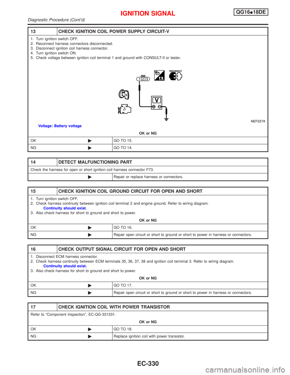
13 CHECK IGNITION COIL POWER SUPPLY CIRCUIT-V
1. Turn ignition switch OFF.
2. Reconnect harness connectors disconnected.
3. Disconnect ignition coil harness connector.
4. Turn ignition switch ON.
5. Check voltage between ignition coil terminal 1 and ground with CONSULT-II or tester.
NEF237AVoltage: Battery voltage
OK or NG
OK©GO TO 15.
NG©GO TO 14.
14 DETECT MALFUNCTIONING PART
Check the harness for open or short ignition coil harness connector F73.
©Repair or replace harness or connectors.
15 CHECK IGNITION COIL GROUND CIRCUIT FOR OPEN AND SHORT
1. Turn ignition switch OFF.
2. Check harness continuity between ignition coil terminal 2 and engine ground. Refer to wiring diagram.
Continuity should exist.
3. Also check harness for short to ground and short to power.
OK or NG
OK©GO TO 16.
NG©Repair open circuit or short to ground or short to power in harness or connectors.
16 CHECK OUTPUT SIGNAL CIRCUIT FOR OPEN AND SHORT
1. Disconnect ECM harness connector.
2. Check harness continuity between ECM terminals 35, 36, 37, 38 and ignition coil terminal 3. Refer to wiring diagram.
Continuity should exist.
3. Also check harness for short to ground and short to power.
OK or NG
OK©GO TO 17.
NG©Repair open circuit or short to ground or short to power in harness or connectors.
17 CHECK IGNITION COIL WITH POWER TRANSISTOR
Refer to ªComponent Inspectionº, EC-QG-331331.
OK or NG
OK©GO TO 18.
NG©Replace ignition coil with power transistor.
IGNITION SIGNALQG16I18DE
Diagnostic Procedure (Cont'd)
EC-330
Page 784 of 2267
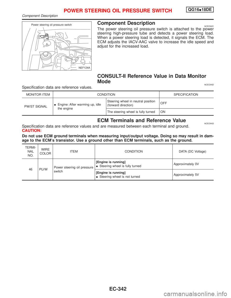
Component DescriptionNCEC0451The power steering oil pressure switch is attached to the power
steering high-pressure tube and detects a power steering load.
When a power steering load is detected, it signals the ECM. The
ECM adjusts the IACV-AAC valve to increase the idle speed and
adjust for the increased load.
CONSULT-II Reference Value in Data Monitor
Mode
NCEC0452Specification data are reference values.
MONITOR ITEM CONDITION SPECIFICATION
PW/ST SIGNALIEngine: After warming up, idle
the engineSteering wheel in neutral position
(forward direction)OFF
The steering wheel is fully turned ON
ECM Terminals and Reference ValueNCEC0453Specification data are reference values and are measured between each terminal and ground.
CAUTION:
Do not use ECM ground terminals when measuring input/output voltage. Doing so may result in dam-
age to the ECM's transistor. Use a ground other than ECM terminals, such as the ground.
TERMI-
NAL
NO.WIRE
COLORITEM CONDITION DATA (DC Voltage)
46 PU/WPower steering oil pressure
switch[Engine is running]
ISteering wheel is fully turnedApproximately 0V
[Engine is running]
ISteering wheel is not turnedApproximately 5V
NEF124A Power steering oil pressure switch
POWER STEERING OIL PRESSURE SWITCHQG16I18DE
Component Description
EC-342
Page 786 of 2267
Diagnostic Procedure=NCEC0454
1 INSPECTION START
Do you have CONSULT-II?
YesorNo
Ye s©GO TO 2.
No©GO TO 3.
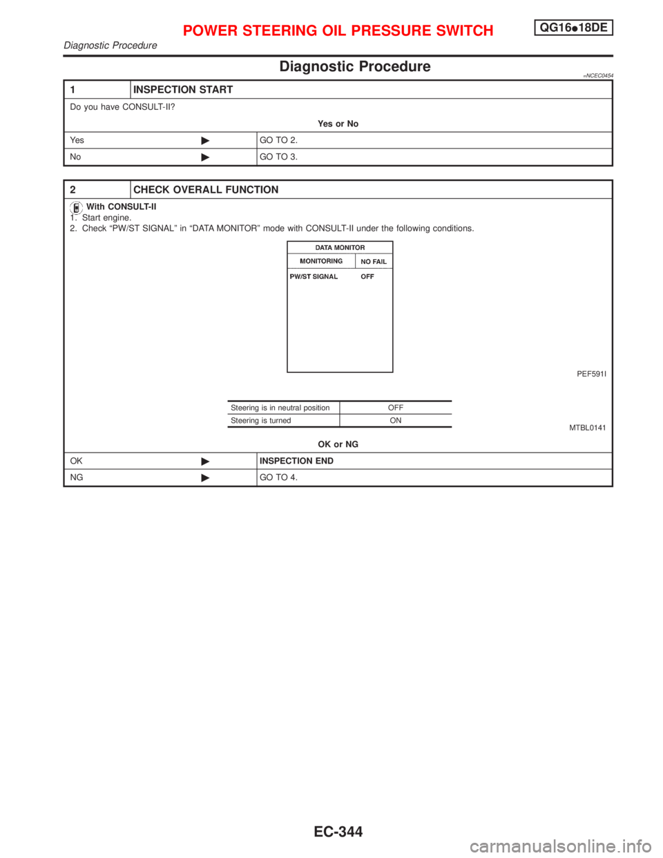
2 CHECK OVERALL FUNCTION
With CONSULT-II
1. Start engine.
2. Check ªPW/ST SIGNALº in ªDATA MONITORº mode with CONSULT-II under the following conditions.
PEF591I
MTBL0141
OK or NG
OK©INSPECTION END
NG©GO TO 4.
Steering is in neutral position OFF
Steering is turned ON
POWER STEERING OIL PRESSURE SWITCHQG16I18DE
Diagnostic Procedure
EC-344
Page 787 of 2267
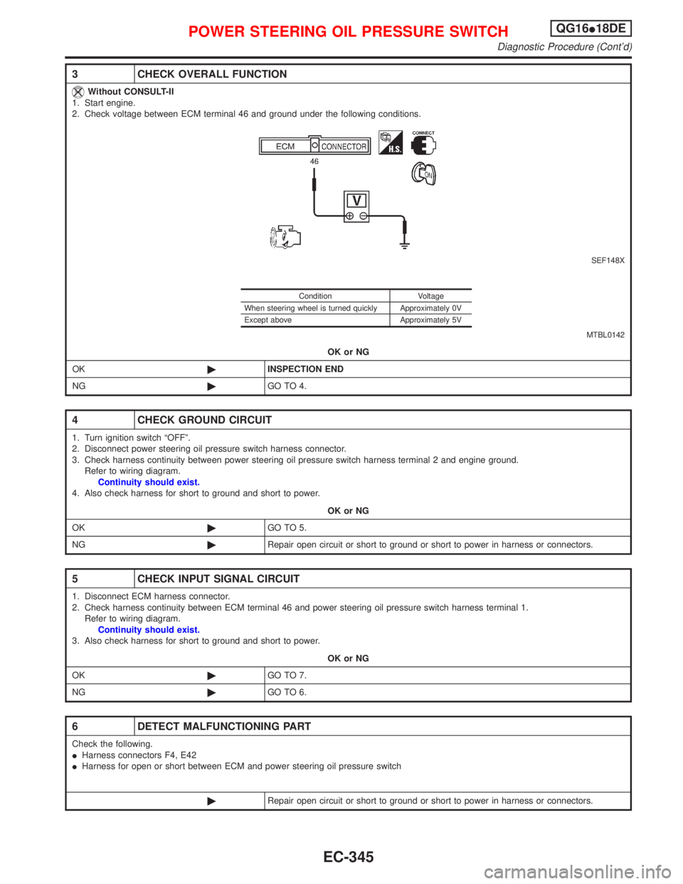
3 CHECK OVERALL FUNCTION
Without CONSULT-II
1. Start engine.
2. Check voltage between ECM terminal 46 and ground under the following conditions.
SEF148X
MTBL0142
OK or NG
OK©INSPECTION END
NG©GO TO 4.
4 CHECK GROUND CIRCUIT
1. Turn ignition switch ªOFFº.
2. Disconnect power steering oil pressure switch harness connector.
3. Check harness continuity between power steering oil pressure switch harness terminal 2 and engine ground.
Refer to wiring diagram.
Continuity should exist.
4. Also check harness for short to ground and short to power.
OK or NG
OK©GO TO 5.
NG©Repair open circuit or short to ground or short to power in harness or connectors.
5 CHECK INPUT SIGNAL CIRCUIT
1. Disconnect ECM harness connector.
2. Check harness continuity between ECM terminal 46 and power steering oil pressure switch harness terminal 1.
Refer to wiring diagram.
Continuity should exist.
3. Also check harness for short to ground and short to power.
OK or NG
OK©GO TO 7.
NG©GO TO 6.
6 DETECT MALFUNCTIONING PART
Check the following.
IHarness connectors F4, E42
IHarness for open or short between ECM and power steering oil pressure switch
©Repair open circuit or short to ground or short to power in harness or connectors.
Condition Voltage
When steering wheel is turned quickly Approximately 0V
Except above Approximately 5V
POWER STEERING OIL PRESSURE SWITCHQG16I18DE
Diagnostic Procedure (Cont'd)
EC-345
Page 788 of 2267
7 CHECK POWER STEERING OIL PRESSURE SWITCH
Refer to ªComponent Inspectionº, EC-QG-346.
OK or NG
OK©GO TO 8.
NG©Replace power steering oil pressure switch.
8 CHECK INTERMITTENT INCIDENT
Perform ªTROUBLE DIAGNOSIS FOR INTERMITTENT INCIDENTº, EC-QG-102.
©INSPECTION END
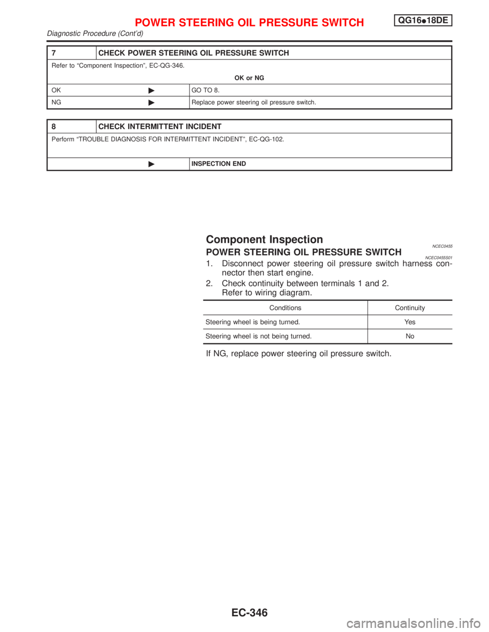
Component InspectionNCEC0455POWER STEERING OIL PRESSURE SWITCHNCEC0455S011. Disconnect power steering oil pressure switch harness con-
nector then start engine.
2. Check continuity between terminals 1 and 2.
Refer to wiring diagram.
Conditions Continuity
Steering wheel is being turned. Yes
Steering wheel is not being turned. No
If NG, replace power steering oil pressure switch.
POWER STEERING OIL PRESSURE SWITCHQG16I18DE
Diagnostic Procedure (Cont'd)
EC-346