Removal and Installation
CAUTION:
lBefore removing the rear suspension assembly, discon-
nect the ABS wheel sensor and headlamp leveling sen-
sor from the assembly. Failure to do so may result in
damage to the sensor wires and the sensor becoming
inoperative.
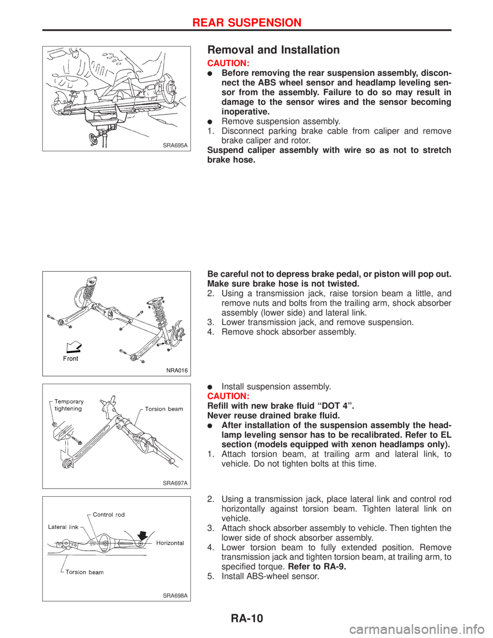
lRemove suspension assembly.
1. Disconnect parking brake cable from caliper and remove
brake caliper and rotor.
Suspend caliper assembly with wire so as not to stretch
brake hose.
Be careful not to depress brake pedal, or piston will pop out.
Make sure brake hose is not twisted.
2. Using a transmission jack, raise torsion beam a little, and
remove nuts and bolts from the trailing arm, shock absorber
assembly (lower side) and lateral link.
3. Lower transmission jack, and remove suspension.
4. Remove shock absorber assembly.
lInstall suspension assembly.
CAUTION:
Refill with new brake fluid ªDOT 4º.
Never reuse drained brake fluid.
lAfter installation of the suspension assembly the head-
lamp leveling sensor has to be recalibrated. Refer to EL
section (models equipped with xenon headlamps only).
1. Attach torsion beam, at trailing arm and lateral link, to
vehicle. Do not tighten bolts at this time.
2. Using a transmission jack, place lateral link and control rod
horizontally against torsion beam. Tighten lateral link on
vehicle.
3. Attach shock absorber assembly to vehicle. Then tighten the
lower side of shock absorber assembly.
4. Lower torsion beam to fully extended position. Remove
transmission jack and tighten torsion beam, at trailing arm, to
specified torque.Refer to RA-9.
5. Install ABS-wheel sensor.
SRA695A
NRA016
SRA697A
SRA698A
REAR SUSPENSION
RA-10
ASSEMBLY
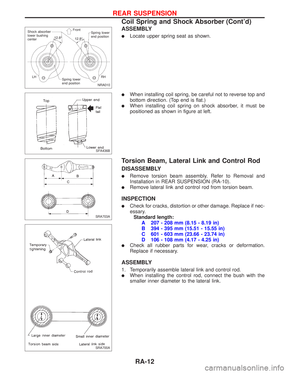
lLocate upper spring seat as shown.
lWhen installing coil spring, be careful not to reverse top and
bottom direction. (Top end is flat.)
lWhen installing coil spring on shock absorber, it must be
positioned as shown in figure at left.
Torsion Beam, Lateral Link and Control Rod
DISASSEMBLY
lRemove torsion beam assembly. Refer to Removal and
Installation in REAR SUSPENSION (RA-10).
lRemove lateral link and control rod from torsion beam.
INSPECTION
lCheck for cracks, distortion or other damage. Replace if nec-
essary.
Standard length:
A 207 - 208 mm (8.15 - 8.19 in)
B 394 - 395 mm (15.51 - 15.55 in)
C 601 - 603 mm (23.66 - 23.74 in)
D 106 - 108 mm (4.17 - 4.25 in)
lCheck all rubber parts for wear, cracks or deformation.
Replace if necessary.
ASSEMBLY
1. Temporarily assemble lateral link and control rod.
lWhen installing the control rod, connect the bush with the
smaller inner diameter to the lateral link.
NRA010 Shock absorber
lower bushing
centerSpring lower
end position
Spring lower
end positionRH LH12.8É
12.8É Front
SFA436B
SRA703A
SRA700A
REAR SUSPENSION
Coil Spring and Shock Absorber (Cont'd)
RA-12

