water pump NISSAN PRIMERA 1999 Electronic User Guide
[x] Cancel search | Manufacturer: NISSAN, Model Year: 1999, Model line: PRIMERA, Model: NISSAN PRIMERA 1999Pages: 2267, PDF Size: 35.74 MB
Page 897 of 2267

SYMPTOM
Reference
page
HARD/NO START/RESTART (EXCP. HA)
ENGINE STALL
HESITATION/SURGING/FLAT SPOT
SPARK KNOCK/DETONATION
LACK OF POWER/POOR ACCELERATION
HIGH IDLE/LOW IDLE
ROUGH IDLE/HUNTING
IDLING VIBRATION
SLOW/NO RETURN TO IDLE
OVERHEATS/WATER TEMPERATURE HIGH
EXCESSIVE FUEL CONSUMPTION
EXCESSIVE OIL CONSUMPTION
BATTERY DEAD (UNDER CHARGE)
Warranty symptom code AA AB AC AD AE AF AG AH AJ AK AL AM HA
Engine Cylinder head
55555 55 5
EM section Cylinder head gasket 4 3
Cylinder block
66666 66 64 Piston
Piston ring
Connecting rod
Bearing
Crankshaft
Valve
mecha-
nismTiming chain
55555 55 5 EMsection Camshaft
Intake valve
3
Exhaust valve
Exhaust Exhaust manifold/Tube/Muffler/
Gasket
55555 55 5 FEsection
Three way catalyst
Lubrica-
tionOil pan/Oil strainer/Oil pump/Oil
filter/Oil gallery
55555 55 5MA, EM and
LC sections
Oil level (Low)/Filthy oil
LC section Cooling Radiator/Hose/Radiator filler cap
55555 55 45 Thermostat 5
Water pump
Water gallery
Cooling fan 5 EC-SR-279
Coolant level (low)/Contaminated
coolantMA section
1 - 6: The numbers refer to the order of inspection.
TROUBLE DIAGNOSIS Ð GENERAL DESCRIPTIONSR20DE
Symptom Matrix Chart (Cont'd)
EC-97
Page 1080 of 2267
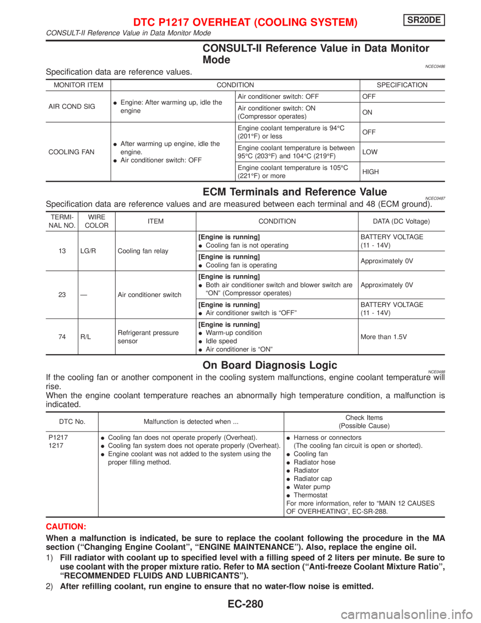
CONSULT-II Reference Value in Data Monitor
Mode
NCEC0486Specification data are reference values.
MONITOR ITEM CONDITION SPECIFICATION
AIR COND SIGIEngine: After warming up, idle the
engineAir conditioner switch: OFF OFF
Air conditioner switch: ON
(Compressor operates)ON
COOLING FANIAfter warming up engine, idle the
engine.
IAir conditioner switch: OFFEngine coolant temperature is 94ÉC
(201ÉF) or lessOFF
Engine coolant temperature is between
95ÉC (203ÉF) and 104ÉC (219ÉF)LOW
Engine coolant temperature is 105ÉC
(221ÉF) or moreHIGH
ECM Terminals and Reference ValueNCEC0487Specification data are reference values and are measured between each terminal and 48 (ECM ground).
TERMI-
NAL NO.WIRE
COLORITEM CONDITION DATA (DC Voltage)
13 LG/R Cooling fan relay[Engine is running]
ICooling fan is not operatingBATTERY VOLTAGE
(11 - 14V)
[Engine is running]
ICooling fan is operatingApproximately 0V
23 Ð Air conditioner switch[Engine is running]
IBoth air conditioner switch and blower switch are
ªONº (Compressor operates)Approximately 0V
[Engine is running]
IAir conditioner switch is ªOFFºBATTERY VOLTAGE
(11 - 14V)
74 R/LRefrigerant pressure
sensor[Engine is running]
IWarm-up condition
IIdle speed
IAir conditioner is ªONºMore than 1.5V
On Board Diagnosis LogicNCE0488If the cooling fan or another component in the cooling system malfunctions, engine coolant temperature will
rise.
When the engine coolant temperature reaches an abnormally high temperature condition, a malfunction is
indicated.
DTC No. Malfunction is detected when ...Check Items
(Possible Cause)
P1217
1217ICooling fan does not operate properly (Overheat).
ICooling fan system does not operate properly (Overheat).
IEngine coolant was not added to the system using the
proper filling method.IHarness or connectors
(The cooling fan circuit is open or shorted).
ICooling fan
IRadiator hose
IRadiator
IRadiator cap
IWater pump
IThermostat
For more information, refer to ªMAIN 12 CAUSES
OF OVERHEATINGº, EC-SR-288.
CAUTION:
When a malfunction is indicated, be sure to replace the coolant following the procedure in the MA
section (ªChanging Engine Coolantº, ªENGINE MAINTENANCEº). Also, replace the engine oil.
1)Fill radiator with coolant up to specified level with a filling speed of 2 liters per minute. Be sure to
use coolant with the proper mixture ratio. Refer to MA section (ªAnti-freeze Coolant Mixture Ratioº,
ªRECOMMENDED FLUIDS AND LUBRICANTSº).
2)After refilling coolant, run engine to ensure that no water-flow noise is emitted.
DTC P1217 OVERHEAT (COOLING SYSTEM)SR20DE
CONSULT-II Reference Value in Data Monitor Mode
EC-280
Page 1086 of 2267

8 CHECK COOLING FAN RELAY
Refer to ªComponent Inspectionº, EC-SR-289.
OK or NG
OK©GO TO 9.
NG©Replace cooling fan relay.
9 CHECK COOLING FAN MOTORS-1 AND -2
Refer to ªComponent Inspectionº, EC-SR-289.
OK or NG
OK©GO TO 10.
NG©Replace cooling fan motors.
10 CHECK INTERMITTENT INCIDENT
Perform ªTROUBLE DIAGNOSIS FOR INTERMITTENT INCIDENTº, EC-SR-114.
©INSPECTION END
11 CHECK COOLING SYSTEM FOR LEAK
Apply pressure to the cooling system with a tester, and check if the pressure drops.
Testing pressure: 157 kPa (1.57 bar, 1.6 kg/cm2, 23 psi)
CAUTION:
Higher than the specified pressure may cause radiator damage.
SLC754APressure should not drop.
OK or NG
OK©GO TO 12.
NG©Check the following for leak
IHose
IRadiator
IWater pump
Refer to LC section (ªWater Pumpº).
DTC P1217 OVERHEAT (COOLING SYSTEM)SR20DE
Diagnostic Procedure (Cont'd)
EC-286
Page 1551 of 2267
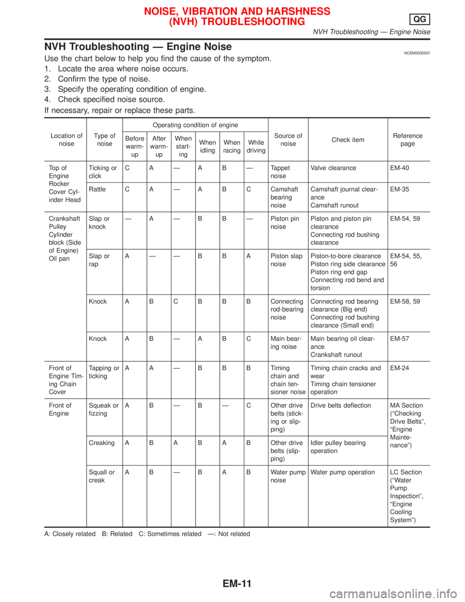
NVH Troubleshooting Ð Engine NoiseNCEM0005S01Use the chart below to help you find the cause of the symptom.
1. Locate the area where noise occurs.
2. Confirm the type of noise.
3. Specify the operating condition of engine.
4. Check specified noise source.
If necessary, repair or replace these parts.
Location of
noiseType of
noiseOperating condition of engine
Source of
noiseCheck itemReference
page Before
warm-
upAfter
warm-
upWhen
start-
ingWhen
idlingWhen
racingWhile
driving
To p o f
Engine
Rocker
Cover Cyl-
inder HeadTicking or
clickC A Ð A B Ð Tappet
noiseValve clearance EM-40
Rattle C A Ð A B C Camshaft
bearing
noiseCamshaft journal clear-
ance
Camshaft runoutEM-35
Crankshaft
Pulley
Cylinder
block (Side
of Engine)
Oil panSlap or
knockÐ A Ð B B Ð Piston pin
noisePiston and piston pin
clearance
Connecting rod bushing
clearanceEM-54, 59
Slap or
rapA Ð Ð B B A Piston slap
noisePiston-to-bore clearance
Piston ring side clearance
Piston ring end gap
Connecting rod bend and
torsionEM-54, 55,
56
Knock A B CB B B Connecting
rod-bearing
noiseConnecting rod bearing
clearance (Big end)
Connecting rod bushing
clearance (Small end)EM-58, 59
Knock A B Ð A B C Main bear-
ing noiseMain bearing oil clear-
ance
Crankshaft runoutEM-57
Front of
Engine Tim-
ing Chain
CoverTapping or
tickingAAÐBBBTiming
chain and
chain ten-
sioner noiseTiming chain cracks and
wear
Timing chain tensioner
operationEM-24
Front of
EngineSqueak or
fizzingA B Ð B Ð C Other drive
belts (stick-
ing or slip-
ping)Drive belts deflection MA Section
(ªChecking
Drive Beltsº,
ªEngine
Mainte-
nanceº) CreakingABABABOther drive
belts (slip-
ping)Idler pulley bearing
operation
Squall or
creakABÐBABWater pump
noiseWater pump operation LC Section
(ªWater
Pump
Inspectionº,
ªEngine
Cooling
Systemº)
A: Closely related B: Related C: Sometimes related Ð: Not related
NOISE, VIBRATION AND HARSHNESS
(NVH) TROUBLESHOOTINGQG
NVH Troubleshooting Ð Engine Noise
EM-11
Page 1552 of 2267

SEM937F Camshaft bearing noise
Tappet noise
Timing chain
and chain
tensioner noise
VALVE MECHANISM
Valve
Piston pin noiseTIMING CHAIN
Water pump noise
ROTATION
MECHANISM
DRIVE BELT
Connecting rod
bearing noise
Piston slap noise
Main bearing noise
NOISE, VIBRATION AND HARSHNESS
(NVH) TROUBLESHOOTINGQG
NVH Troubleshooting Ð Engine Noise (Cont'd)
EM-12
Page 1553 of 2267

Removal and InstallationNCEM0006
1. Oil pressure switch
2. EGR valve*
3. EGR guide tube*
4. Air relief plug5. Intake manifold
6. Intake manifold upper support
7. Intake manifold rear supports
8. Oil filter9. Thermostat
10. Water pump
11. Water pump pulley
*: If so equipped
YEM026
OUTER COMPONENT PARTSQG
Removal and Installation
EM-13
Page 1563 of 2267
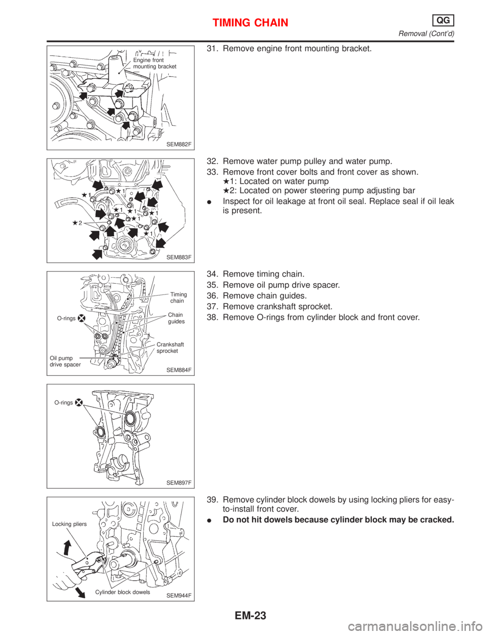
31. Remove engine front mounting bracket.
32. Remove water pump pulley and water pump.
33. Remove front cover bolts and front cover as shown.
H1: Located on water pump
H2: Located on power steering pump adjusting bar
IInspect for oil leakage at front oil seal. Replace seal if oil leak
is present.
34. Remove timing chain.
35. Remove oil pump drive spacer.
36. Remove chain guides.
37. Remove crankshaft sprocket.
38. Remove O-rings from cylinder block and front cover.
39. Remove cylinder block dowels by using locking pliers for easy-
to-install front cover.
IDo not hit dowels because cylinder block may be cracked.
SEM882F Engine front
mounting bracket
SEM883F
SEM884FTiming
chain
Chain
guides
Crankshaft
sprocket
Oil pump
drive spacerO-rings
SEM897F O-rings
SEM944F Locking pliers
Cylinder block dowels
TIMING CHAINQG
Removal (Cont'd)
EM-23
Page 1565 of 2267
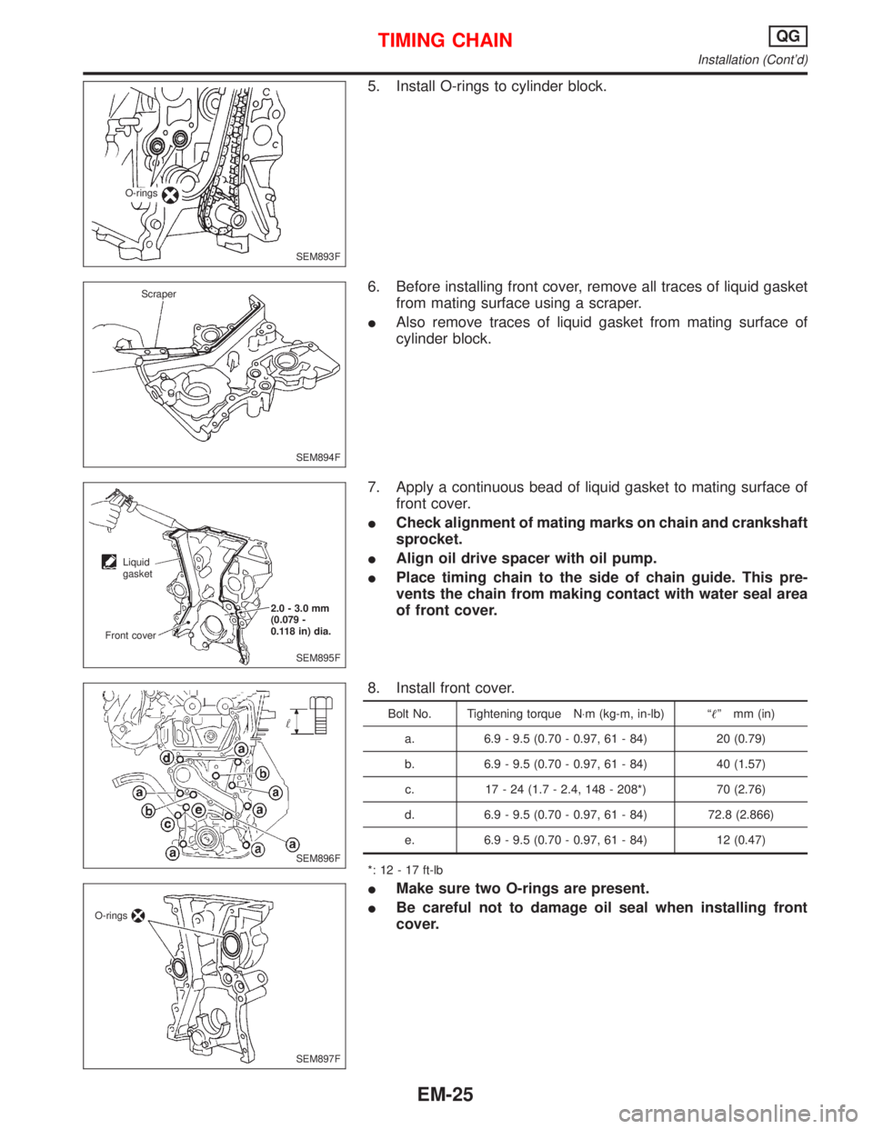
5. Install O-rings to cylinder block.
6. Before installing front cover, remove all traces of liquid gasket
from mating surface using a scraper.
IAlso remove traces of liquid gasket from mating surface of
cylinder block.
7. Apply a continuous bead of liquid gasket to mating surface of
front cover.
ICheck alignment of mating marks on chain and crankshaft
sprocket.
IAlign oil drive spacer with oil pump.
IPlace timing chain to the side of chain guide. This pre-
vents the chain from making contact with water seal area
of front cover.
8. Install front cover.
Bolt No. Tightening torque N×m (kg-m, in-lb) ªº mm (in)
a. 6.9 - 9.5 (0.70 - 0.97, 61 - 84) 20 (0.79)
b. 6.9 - 9.5 (0.70 - 0.97, 61 - 84) 40 (1.57)
c. 17 - 24 (1.7 - 2.4, 148 - 208*) 70 (2.76)
d. 6.9 - 9.5 (0.70 - 0.97, 61 - 84) 72.8 (2.866)
e. 6.9 - 9.5 (0.70 - 0.97, 61 - 84) 12 (0.47)
*: 12 - 17 ft-lb
IMake sure two O-rings are present.
IBe careful not to damage oil seal when installing front
cover.
SEM893F O-rings
SEM894F Scraper
SEM895F 2.0 - 3.0 mm
(0.079 -
0.118 in) dia.
Liquid
gasket
Front cover
SEM896F
SEM897F O-rings
TIMING CHAINQG
Installation (Cont'd)
EM-25
Page 1566 of 2267
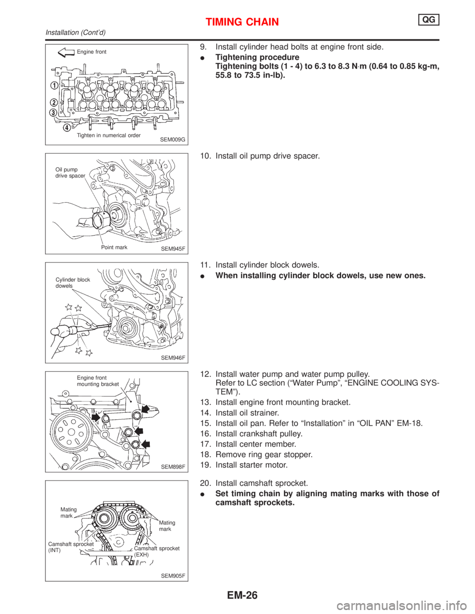
9. Install cylinder head bolts at engine front side.
ITightening procedure
Tightening bolts (1 - 4) to 6.3 to 8.3 N×m (0.64 to 0.85 kg-m,
55.8 to 73.5 in-lb).
10. Install oil pump drive spacer.
11. Install cylinder block dowels.
IWhen installing cylinder block dowels, use new ones.
12. Install water pump and water pump pulley.
Refer to LC section (ªWater Pumpº, ªENGINE COOLING SYS-
TEMº).
13. Install engine front mounting bracket.
14. Install oil strainer.
15. Install oil pan. Refer to ªInstallationº in ªOIL PANº EM-18.
16. Install crankshaft pulley.
17. Install center member.
18. Remove ring gear stopper.
19. Install starter motor.
20. Install camshaft sprocket.
ISet timing chain by aligning mating marks with those of
camshaft sprockets.
SEM009G Engine front
Tighten in numerical order
SEM945F Oil pump
drive spacer
Point mark
SEM946F Cylinder block
dowels
SEM898F Engine front
mounting bracket
SEM905F Mating
mark
Camshaft sprocket
(INT)Mating
mark
Camshaft sprocket
(EXH)
TIMING CHAINQG
Installation (Cont'd)
EM-26
Page 1604 of 2267
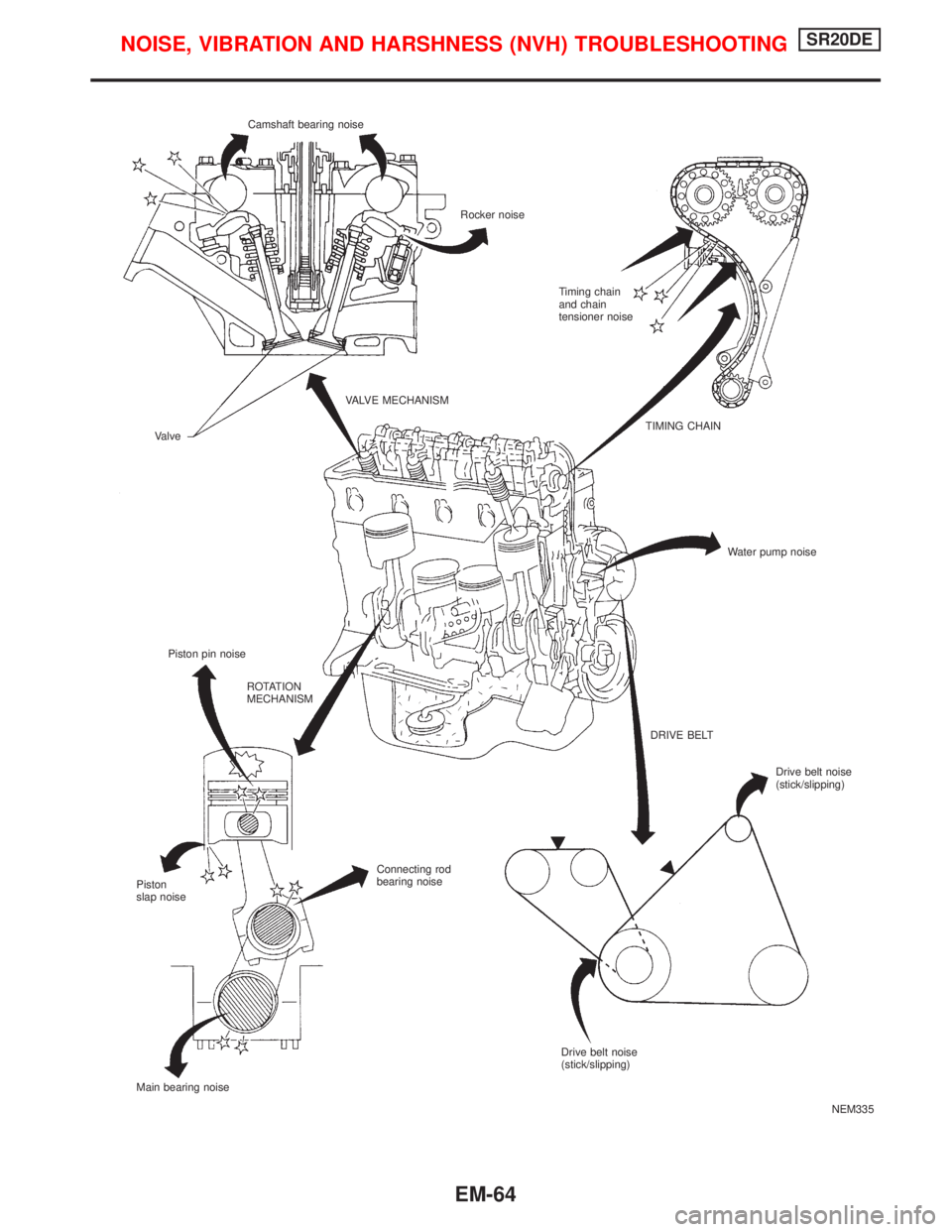
NEM335 Camshaft bearing noise
Rocker noise
Timing chain
and chain
tensioner noise
VALVE MECHANISM
Valve
Piston pin noiseTIMING CHAIN
Water pump noise
ROTATION
MECHANISM
DRIVE BELT
Connecting rod
bearing noise
Piston
slap noise
Main bearing noiseDrive belt noise
(stick/slipping)
Drive belt noise
(stick/slipping)
NOISE, VIBRATION AND HARSHNESS (NVH) TROUBLESHOOTINGSR20DE
EM-64