water pump NISSAN PRIMERA 1999 Electronic Owner's Manual
[x] Cancel search | Manufacturer: NISSAN, Model Year: 1999, Model line: PRIMERA, Model: NISSAN PRIMERA 1999Pages: 2267, PDF Size: 35.74 MB
Page 1605 of 2267
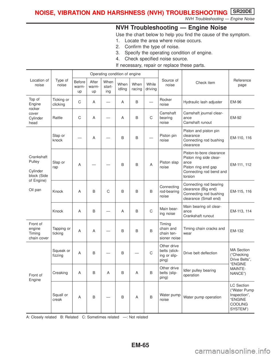
NVH Troubleshooting Ð Engine Noise
Use the chart below to help you find the cause of the symptom.
1. Locate the area where noise occurs.
2. Confirm the type of noise.
3. Specify the operating condition of engine.
4. Check specified noise source.
If necessary, repair or replace these parts.
Location of
noiseType of
noiseOperating condition of engine
Source of
noiseCheck itemReference
page Before
warm-
upAfter
warm-
upWhen
start-
ingWhen
idlingWhen
racingWhile
driving
To p o f
Engine
rocker
cover
Cylinder
headTicking or
clickingC AÐA BÐRocker
noiseHydraulic lash adjuster EM-96
Rattle C A Ð A B CCamshaft
bearing
noiseCamshaft journal clear-
ance
Camshaft runoutEM-92
Crankshaft
Pulley
Cylinder
block (Side
of Engine)
Oil panSlap or
knockÐAÐB BÐPiston pin
noisePiston and piston pin
clearance
Connecting rod bushing
clearanceEM-110, 116
Slap or
rapAÐÐB B APiston slap
noisePiston-to-bore clearance
Piston ring side clear-
ance
Piston ring end gap
Connecting rod bend and
torsionEM-111, 112
Knock A B C B B BConnecting
rod-bearing
noiseConnecting rod bearing
clearance (Big end)
Connecting rod bushing
clearance (Small end)EM-115, 116
Knock A B Ð A B CMain bear-
ing noiseMain bearing oil clear-
ance
Crankshaft runoutEM-113, 114
Front of
engine
Timing
chain coverTapping or
tickingAAÐBBBTiming
chain and
chain ten-
sioner noiseTiming chain cracks and
wearEM-132
Front of
EngineSqueak or
fizzingA BÐBÐCOther drive
belts (stick-
ing or slip-
ping)Drive belt deflectionMA Section
(ªChecking
Drive Beltsº,
ªENGINE
MAINTE-
NANCEº) CreakingABABABOther drive
belts (slip-
ping)Idler pulley bearing
operation
Squall or
creakABÐBABWater pump
noiseWater pump operationLC Section
(ªWater Pump
Inspectionº,
ªENGINE
COOLING
SYSTEMº)
A: Closely related B: Related C: Sometimes related Ð: Not related
NOISE, VIBRATION AND HARSHNESS (NVH) TROUBLESHOOTINGSR20DE
NVH Troubleshooting Ð Engine Noise
EM-65
Page 1606 of 2267
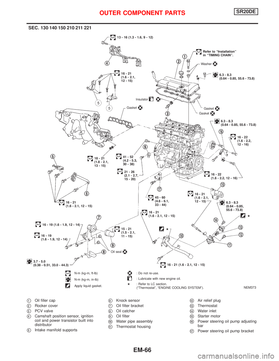
p1Oil filler cap
p2Rocker cover
p3PCV valve
p4Camshaft position sensor, ignition
coil and power transistor built into
distributor
p5Intake manifold supports
p6Knock sensor
p7Oil filter bracket
p8Oil catcher
p9Oil filter
p10Water pipe assembly
p11Thermostat housing
p12Air relief plug
p13Thermostat
p14Water inlet
p15Starter motor
p16Power steering oil pump adjusting
bar
p17Power steering oil pump bracket
NEM373
SEC. 130×140×150×210×211×221
.41-52
(4.2 - 5.3,
30 - 38)Insulator
21-26
(2.1 - 2.7,
15 - 20)
18-21
(1.8 - 2.1,
13 - 15)
16-21
(1.6 - 2.1, 12 - 15)
45-60
(4.6 - 6.1,
33 - 44)
16-21
(1.6 - 2.1, 12 - 15)
16 - 19 (1.6 - 1.9, 12 - 14)Gasket
13 - 16 (1.3 - 1.6, 9 - 12)
Gasket
Gasket
Washer
6.3 - 8.3
(0.64 - 0.85, 55.6 - 73.8)
Refer to ªInstallationº
in ªTIMING CHAINº.
6.3 - 8.3
(0.64 - 0.85, 55.6 - 73.8)
16-22
(1.6 - 2.2,
12 - 16)
.16-22
(1.6 - 2.2, 12 - 16)
16-21
(1.6 - 2.1,
12 - 15)
6.3 - 8.3
(0.64 - 0.85,
55.6 - 73.8)
16 - 21 (1.6 - 2.1, 12 - 15)
16-19
(1.6 - 1.9, 12 - 14)
15-21
(1.5 - 2.1,
11 - 15)
3.7 - 5.0
(0.38 - 0.51, 33.0 - 44.3)
N´m (kg-m, ft-lb)
N´m (kg-m, in-lb)
Apply liquid gasket.Oil seal
: Do not re-use.
: Lubricate with new engine oil.
: Refer to LC section.
(ªThermostatº, ªENGINE COOLING SYSTEMº).
H
H
H
16-21
(1.6 - 2.1,
12 - 15)
OUTER COMPONENT PARTSSR20DE
EM-66
Page 1616 of 2267
CAUTION:
IAfter removing timing chain, do not turn crankshaft and
camshaft separately, or valves will strike piston heads.
IWhen installing chain tensioner, oil seals, or other sliding
parts, lubricate contacting surfaces with new engine oil.
IApply new engine oil to bolt threads and seat surfaces
when installing camshaft sprocket and crankshaft pulley.
RemovalNLEM01261. Remove engine under cover.
2. Remove front RH wheel and engine side cover.
3. Drain coolant by removing cylinder block drain plug and lower
radiator hose. Refer to MA-29, ªChanging Engine Coolantº.
4. Remove drive belts and water pump pulley.
5. Disconnect the following parts:
IVacuum hoses
IWires
IHarness
IConnectors
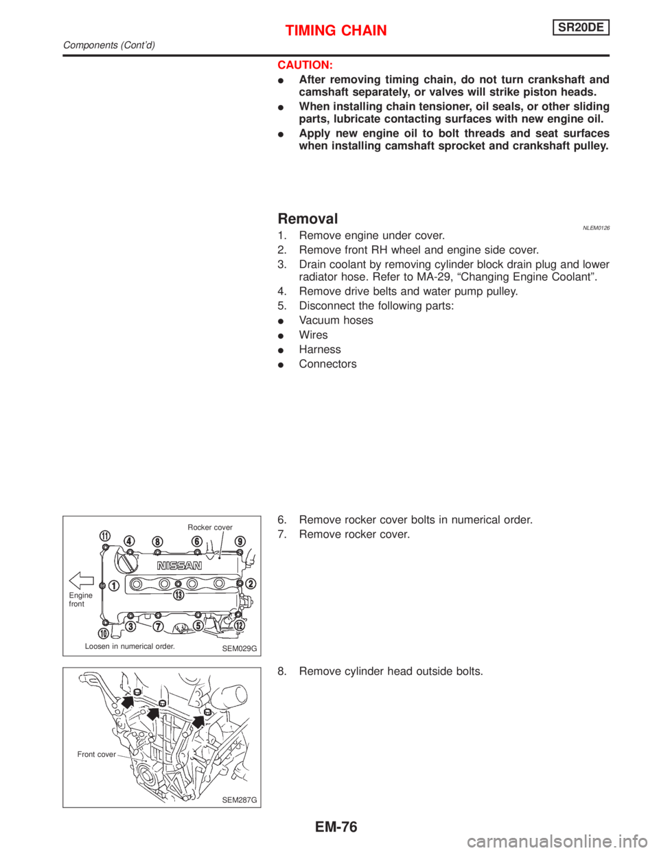
6. Remove rocker cover bolts in numerical order.
7. Remove rocker cover.
8. Remove cylinder head outside bolts.
SEM029G Engine
front
Loosen in numerical order.Rocker cover
SEM287G Front cover
TIMING CHAINSR20DE
Components (Cont'd)
EM-76
Page 1618 of 2267
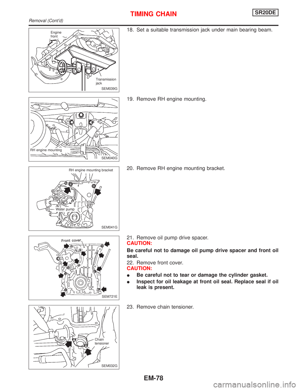
18. Set a suitable transmission jack under main bearing beam.
19. Remove RH engine mounting.
20. Remove RH engine mounting bracket.
21. Remove oil pump drive spacer.
CAUTION:
Be careful not to damage oil pump drive spacer and front oil
seal.
22. Remove front cover.
CAUTION:
IBe careful not to tear or damage the cylinder gasket.
IInspect for oil leakage at front oil seal. Replace seal if oil
leak is present.
23. Remove chain tensioner.
SEM039G Engine
front
Transmission
jack
SEM040G RH engine mounting
SEM041G RH engine mounting bracket
Water pump
SEM721E
.SEM032G Chain
tensioner
TIMING CHAINSR20DE
Removal (Cont'd)
EM-78
Page 1623 of 2267
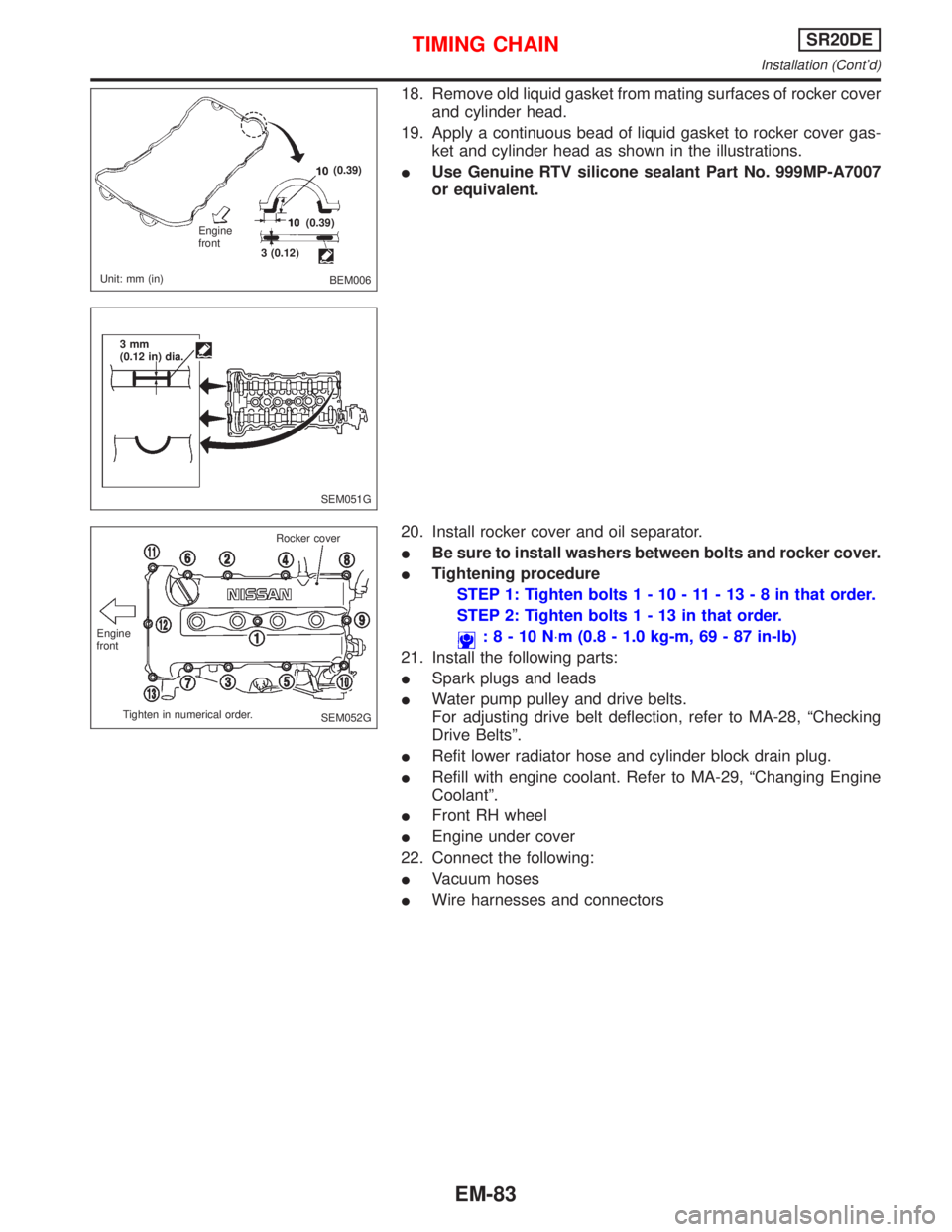
18. Remove old liquid gasket from mating surfaces of rocker cover
and cylinder head.
19. Apply a continuous bead of liquid gasket to rocker cover gas-
ket and cylinder head as shown in the illustrations.
IUse Genuine RTV silicone sealant Part No. 999MP-A7007
or equivalent.
20. Install rocker cover and oil separator.
IBe sure to install washers between bolts and rocker cover.
ITightening procedure
STEP 1: Tighten bolts1-10-11-13-8inthat order.
STEP 2: Tighten bolts1-13inthat order.
:8-10N×m (0.8 - 1.0 kg-m, 69 - 87 in-lb)
21. Install the following parts:
ISpark plugs and leads
IWater pump pulley and drive belts.
For adjusting drive belt deflection, refer to MA-28, ªChecking
Drive Beltsº.
IRefit lower radiator hose and cylinder block drain plug.
IRefill with engine coolant. Refer to MA-29, ªChanging Engine
Coolantº.
IFront RH wheel
IEngine under cover
22. Connect the following:
IVacuum hoses
IWire harnesses and connectors
BEM006 Engine
front
Unit: mm (in)3 (0.12)(0.39)
(0.39)
SEM051G 3mm
(0.12 in) dia.
SEM052G Engine
front
Tighten in numerical order.Rocker cover
TIMING CHAINSR20DE
Installation (Cont'd)
EM-83
Page 1649 of 2267
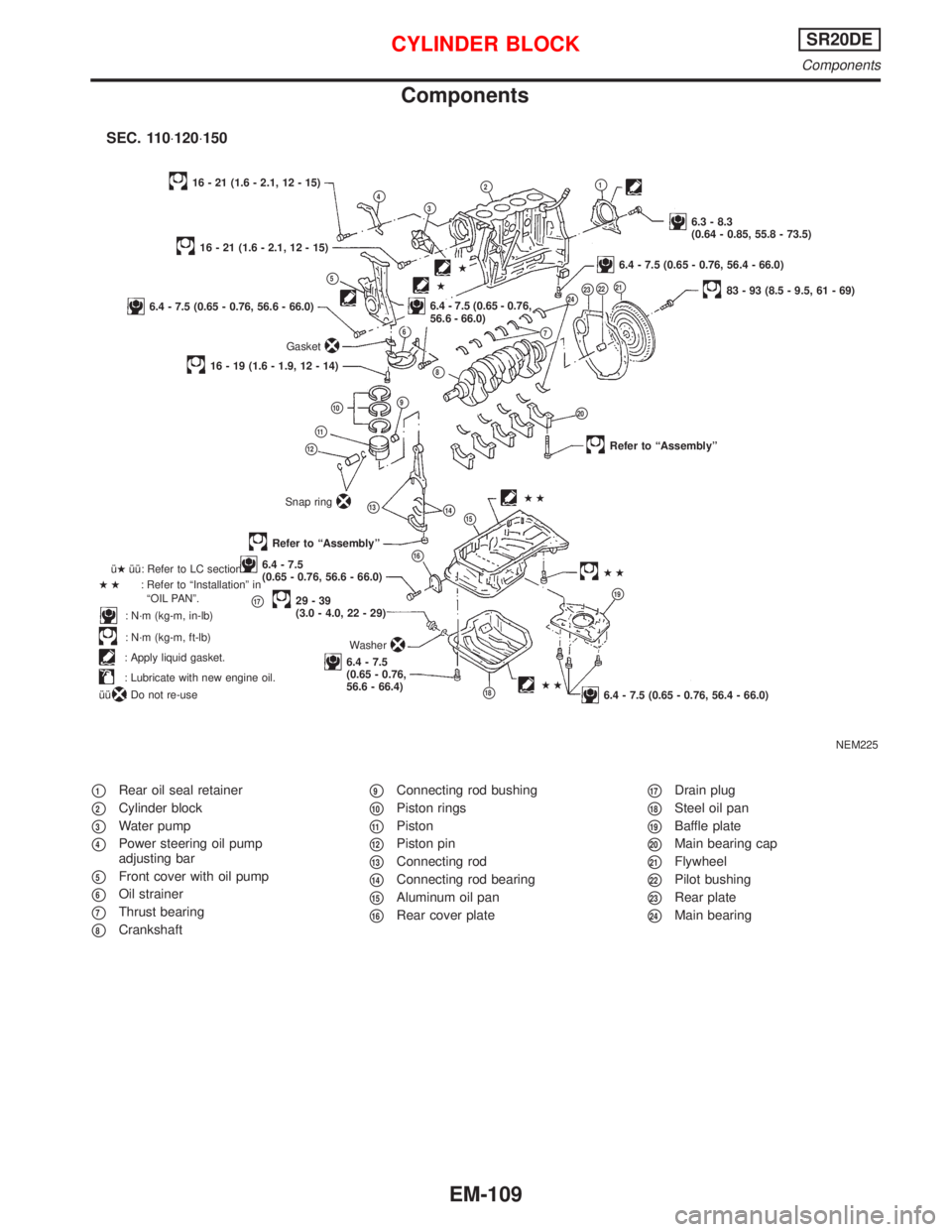
Components
p1Rear oil seal retainer
p2Cylinder block
p3Water pump
p4Power steering oil pump
adjusting bar
p5Front cover with oil pump
p6Oil strainer
p7Thrust bearing
p8Crankshaft
p9Connecting rod bushing
p10Piston rings
p11Piston
p12Piston pin
p13Connecting rod
p14Connecting rod bearing
p15Aluminum oil pan
p16Rear cover plate
p17Drain plug
p18Steel oil pan
p19Baffle plate
p20Main bearing cap
p21Flywheel
p22Pilot bushing
p23Rear plate
p24Main bearing
NEM225
p4p3
p2p1
6.3 - 8.3
(0.64 - 0.85, 55.8 - 73.5)
16 - 21 (1.6 - 2.1, 12 - 15)
p5
16 - 21 (1.6 - 2.1, 12 - 15)
6.4 - 7.5 (0.65 - 0.76, 56.6 - 66.0)
Gasket
p6
.6.4 - 7.5 (0.65 - 0.76,
56.6 - 66.0)
16 - 19 (1.6 - 1.9, 12 - 14)
p2383 - 93 (8.5 - 9.5, 61 - 69)
p10p9
p8
p22
p11
p12
Snap ringp14
Refer to ªAssemblyº
Refer to ªAssemblyº
p166.4 - 7.5
(0.65 - 0.76, 56.6 - 66.0)
p1729-39
(3.0 - 4.0, 22 - 29)
6.4 - 7.5
(0.65 - 0.76,
56.6 - 66.4) îHîî: Refer to LC section.
HH: Refer to ªInstallationº in
ªOIL PANº.
: N´m (kg-m, in-lb)
: N´m (kg-m, ft-lb)
: Apply liquid gasket.
: Lubricate with new engine oil.
îî
: Do not re-useHH
p24
Washer
p21
p20
HH
p19
6.4 - 7.5 (0.65 - 0.76, 56.4 - 66.0)
p13HH
p7
6.4 - 7.5 (0.65 - 0.76, 56.4 - 66.0).H
H
SEC. 110×120×150
p15
p18
CYLINDER BLOCKSR20DE
Components
EM-109
Page 1661 of 2267
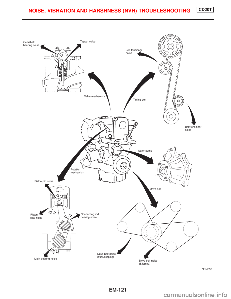
NEM333 Camshaft
bearing noiseTappet noise
Belt tensioner
noise
Valve mechanism
Piston pin noiseTiming belt
Water pump
Rotation
mechanism
Drive belt
Connecting rod
bearing noise Piston
slap noise
Main bearing noiseDrive belt noise
(stick/slipping)
Belt tensioner
noise
Drive belt noise
(Slipping)
NOISE, VIBRATION AND HARSHNESS (NVH) TROUBLESHOOTINGCD20T
EM-121
Page 1662 of 2267
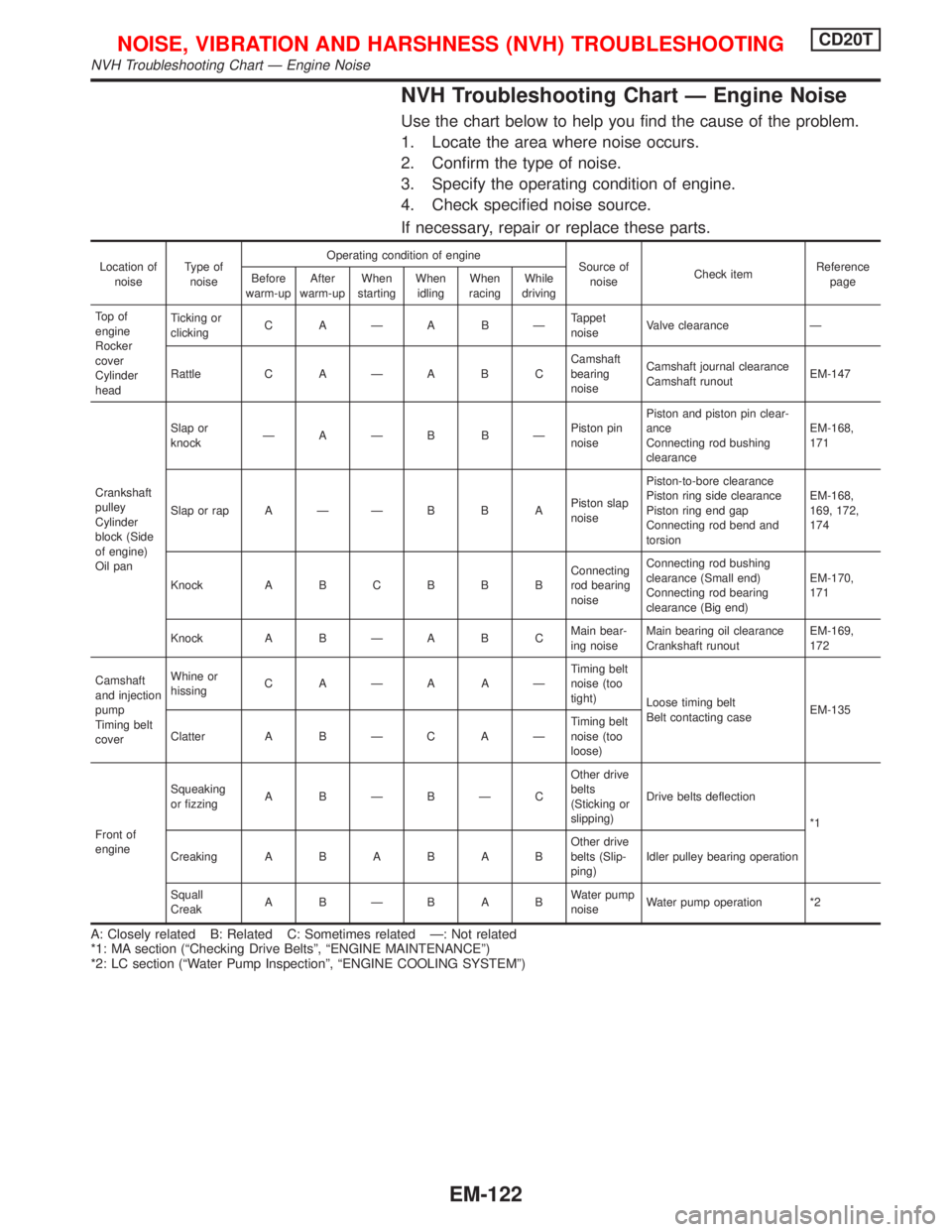
NVH Troubleshooting Chart Ð Engine Noise
Use the chart below to help you find the cause of the problem.
1. Locate the area where noise occurs.
2. Confirm the type of noise.
3. Specify the operating condition of engine.
4. Check specified noise source.
If necessary, repair or replace these parts.
Location of
noiseType of
noiseOperating condition of engine
Source of
noiseCheck itemReference
page Before
warm-upAfter
warm-upWhen
startingWhen
idlingWhen
racingWhile
driving
To p o f
engine
Rocker
cover
Cylinder
headTicking or
clickingCAÐABÐTappet
noiseValve clearance Ð
Rattle C A Ð A B CCamshaft
bearing
noiseCamshaft journal clearance
Camshaft runoutEM-147
Crankshaft
pulley
Cylinder
block (Side
of engine)
Oil panSlap or
knockÐAÐB BÐPiston pin
noisePiston and piston pin clear-
ance
Connecting rod bushing
clearanceEM-168,
171
Slap or rap A Ð Ð B B APiston slap
noisePiston-to-bore clearance
Piston ring side clearance
Piston ring end gap
Connecting rod bend and
torsionEM-168,
169, 172,
174
Knock A B C B B BConnecting
rod bearing
noiseConnecting rod bushing
clearance (Small end)
Connecting rod bearing
clearance (Big end)EM-170,
171
Knock A B Ð A B CMain bear-
ing noiseMain bearing oil clearance
Crankshaft runoutEM-169,
172
Camshaft
and injection
pump
Timing belt
coverWhine or
hissingCAÐAAÐTiming belt
noise (too
tight)
Loose timing belt
Belt contacting caseEM-135
Clatter A B Ð C A ÐTiming belt
noise (too
loose)
Front of
engineSqueaking
or fizzingABÐBÐCOther drive
belts
(Sticking or
slipping)Drive belts deflection
*1
CreakingABABABOther drive
belts (Slip-
ping)Idler pulley bearing operation
Squall
CreakABÐBABWater pump
noiseWater pump operation *2
A: Closely related B: Related C: Sometimes related Ð: Not related
*1: MA section (ªChecking Drive Beltsº, ªENGINE MAINTENANCEº)
*2: LC section (ªWater Pump Inspectionº, ªENGINE COOLING SYSTEMº)
NOISE, VIBRATION AND HARSHNESS (NVH) TROUBLESHOOTINGCD20T
NVH Troubleshooting Chart Ð Engine Noise
EM-122
Page 1663 of 2267
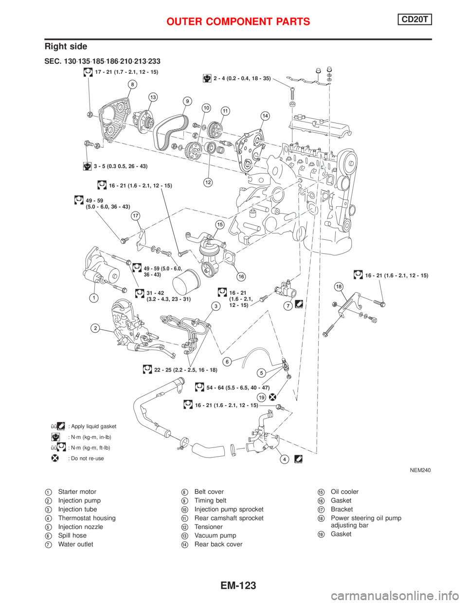
Right side
p1Starter motor
p2Injection pump
p3Injection tube
p4Thermostat housing
p5Injection nozzle
p6Spill hose
p7Water outlet
p8Belt cover
p9Timing belt
p10Injection pump sprocket
p11Rear camshaft sprocket
p12Tensioner
p13Vacuum pump
p14Rear back cover
p15Oil cooler
p16Gasket
p17Bracket
p18Power steering oil pump
adjusting bar
p19Gasket
NEM240
17 - 21 (1.7 - 2.1, 12 - 15)2 - 4 (0.2 - 0.4, 18 - 35)
3 - 5 (0.3 0.5, 26 - 43)
49-59
(5.0 - 6.0, 36 - 43)
49 - 59 (5.0 - 6.0,
36 - 43)
31-42
(3.2 - 4.3, 23 - 31)16-21
(1.6 - 2.1,
12 - 15)
16 - 21 (1.6 - 2.1, 12 - 15)
54 - 64 (5.5 - 6.5, 40 - 47)
22 - 25 (2.2 - 2.5, 16 - 18)
16 - 21 (1.6 - 2.1, 12 - 15)
SEC. 130×135×185×186×210×213×233
îî: Apply liquid gasket
: N´m (kg-m, in-lb)
îî
: N´m (kg-m, ft-lb)
: Do not re-use
16 - 21 (1.6 - 2.1, 12 - 15)
OUTER COMPONENT PARTSCD20T
EM-123
Page 1664 of 2267
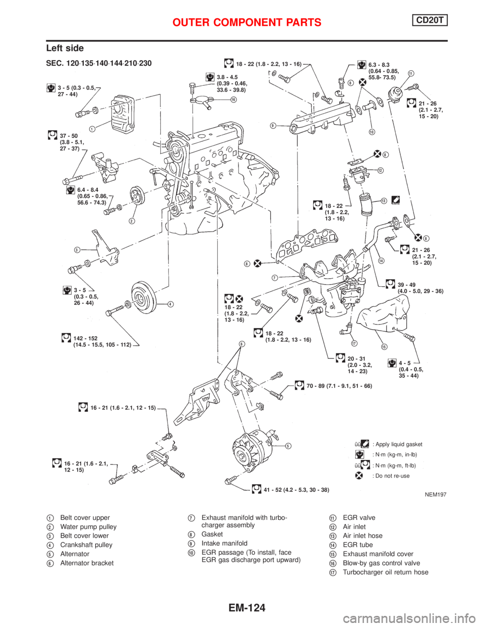
Left side
p1Belt cover upper
p2Water pump pulley
p3Belt cover lower
p4Crankshaft pulley
p5Alternator
p6Alternator bracket
p7Exhaust manifold with turbo-
charger assembly
p8Gasket
p9Intake manifold
p10EGR passage (To install, face
EGR gas discharge port upward)
p11EGR valve
p12Air inlet
p13Air inlet hose
p14EGR tube
p15Exhaust manifold cover
p16Blow-by gas control valve
p17Turbocharger oil return hose
3 - 5 (0.3 - 0.5,
27 - 44)
37-50
(3.8 - 5.1,
27 - 37)p1
6.4 - 8.4
(0.65 - 0.86,
56.6 - 74.3)
p2
p9
p3
3-5
(0.3 - 0.5,
26 - 44)
p4
142 - 152
(14.5 - 15.5, 105 - 112)p6
16 - 21 (1.6 - 2.1, 12 - 15)
16 - 21 (1.6 - 2.1,
12 - 15)îî
: Apply liquid gasket
: N´m (kg-m, in-lb)
îî
: N´m (kg-m, ft-lb)
: Do not re-use
18 - 22 (1.8 - 2.2, 13 - 16)6.3 - 8.3
(0.64 - 0.85,
55.8- 73.5)
p11
p8
p10
.21-26
(2.1 - 2.7,
15 - 20)
p8
p12
p1318-22
(1.8 - 2.2,
13 - 16)
p8
21-26
(2.1 - 2.7,
15 - 20)
p14
39-49
(4.0 - 5.0, 29 - 36)
p8
p7
18-22
(1.8 - 2.2,
13 - 16)
.18-22
(1.8 - 2.2, 13 - 16)
p17p15
4-5
(0.4 - 0.5,
35 - 44)
70 - 89 (7.1 - 9.1, 51 - 66)
p5
41 - 52 (4.2 - 5.3, 30 - 38)
NEM197
SEC. 120×135×140×144×210×230
3.8 - 4.5
(0.39 - 0.46,
33.6 - 39.8)
p16
20-31
(2.0 - 3.2,
14 - 23)
OUTER COMPONENT PARTSCD20T
EM-124