NISSAN PRIMERA 1999 Electronic Repair Manual
PRIMERA 1999
NISSAN
NISSAN
https://www.carmanualsonline.info/img/5/57377/w960_57377-0.png
NISSAN PRIMERA 1999 Electronic Repair Manual
Trending: Oil engine, jacking points, clock setting, check transmission fluid, low oil pressure, alarm, auxiliary battery
Page 2101 of 2267
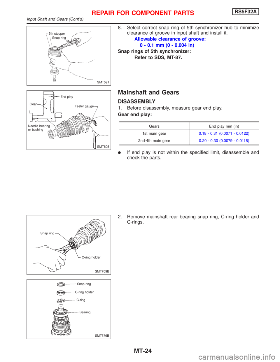
8. Select correct snap ring of 5th synchronizer hub to minimize
clearance of groove in input shaft and install it.
Allowable clearance of groove:
0 - 0.1 mm (0 - 0.004 in)
Snap rings of 5th synchronizer:
Refer to SDS, MT-87.
Mainshaft and Gears
DISASSEMBLY
1. Before disassembly, measure gear end play.
Gear end play:
Gears End play mm (in)
1st main gear0.18 - 0.31 (0.0071 - 0.0122)
2nd-4th main gear0.20 - 0.30 (0.0079 - 0.0118)
lIf end play is not within the specified limit, disassemble and
check the parts.
2. Remove mainshaft rear bearing snap ring, C-ring holder and
C-rings.
SMT591 5th stopper
Snap ring
SMT605 End play
Gear
Feeler gauge
Needle bearing
or bushing
SMT709B Snap ring
C-ring holder
SMT676B Snap ring
C-ring holder
C-ring
Bearing
REPAIR FOR COMPONENT PARTSRS5F32A
Input Shaft and Gears (Cont'd)
MT-24
Page 2102 of 2267
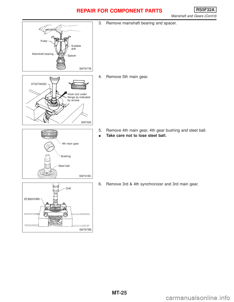
3. Remove mainshaft bearing and spacer.
4. Remove 5th main gear.
5. Remove 4th main gear, 4th gear bushing and steel ball.
ITake care not to lose steel ball.
6. Remove 3rd & 4th synchronizer and 3rd main gear.
SMT677B Puller
Mainshaft bearingSuitable
drift
Spacer
SMT593 ST22730000
Hook tool under
flange as indicated
by arrows
SMT418C 4th main gear
Bushing
Steel ball
SMT679B Drift
REPAIR FOR COMPONENT PARTSRS5F32A
Mainshaft and Gears (Cont'd)
MT-25
Page 2103 of 2267
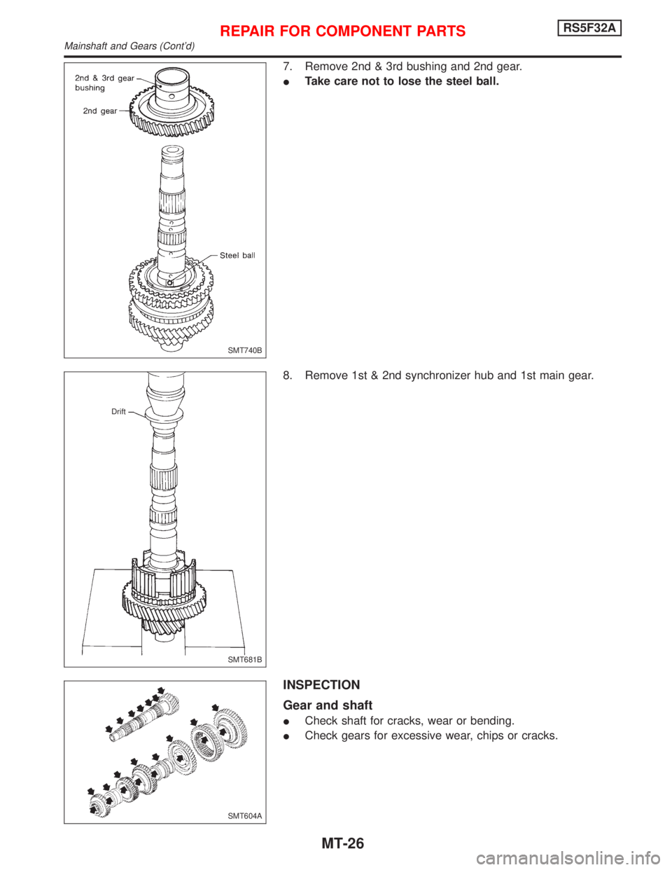
7. Remove 2nd & 3rd bushing and 2nd gear.
ITake care not to lose the steel ball.
8. Remove 1st & 2nd synchronizer hub and 1st main gear.
INSPECTION
Gear and shaft
ICheck shaft for cracks, wear or bending.
ICheck gears for excessive wear, chips or cracks.
SMT740B
SMT681B Drift
SMT604A
REPAIR FOR COMPONENT PARTSRS5F32A
Mainshaft and Gears (Cont'd)
MT-26
Page 2104 of 2267
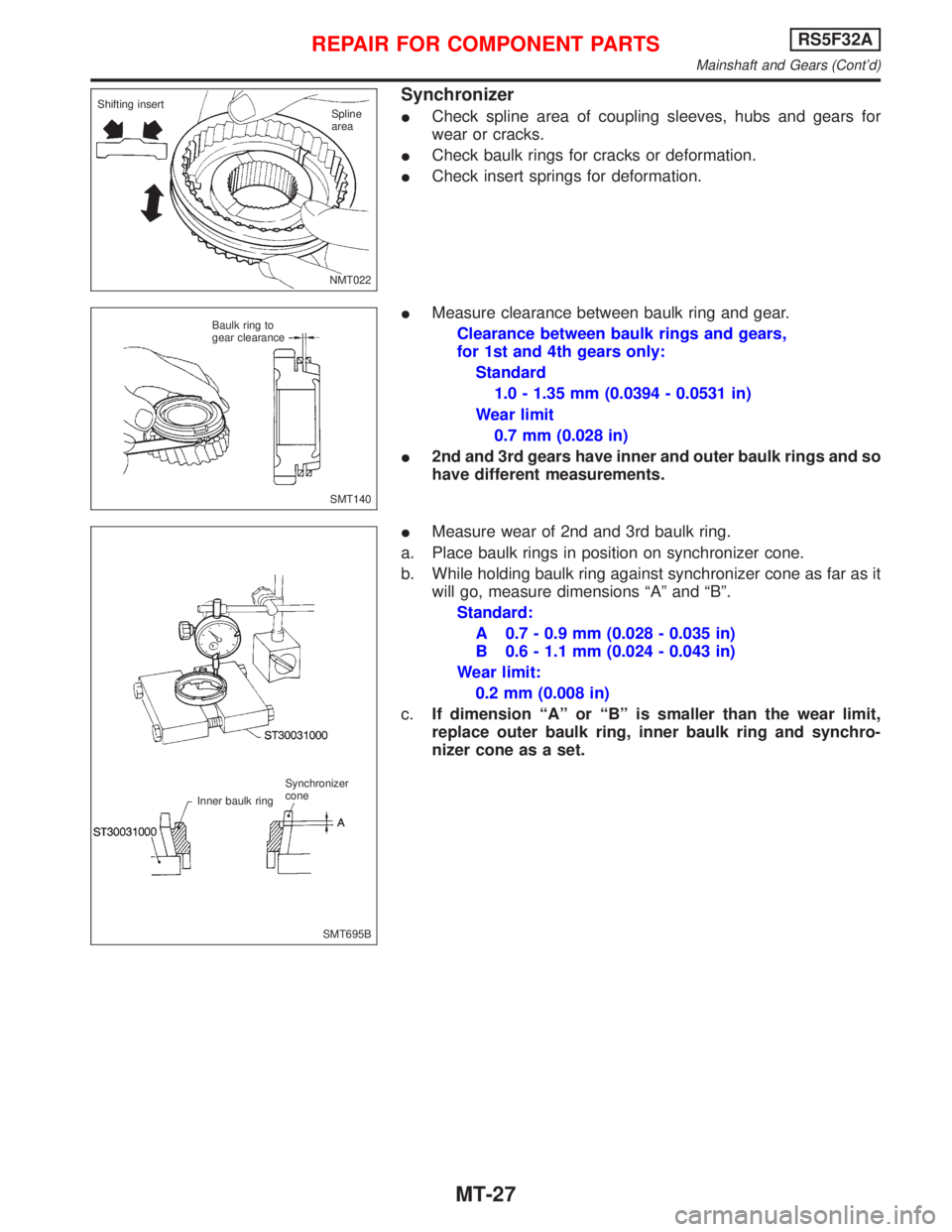
Synchronizer
ICheck spline area of coupling sleeves, hubs and gears for
wear or cracks.
ICheck baulk rings for cracks or deformation.
ICheck insert springs for deformation.
IMeasure clearance between baulk ring and gear.
Clearance between baulk rings and gears,
for 1st and 4th gears only:
Standard
1.0 - 1.35 mm (0.0394 - 0.0531 in)
Wear limit
0.7 mm (0.028 in)
I2nd and 3rd gears have inner and outer baulk rings and so
have different measurements.
IMeasure wear of 2nd and 3rd baulk ring.
a. Place baulk rings in position on synchronizer cone.
b. While holding baulk ring against synchronizer cone as far as it
will go, measure dimensions ªAº and ªBº.
Standard:
A 0.7 - 0.9 mm (0.028 - 0.035 in)
B 0.6 - 1.1 mm (0.024 - 0.043 in)
Wear limit:
0.2 mm (0.008 in)
c.If dimension ªAº or ªBº is smaller than the wear limit,
replace outer baulk ring, inner baulk ring and synchro-
nizer cone as a set.
NMT022 Shifting insert
Spline
area
SMT140 Baulk ring to
gear clearance
SMT695B Synchronizer
cone
Inner baulk ring
REPAIR FOR COMPONENT PARTSRS5F32A
Mainshaft and Gears (Cont'd)
MT-27
Page 2105 of 2267
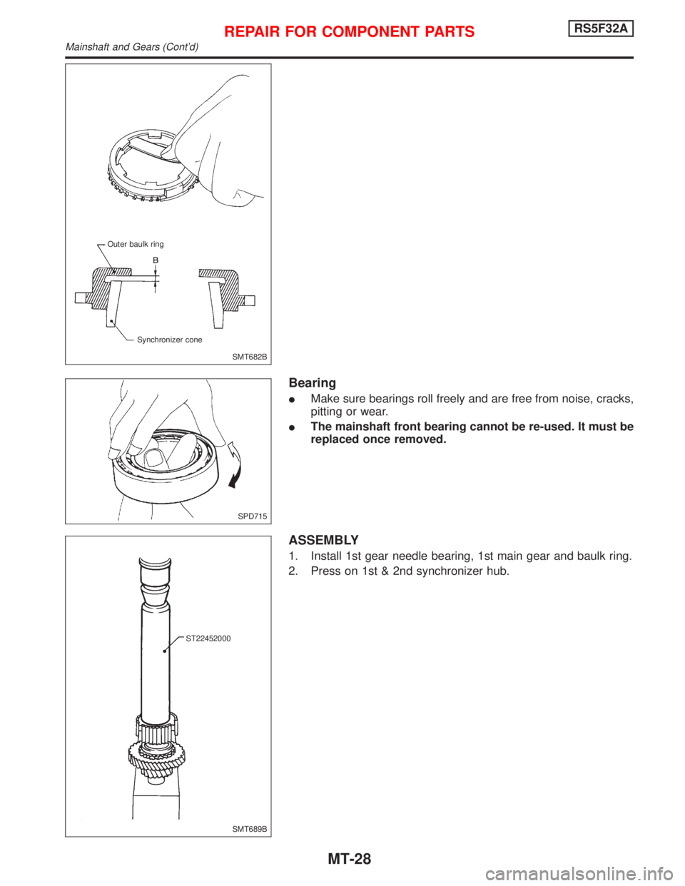
Bearing
IMake sure bearings roll freely and are free from noise, cracks,
pitting or wear.
IThe mainshaft front bearing cannot be re-used. It must be
replaced once removed.
ASSEMBLY
1. Install 1st gear needle bearing, 1st main gear and baulk ring.
2. Press on 1st & 2nd synchronizer hub.
SMT682B Outer baulk ring
Synchronizer cone
SPD715
SMT689B ST22452000
REPAIR FOR COMPONENT PARTSRS5F32A
Mainshaft and Gears (Cont'd)
MT-28
Page 2106 of 2267
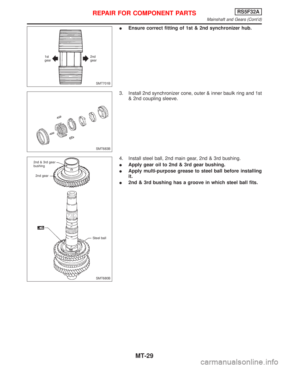
IEnsure correct fitting of 1st & 2nd synchronizer hub.
3. Install 2nd synchronizer cone, outer & inner baulk ring and 1st
& 2nd coupling sleeve.
4. Install steel ball, 2nd main gear, 2nd & 3rd bushing.
IApply gear oil to 2nd & 3rd gear bushing.
IApply multi-purpose grease to steel ball before installing
it.
I2nd & 3rd bushing has a groove in which steel ball fits.
SMT701B 2nd
gear 1st
gear
SMT683B
SMT680B 2nd & 3rd gear
bushing
2nd gear
Steel ball
REPAIR FOR COMPONENT PARTSRS5F32A
Mainshaft and Gears (Cont'd)
MT-29
Page 2107 of 2267
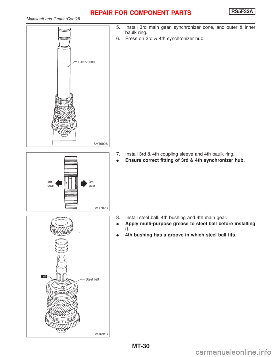
5. Install 3rd main gear, synchronizer cone, and outer & inner
baulk ring.
6. Press on 3rd & 4th synchronizer hub.
7. Install 3rd & 4th coupling sleeve and 4th baulk ring.
IEnsure correct fitting of 3rd & 4th synchronizer hub.
8. Install steel ball, 4th bushing and 4th main gear.
IApply multi-purpose grease to steel ball before installing
it.
I4th bushing has a groove in which steel ball fits.
SMT690B ST37750000
SMT702B 3rd
gear 4th
gear
SMT691B Steel ball
REPAIR FOR COMPONENT PARTSRS5F32A
Mainshaft and Gears (Cont'd)
MT-30
Page 2108 of 2267
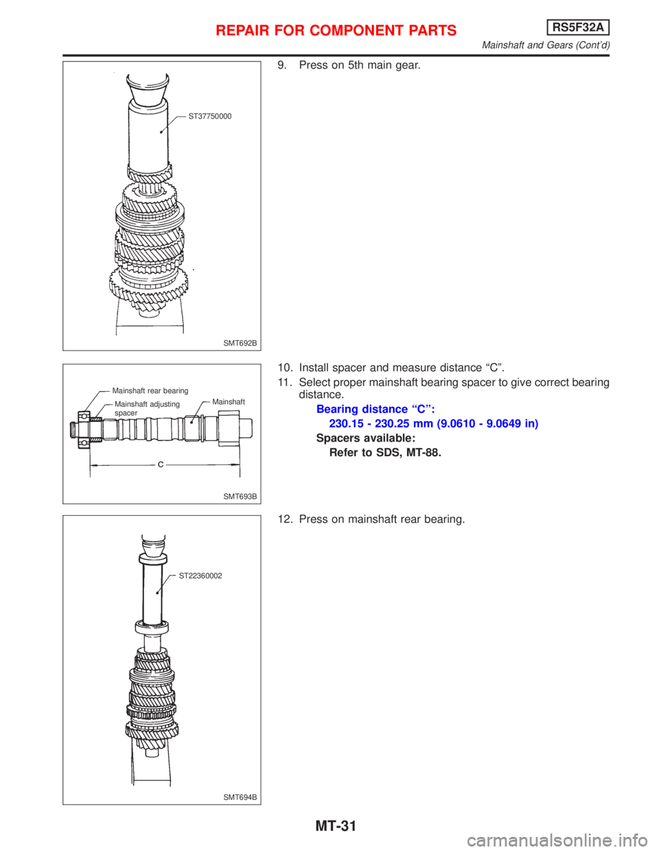
9. Press on 5th main gear.
10. Install spacer and measure distance ªCº.
11. Select proper mainshaft bearing spacer to give correct bearing
distance.
Bearing distance ªCº:
230.15 - 230.25 mm (9.0610 - 9.0649 in)
Spacers available:
Refer to SDS, MT-88.
12. Press on mainshaft rear bearing.
SMT692B ST37750000
SMT693B Mainshaft rear bearing
Mainshaft
Mainshaft adjusting
spacer
SMT694B ST22360002
REPAIR FOR COMPONENT PARTSRS5F32A
Mainshaft and Gears (Cont'd)
MT-31
Page 2109 of 2267
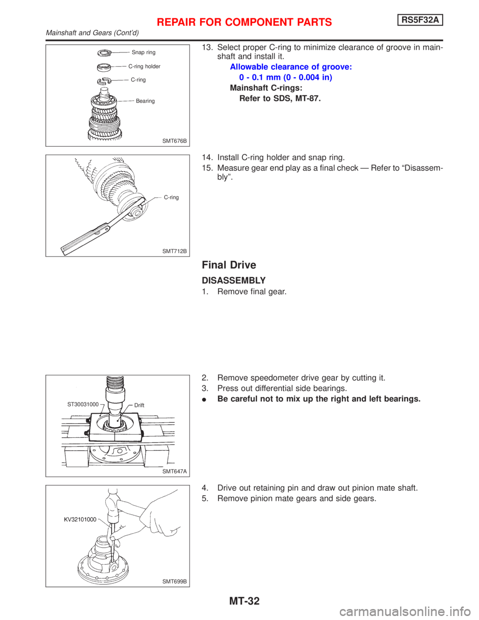
13. Select proper C-ring to minimize clearance of groove in main-
shaft and install it.
Allowable clearance of groove:
0 - 0.1 mm (0 - 0.004 in)
Mainshaft C-rings:
Refer to SDS, MT-87.
14. Install C-ring holder and snap ring.
15. Measure gear end play as a final check Ð Refer to ªDisassem-
blyº.
Final Drive
DISASSEMBLY
1. Remove final gear.
2. Remove speedometer drive gear by cutting it.
3. Press out differential side bearings.
IBe careful not to mix up the right and left bearings.
4. Drive out retaining pin and draw out pinion mate shaft.
5. Remove pinion mate gears and side gears.
SMT676B Snap ring
C-ring holder
C-ring
Bearing
SMT712BC-ring
SMT647A Drift ST30031000
SMT699B
REPAIR FOR COMPONENT PARTSRS5F32A
Mainshaft and Gears (Cont'd)
MT-32
Page 2110 of 2267
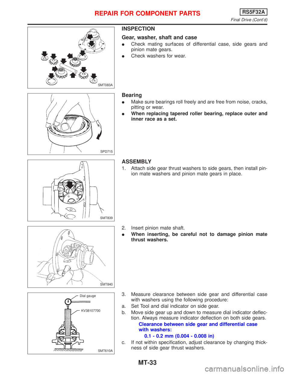
INSPECTION
Gear, washer, shaft and case
ICheck mating surfaces of differential case, side gears and
pinion mate gears.
ICheck washers for wear.
Bearing
IMake sure bearings roll freely and are free from noise, cracks,
pitting or wear.
IWhen replacing tapered roller bearing, replace outer and
inner race as a set.
ASSEMBLY
1. Attach side gear thrust washers to side gears, then install pin-
ion mate washers and pinion mate gears in place.
2. Insert pinion mate shaft.
IWhen inserting, be careful not to damage pinion mate
thrust washers.
3. Measure clearance between side gear and differential case
with washers using the following procedure:
a. Set Tool and dial indicator on side gear.
b. Move side gear up and down to measure dial indicator deflec-
tion. Always measure indicator deflection on both side gears.
Clearance between side gear and differential case
with washers:
0.1 - 0.2 mm (0.004 - 0.008 in)
c. If not within specification, adjust clearance by changing thick-
ness of side gear thrust washers.
SMT083A
SPD715
SMT839
SMT840
SMT610A Dial gauge
KV38107700
REPAIR FOR COMPONENT PARTSRS5F32A
Final Drive (Cont'd)
MT-33
Trending: change wheel, oil change, air condition, hood release, battery, differential, open gas tank
