fuel pump NISSAN PRIMERA 1999 Electronic Owner's Manual
[x] Cancel search | Manufacturer: NISSAN, Model Year: 1999, Model line: PRIMERA, Model: NISSAN PRIMERA 1999Pages: 2267, PDF Size: 35.74 MB
Page 378 of 2267

DIAGNOSTIC PROCEDURE
INSPECTION START
CHECK FOR AIR IN FUEL FILTER.
1. Move priming pump up and down to
purge air from fuel filter.
2. Perform ªDIAGNOSTIC TROUBLE
CODE CONFIRMATION PROCE-
DUREº.
CHECK POWER SUPPLY.
1. Turn ignition switch to ªLOCKº posi-
tion.
2. Disconnect injection timing control
valve harness connector.
3. Turn ignition switch to ªONº position.
4. Check voltage between injection tim-
ing control valve connector terminal
p3and ground with CONSULT-II or
tester.
Voltage: Battery voltage
OK
ENG
Check the following:
lHarness connectors
E89,F96
lElectronic injection
pump harness connec-
tor
F49
l15A fuse
lHarness for open or
short-circuit between
injection timing control
valve harness connec-
tor and ECM relay.
If NG, repair harness or
connectors.
CHECK OUTPUT SIGNAL CIRCUIT.
1. Turn ignition switch to ªLOCKº posi-
tion.
2. Disconnect ECM harness connector.
3. Check harness continuity between
injection timing control valve connec-
tor terminal
p2and ECM terminals
202.
Continuity should exist.
If OK, check harness for short-cir-
cuit.
OK
ENG
Check the following:
lElectronic injection
pump harness connec-
tor
F49
lHarness for open or
short-circuit between
injection timing control
valve and ECM.
If NG, repair harness or
connectors.
pA
SEF671S
Priming pump
NEF804
Fuel injection timing
control valve harness
connector
NEF201A
Injection timing control
valve harness connector
NEF202A
Injection timing control
valve harness connector
H
H
H
H
TROUBLE DIAGNOSIS 6CD20T
Injection Timing Control Valve (Cont'd)
EC-84
Page 393 of 2267

DIAGNOSTIC PROCEDURE
INSPECTION START
CHECK FOR AIR IN FUEL FILTER.
1. Move priming pump up and down to
purge air from fuel filter.
2. Perform ªDIAGNOSTIC TROUBLE
CODE CONFIRMATION PROCE-
DUREº.
CHECK INPUT SIGNAL CIRCUIT.
1. Turn ignition switch to ªLOCKº posi-
tion.
2. Disconnect ECM harness connector
and needle lift sensor harness con-
nector.
3. Check harness continuity between
needle lift sensor connector terminal
p1and ECM connector terminal
345.
Continuity should exist.
If OK, check harness for short-cir-
cuit.
OK
ENG
Repair harness or con-
nectors.
CHECK GROUND CIRCUIT.
Check resistance between needle lift
sensor connector terminal
p2and
ECM connector terminal
333.
Continuity should exist.
If OK, check harness for short-circuit.
OK
ENG
Repair harness or con-
nectors.
CHECK NO. 1 INJECTION NOZZLE
FOR CLOGGING.
Refer to spray pattern test of ªINJEC-
TION NOZZLEº.
If NG, replace No. 1 injection nozzle.
Disconnect and reconnect harness
connectors in the circuit. Then retest.
Trouble is not fixed
Check ECM pin terminals for damage
and check the connection of ECM har-
ness connector. Reconnect ECM har-
ness connector and retest.
INSPECTION END
SEF671S
Priming pump
SEF606S
Needle lift sensor
harness connector
NEF206A
Needle lift sensor
connector
NEF205A
Needle lift sensor
connector
H
H
H
H
H
H
H
TROUBLE DIAGNOSIS 9CD20T
Needle Lift Sensor (NLS) (Cont'd)
EC-99
Page 395 of 2267

YEC807
BATTERY
Refer to EL-POWER.
: Detectable line for DTC
: Non-detectable line for DTC
INJECTION PUMP
(FUEL CUT SOLE-
NOID VALVE)
ENGINE
CONTROL
MODULE
RELAY
ECM
TROUBLE DIAGNOSIS 10CD20T
Fuel Cut Solenoid Valve (Cont'd)
EC-101
Page 396 of 2267

DIAGNOSTIC PROCEDURE
INSPECTION START
CHECK MAIN POWER SUPPLY.
Check power supply. Refer to
EC-CD-59.
CHECK OUTPUT SIGNAL CIRCUIT.
1. Turn ignition switch to ªONº
position.
2. Select ªFUEL CUT SOL/Vº in
ªACTIVE TESTº mode with
CONSULT-II.
3. Touch ªONº and ªOFFº alter-
nately.
4. Check that operating sound is
emitted.
---------------------------------------------------------------------------------------------------------------------------------OR---------------------------------------------------------------------------------------------------------------------------------
1. Turn ignition switch to ªLOCKº
position.
2. Disconnect ECM harness con-
nector and electronic injection
pump harness connector.
3. Check harness continuity
between fuel cut solenoid valve
connector terminal
p1and
ECM connector terminal
349.
Continuity should exist.
If OK, check harness for short.
OK
ENG
Repair harness or con-
nectors.
CHECK COMPONENT
(Fuel cut solenoid valve).
Refer to ªCOMPONENT INSPECTIONº
on next page.
OK
ENG
Replace fuel cut solenoid
valve.
Disconnect and reconnect harness
connectors in the circuit. Then retest.
Trouble is not fixed.
Check ECM pin terminals for damage
and check the connection of ECM har-
ness connector. Reconnect ECM har-
ness connector and retest.
INSPECTION END
NEF815
.Electronic injection
pump harness connector
(Fuel cut solenoid valve)
C2FCS01
NEF226A
Electronic injection
pump harness con-
nection
H
H
H
H
H
H
TROUBLE DIAGNOSIS 10CD20T
Fuel Cut Solenoid Valve (Cont'd)
EC-102
Page 398 of 2267

Fuel Temperature Sensor (FTS)
The fuel temperature sensor is used to detect the fuel tempera-
ture in the injection pump. The sensor modifies a voltage signal
from the ECM. The modified signal returns to the ECM as the fuel
temperature input. The sensor uses a thermistor which is sensi-
tive to the change in temperature. The electrical resistance of the
thermistor decreases as temperature increases.
The sensor is built into the inside electrical circuit of the injection
pump.
Malfunction is detected when ...Check Items
(Possible Cause)
lAn excessively high or low voltage from the sensor is
detected by ECM.lHarness or connectors
(The sensor circuit is open or shorted.)
lFuel temperature sensor
DIAGNOSTIC TROUBLE CONFIRMATION
PROCEDURE
1) Turn ignition switch to ªONº position.
2) Select ªDATA MONITORº mode with CONSULT-II.
3) Wait at least 5 seconds.
TROUBLE DIAGNOSIS 11CD20T
EC-104
Page 399 of 2267

YEC808
INJECTION PUMP
(FUEL TEMPERATURE
SENSOR)
: Detectable line for DTC
: Non-detectable line for DTC
ECM
TROUBLE DIAGNOSIS 11CD20T
Fuel Temperature Sensor (FTS) (Cont'd)
EC-105
Page 400 of 2267

DIAGNOSTIC PROCEDURE
INSPECTION START
CHECK POWER SUPPLY.
1. Turn ignition switch to ªLOCKº posi-
tion.
2. Disconnect fuel temperature sensor
harness connector.
3. Turn ignition switch to ªONº position.
4. Check voltage between injection
pump connector terminal
p6and
ground with CONSULT-II or voltage
tester.
Voltage:
Approximately 5V
OK
ENG
Repair harness or con-
nectors.
CHECK GROUND CIRCUIT.
1. Turn ignition switch to ªLOCKº posi-
tion.
2. Check harness continuity between
injection pump connector terminal
p5and ECM connector terminals
335,436.
Continuity should exist.
If OK, check harness for short-cir-
cuit.
OK
ENG
Repair harness or con-
nectors.
CHECK COMPONENT
(Fuel temperature sensor).
Refer to ªCOMPONENT INSPECTIONº
on next page.
OK
ENG
Have the injection pump
assembly serviced by an
authorised service repre-
sentative.
Disconnect and reconnect harness
connectors in the circuits. Then retest.
Trouble is not fixed.
Check ECM pin terminals for damage
and check the connection of ECM har-
ness connector. Reconnect ECM har-
ness connector and retest.
INSPECTION END
NEF818
.Electronic injection
pump harness connector
(Fuel temperature sensor)
NEF819
Injection pump
connector
NEF208A
Injection pump
connector
F50
H
H
H
H
H
H
TROUBLE DIAGNOSIS 11CD20T
Fuel Temperature Sensor (FTS) (Cont'd)
EC-106
Page 401 of 2267
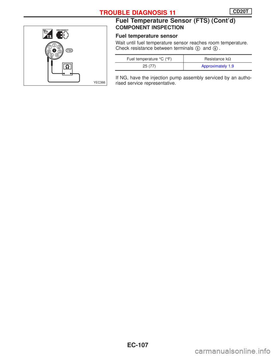
COMPONENT INSPECTION
Fuel temperature sensor
Wait until fuel temperature sensor reaches room temperature.
Check resistance between terminals
p5andp6.
Fuel temperature ÉC (ÉF) Resistance kW
25 (77)Approximately 1.9
If NG, have the injection pump assembly serviced by an autho-
rised service representative.YEC366
TROUBLE DIAGNOSIS 11CD20T
Fuel Temperature Sensor (FTS) (Cont'd)
EC-107
Page 441 of 2267
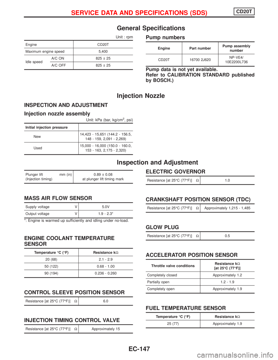
General Specifications
Unit : rpm
Engine CD20T
Maximum engine speed 5,400
Idle speedA/C ON 825 25
A/C OFF 825 25
Pump numbers
Engine Part numberPump assembly
number
CD20T 16700 2J620NP-VE4/
10E2200L736
Pump data is not yet available.
Refer to CALIBRATION STANDARD published
by BOSCH.)
Injection Nozzle
INSPECTION AND ADJUSTMENT
Injection nozzle assembly
Unit: kPa (bar, kg/cm2, psi)
Initial injection pressure
New14,423 - 15,651 (144.2 - 156.5,
148 - 159, 2,091 - 2,269)
Used15,000 - 16,000 (150.0 - 160.0,
153 - 163, 2,175 - 2,320)
Inspection and Adjustment
Plunger lift mm (in)
(Injection timing)0.89 0.08
at plunger lift timing mark
MASS AIR FLOW SENSOR
Supply voltage V 5.0V
Output voltage V 1.9 - 2.3*
*: Engine is warmed up sufficiently and idling under no-load.
ENGINE COOLANT TEMPERATURE
SENSOR
Temperature ÉC (ÉF) Resistance kW
20 (68) 2.1 - 2.9
50 (122) 0.68 - 1.00
90 (194) 0.236 - 0.260
CONTROL SLEEVE POSITION SENSOR
Resistance [at 25ÉC (77ÉF)]W6.0
INJECTION TIMING CONTROL VALVE
Resistance [at 25ÉC (77ÉF)]WApproximately 15
ELECTRIC GOVERNOR
Resistance [at 25ÉC (77ÉF)]W1.0
CRANKSHAFT POSITION SENSOR (TDC)
Resistance [at 25ÉC (77ÉF)]WApproximately 1,215 - 1,485
GLOW PLUG
Resistance [at 25ÉC (77ÉF)]W0.5
ACCELERATOR POSITION SENSOR
Throttle valve conditionsResistance kW
[at 25ÉC (77ÉF)]
Completely closed Approximately 1.2
Partially open 1.2 - 1.9
Completely open Approximately 1.9
FUEL TEMPERATURE SENSOR
Temperature ÉC (ÉF) Resistance kW
25 (77) Approximately 1.9
SERVICE DATA AND SPECIFICATIONS (SDS)CD20T
EC-147
Page 447 of 2267
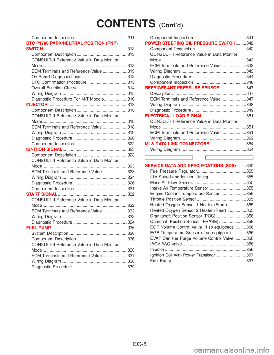
Component Inspection ............................................. 311
DTC P1706 PARK/NEUTRAL POSITION (PNP)
SWITCH.......................................................................313
Component Description ...........................................313
CONSULT-II Reference Value in Data Monitor
Mode ........................................................................313
ECM Terminals and Reference Value .....................313
On Board Diagnosis Logic.......................................313
DTC Confirmation Procedure ..................................313
Overall Function Check ...........................................314
Wiring Diagram ........................................................315
Diagnostic Procedure For M/T Models....................316
INJECTOR...................................................................318
Component Description ...........................................318
CONSULT-II Reference Value in Data Monitor
Mode ........................................................................318
ECM Terminals and Reference Value .....................318
Wiring Diagram ........................................................319
Diagnostic Procedure ..............................................320
Component Inspection .............................................322
IGNITION SIGNAL.......................................................323
Component Description ...........................................323
CONSULT-II Reference Value in Data Monitor
Mode ........................................................................323
ECM Terminals and Reference Value .....................323
Wiring Diagram ........................................................324
Diagnostic Procedure ..............................................326
Component Inspection .............................................331
START SIGNAL...........................................................332
CONSULT-II Reference Value in Data Monitor
Mode ........................................................................332
ECM Terminals and Reference Value .....................332
Wiring Diagram ........................................................333
Diagnostic Procedure ..............................................334
FUEL PUMP.................................................................336
System Description ..................................................336
Component Description ...........................................336
CONSULT-II Reference Value in Data Monitor
Mode ........................................................................336
ECM Terminals and Reference Value .....................337
Wiring Diagram ........................................................338
Diagnostic Procedure ..............................................339Component Inspection .............................................341
POWER STEERING OIL PRESSURE SWITCH.........342
Component Description ...........................................342
CONSULT-II Reference Value in Data Monitor
Mode ........................................................................342
ECM Terminals and Reference Value .....................342
Wiring Diagram ........................................................343
Diagnostic Procedure ..............................................344
Component Inspection .............................................346
REFRIGERANT PRESSURE SENSOR......................347
Description ...............................................................347
ECM Terminals and Reference Value .....................347
Wiring Diagram ........................................................348
Diagnostic Procedure ..............................................349
ELECTRICAL LOAD SIGNAL.....................................351
CONSULT-II Reference Value in Data Monitor
Mode ........................................................................351
ECM Terminals and Reference Value .....................351
Wiring Diagram ........................................................352
MI & DATA LINK CONNECTORS...............................354
Wiring Diagram ........................................................354
SERVICE DATA AND SPECIFICATIONS (SDS)........355
Fuel Pressure Regulator..........................................355
Idle Speed and Ignition Timing ................................355
Mass Air Flow Sensor..............................................355
Intake Air Temperature Sensor ................................355
Engine Coolant Temperature Sensor ......................355
Throttle Position Sensor ..........................................355
Heated Oxygen Sensor 1 Heater (Front) ................355
Heated Oxygen Sensor 2 Heater (Rear).................355
Crankshaft Position Sensor (POS) ..........................356
Camshaft Position Sensor (PHASE) .......................356
EGR Volume Control Valve (If so equipped)...........356
EGR Temperature Sensor (If so equipped).............356
EVAP Canister Purge Volume Control Valve ..........356
IACV-AAC Valve ......................................................356
Injector .....................................................................356
Ignition Coil with Power Transistor ..........................357
Fuel Pump ...............................................................357
CONTENTS(Cont'd)
EC-5