fuel pump NISSAN PRIMERA 1999 Electronic Workshop Manual
[x] Cancel search | Manufacturer: NISSAN, Model Year: 1999, Model line: PRIMERA, Model: NISSAN PRIMERA 1999Pages: 2267, PDF Size: 35.74 MB
Page 783 of 2267
8 CHECK FUEL PUMP RELAY
Refer to ªComponent Inspectionº, EC-QG-341.
OK or NG
OK©GO TO 9.
NG©Replace fuel pump relay.
9 CHECK FUEL PUMP
Refer to ªComponent Inspectionº, EC-QG-341.
OK or NG
OK©GO TO 10.
NG©Replace fuel pump.
10 CHECK INTERMITTENT INCIDENT
Perform ªTROUBLE DIAGNOSIS FOR INTERMITTENT INCIDENTº, EC-QG-102.
©INSPECTION END
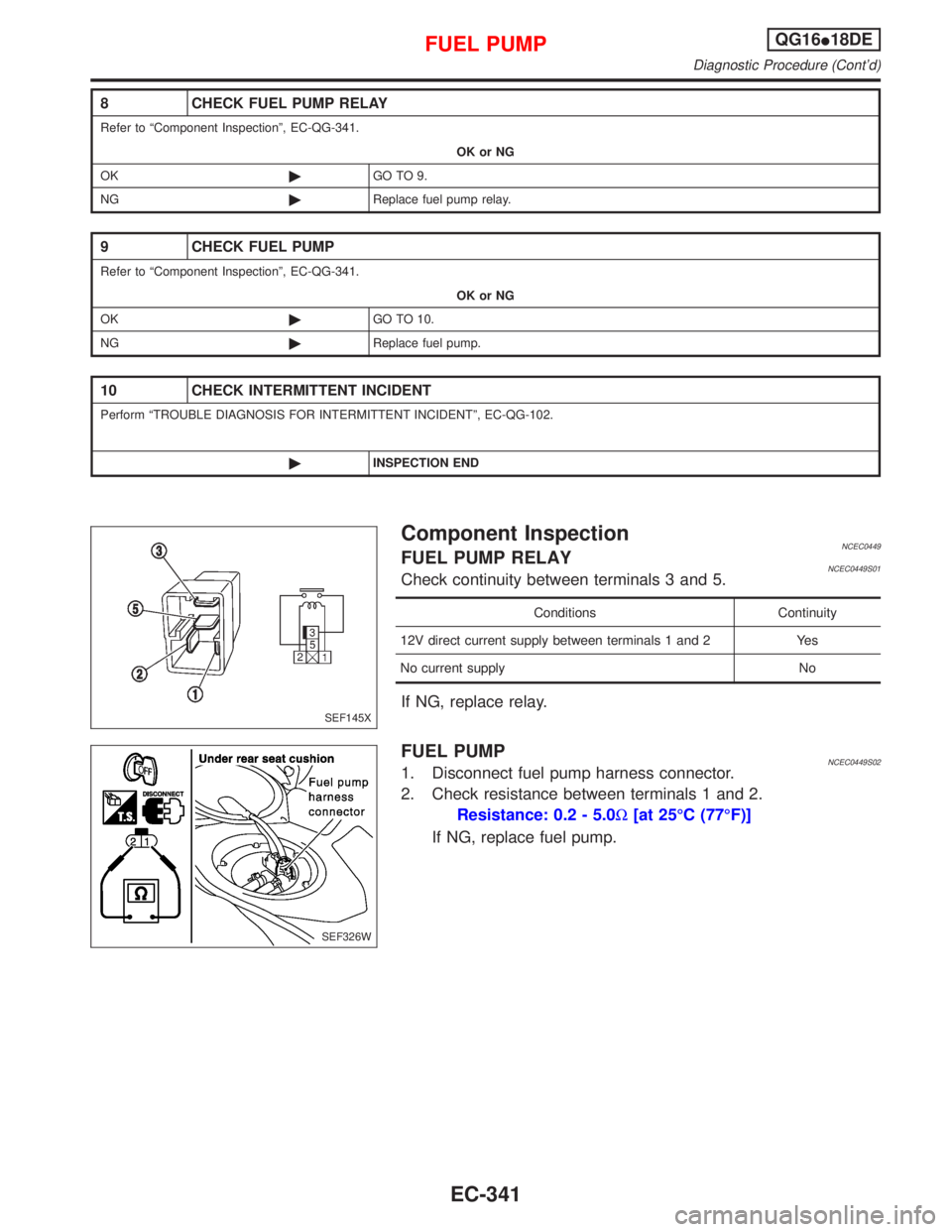
Component InspectionNCEC0449FUEL PUMP RELAYNCEC0449S01Check continuity between terminals 3 and 5.
Conditions Continuity
12V direct current supply between terminals 1 and 2 Yes
No current supply No
If NG, replace relay.
FUEL PUMPNCEC0449S021. Disconnect fuel pump harness connector.
2. Check resistance between terminals 1 and 2.
Resistance: 0.2 - 5.0W[at 25ÉC (77ÉF)]
If NG, replace fuel pump.
SEF145X
SEF326W
FUEL PUMPQG16I18DE
Diagnostic Procedure (Cont'd)
EC-341
Page 799 of 2267

Ignition Coil with Power TransistorNCEC0561
Terminal No. (Polarity) ResistanceW[at 25ÉC (77ÉF)]
3 (+) - 2 (þ) Except 0 or¥
1 (+) - 3 (þ)
Except 0
1 (+) - 2 (þ)
Fuel PumpNCEC0473
Resistance [at 25ÉC (77ÉF)]W0.2 - 5.0
SERVICE DATA AND SPECIFICATIONS (SDS)
Ignition Coil with Power Transistor
EC-357
Page 805 of 2267
CONSULT-II Reference Value in Data Monitor
Mode ........................................................................306
ECM Terminals and Reference Value .....................306
Wiring Diagram ........................................................308
Diagnostic Procedure ..............................................309
Component Inspection .............................................310
START SIGNAL...........................................................312
CONSULT-II Reference Value in Data Monitor
Mode ........................................................................312
ECM Terminals and Reference Value .....................312
Wiring Diagram ........................................................313
Diagnostic Procedure ..............................................314
FUEL PUMP.................................................................316
System Description ..................................................316
Component Description ...........................................316
CONSULT-II Reference Value in Data Monitor
Mode ........................................................................316
ECM Terminals and Reference Value .....................316
Wiring Diagram ........................................................317
Diagnostic Procedure ..............................................318
Component Inspection .............................................320
POWER STEERING OIL PRESSURE SWITCH.........321
Component Description ...........................................321
CONSULT-II Reference Value in Data Monitor
Mode ........................................................................321
ECM Terminals and Reference Value .....................321
Wiring Diagram ........................................................322Diagnostic Procedure ..............................................323
Component Inspection .............................................324
ELECTRICAL LOAD SIGNAL.....................................325
CONSULT-II Reference Value in Data Monitor
Mode ........................................................................325
ECM Terminals and Reference Value .....................325
Wiring Diagram ........................................................326
MI & DATA LINK CONNECTORS..............................329
Wiring Diagram ........................................................329
SERVICE DATA AND SPECIFICATIONS (SDS).......330
Fuel Pressure Regulator..........................................330
Idle Speed and Ignition Timing ................................330
Ignition Coil ..............................................................330
Mass Air Flow Sensor..............................................330
Engine Coolant Temperature Sensor ......................330
Fuel Pump ...............................................................330
IACV-AAC Valve ......................................................330
Injector .....................................................................330
Throttle Position Sensor ..........................................331
Heated Oxygen Sensor 1 (Front) Heater ................331
Intake Air Temperature Sensor ................................331
EVAP Canister Purge Volume Control Valve ..........331
Heated Oxygen Sensor 1 (Rear) Heater.................331
Crankshaft Position Sensor (OBD)..........................331
CONTENTS(Cont'd)
EC-5
Page 817 of 2267
SEF188X ECM
ECM harness
connectorGlove box
View from under the vehicleFront exhaust tube
Coolant temperature
sensor harness connector
Front
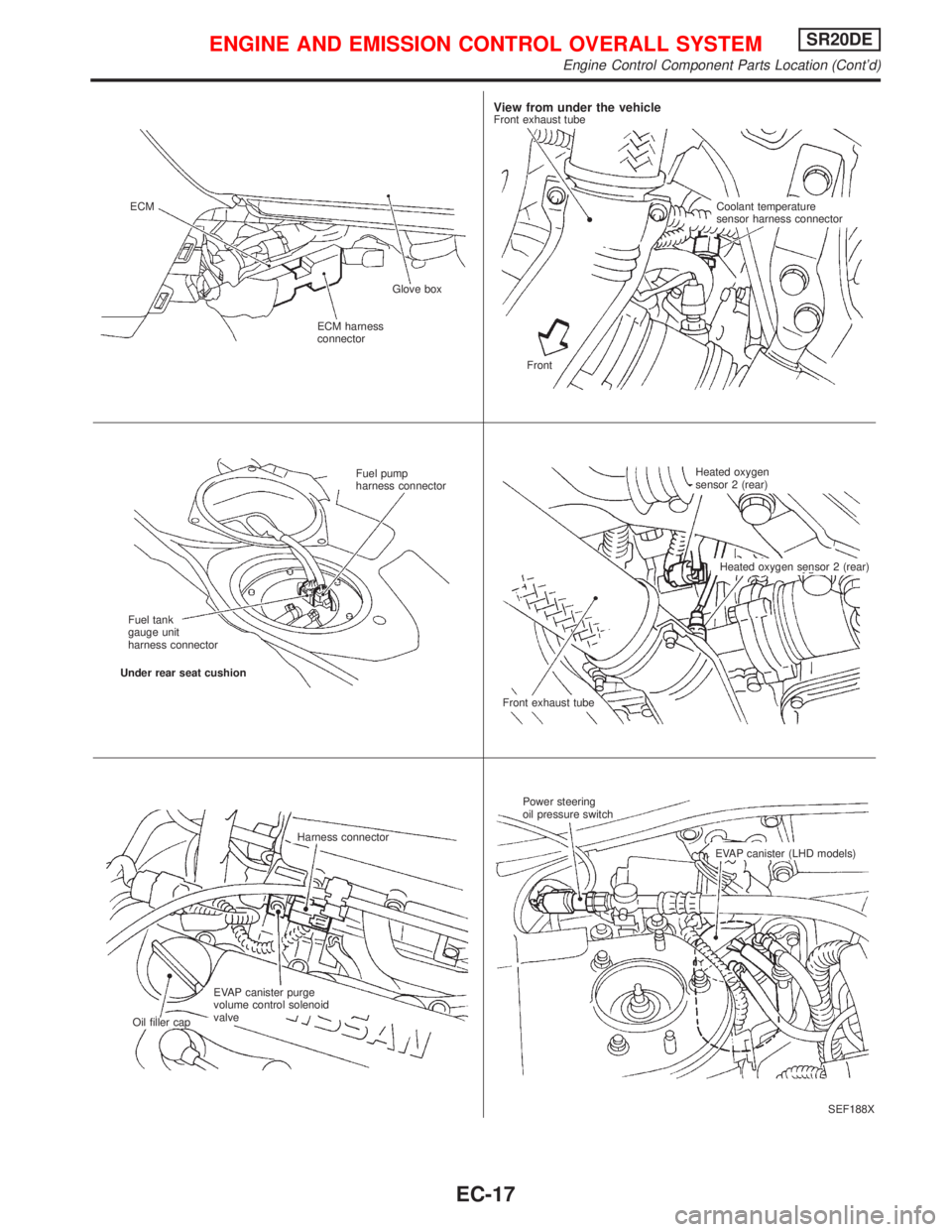
Fuel pump
harness connector
Fuel tank
gauge unit
harness connector
Under rear seat cushion
Front exhaust tubeHeated oxygen
sensor 2 (rear)
Heated oxygen sensor 2 (rear)
Harness connector
EVAP canister purge
volume control solenoid
valve
Oil filler capPower steering
oil pressure switch
EVAP canister (LHD models)
ENGINE AND EMISSION CONTROL OVERALL SYSTEMSR20DE
Engine Control Component Parts Location (Cont'd)
EC-17
Page 822 of 2267
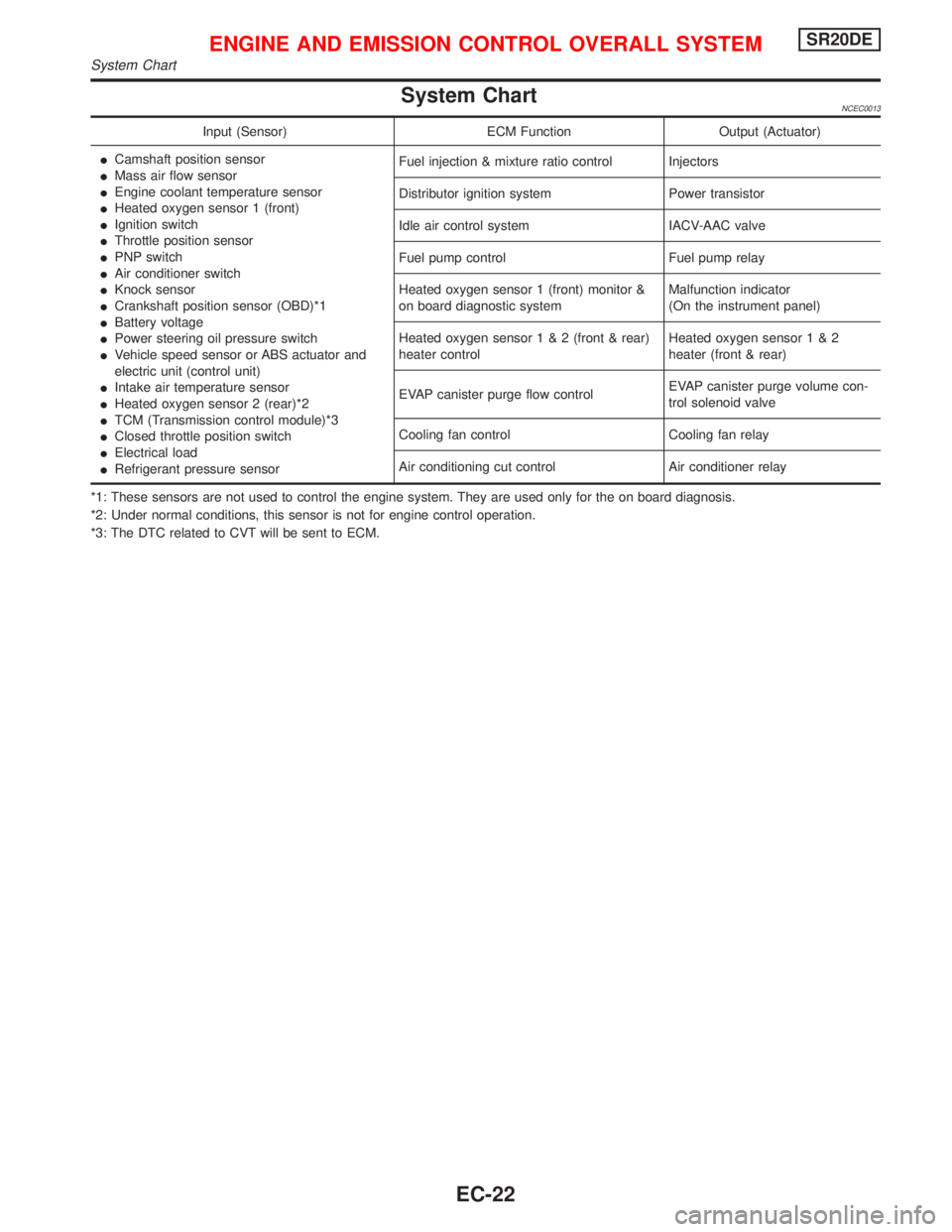
System ChartNCEC0013
Input (Sensor) ECM Function Output (Actuator)
ICamshaft position sensor
IMass air flow sensor
IEngine coolant temperature sensor
IHeated oxygen sensor 1 (front)
IIgnition switch
IThrottle position sensor
IPNP switch
IAir conditioner switch
IKnock sensor
ICrankshaft position sensor (OBD)*1
IBattery voltage
IPower steering oil pressure switch
IVehicle speed sensor or ABS actuator and
electric unit (control unit)
IIntake air temperature sensor
IHeated oxygen sensor 2 (rear)*2
ITCM (Transmission control module)*3
IClosed throttle position switch
IElectrical load
IRefrigerant pressure sensorFuel injection & mixture ratio control Injectors
Distributor ignition system Power transistor
Idle air control system IACV-AAC valve
Fuel pump control Fuel pump relay
Heated oxygen sensor 1 (front) monitor &
on board diagnostic systemMalfunction indicator
(On the instrument panel)
Heated oxygen sensor1&2(front & rear)
heater controlHeated oxygen sensor1&2
heater (front & rear)
EVAP canister purge flow controlEVAP canister purge volume con-
trol solenoid valve
Cooling fan control Cooling fan relay
Air conditioning cut control Air conditioner relay
*1: These sensors are not used to control the engine system. They are used only for the on board diagnosis.
*2: Under normal conditions, this sensor is not for engine control operation.
*3: The DTC related to CVT will be sent to ECM.
ENGINE AND EMISSION CONTROL OVERALL SYSTEMSR20DE
System Chart
EC-22
Page 831 of 2267
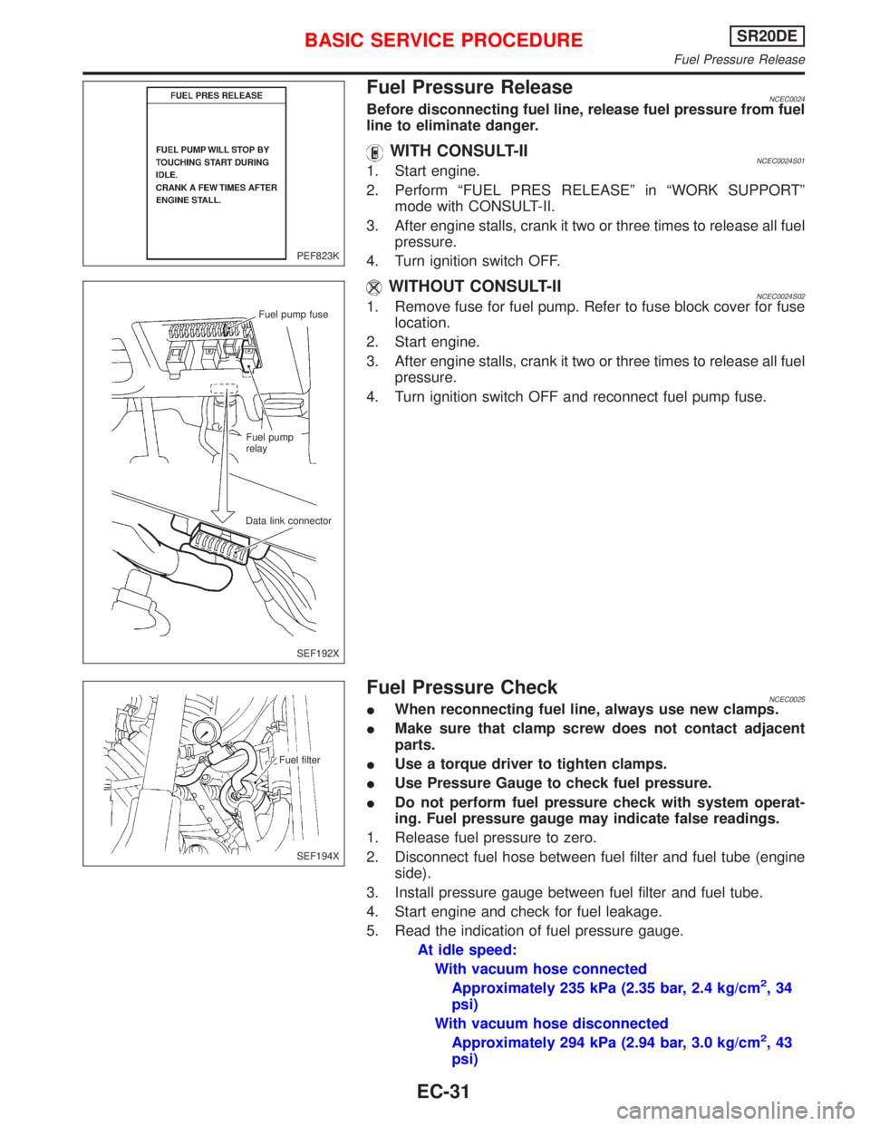
Fuel Pressure ReleaseNCEC0024Before disconnecting fuel line, release fuel pressure from fuel
line to eliminate danger.
WITH CONSULT-IINCEC0024S011. Start engine.
2. Perform ªFUEL PRES RELEASEº in ªWORK SUPPORTº
mode with CONSULT-II.
3. After engine stalls, crank it two or three times to release all fuel
pressure.
4. Turn ignition switch OFF.
WITHOUT CONSULT-IINCEC0024S021. Remove fuse for fuel pump. Refer to fuse block cover for fuse
location.
2. Start engine.
3. After engine stalls, crank it two or three times to release all fuel
pressure.
4. Turn ignition switch OFF and reconnect fuel pump fuse.
Fuel Pressure CheckNCEC0025IWhen reconnecting fuel line, always use new clamps.
IMake sure that clamp screw does not contact adjacent
parts.
IUse a torque driver to tighten clamps.
IUse Pressure Gauge to check fuel pressure.
IDo not perform fuel pressure check with system operat-
ing. Fuel pressure gauge may indicate false readings.
1. Release fuel pressure to zero.
2. Disconnect fuel hose between fuel filter and fuel tube (engine
side).
3. Install pressure gauge between fuel filter and fuel tube.
4. Start engine and check for fuel leakage.
5. Read the indication of fuel pressure gauge.
At idle speed:
With vacuum hose connected
Approximately 235 kPa (2.35 bar, 2.4 kg/cm
2,34
psi)
With vacuum hose disconnected
Approximately 294 kPa (2.94 bar, 3.0 kg/cm
2,43
psi)
PEF823K
Fuel pump fuse
Fuel pump
relay
Data link connector
SEF192X
Fuel filter
SEF194X
BASIC SERVICE PROCEDURESR20DE
Fuel Pressure Release
EC-31
Page 868 of 2267

CONSULT-II=NCEC0034CONSULT-II INSPECTION PROCEDURENCEC0034S011. Turn ignition switch OFF.
2. Connect ªCONSULT-IIº to data link connector.
(Data link connector is located behind the fuse box cover.)
3. Turn ignition switch ON.
4. Touch ªSTARTº.
5. Touch ªENGINEº.
6. Perform each diagnostic test mode according to each service
procedure.
For further information, see the CONSULT-II Operation
Manual.
SEF192X Fuel pump fuse
Fuel pump
relay
Data link connector
PBR455D
PEF895K
PEF216U
ON BOARD DIAGNOSTIC SYSTEM DESCRIPTIONSR20DE
CONSULT-II
EC-68
Page 870 of 2267

ItemDIAGNOSTIC TEST MODE
WORK
SUP-
PORTSELF-DIAGNOS-
TIC RESULTS
D ATA
MONI-
TORD ATA
MONI-
TOR
(SPEC)ACTIVE
TESTDTC
CONFIRMATION
DTC*1FREEZE
FRAME
DATA*2SRT
STATUSDTC
WORK
SUP-
PORT
ENGINE CONTROL COMPONENT PARTS
OUT-
PUTInjectors X X X
Power transistor (Ignition timing) XX
(Ignition
signal)XXX
IACV-AAC valve X X X X X
EVAP canister purge volume con-
trol solenoid valveX XXX
Air conditioner relay X X
Fuel pump relay X X X X
Heated oxygen sensor 1 (front)
heaterXXXX
Heated oxygen sensor 2 (rear)
heaterXXXX
Cooling fan X X X X
Calculated load value X X X
X: Applicable
*1: This item includes 1st trip DTCs.
*2: This mode includes 1st trip freeze frame data or freeze frame data. The items appear on CONSULT-II screen in freeze frame data
mode only if a 1st trip DTC or DTC is detected. For details, refer to EC-SR-50.
FUNCTIONNCEC0034S03
Diagnostic test mode Function
Work supportThis mode enables a technician to adjust some devices faster and more accurately by following the
indications on the CONSULT-II unit.
Self-diagnostic resultsSelf-diagnostic results such as 1st trip DTC, DTCs and 1st trip freeze frame data or freeze frame
data can be read and erased quickly.*1
Data monitor Input/Output data in the ECM can be read.
Data monitor (spec)Input/Output specifications of the basic fuel schedule, AFM, A/F feedback control value and the
other data monitor items can be read.
Active testDiagnostic Test Mode in which CONSULT-II drives some actuators apart from the ECMs and also
shifts some parameters in a specified range.
DTC confirmation The status of system monitoring tests and the self-diagnosis status/result can be confirmed.
ECM part number ECM part numbers can be read.
*1 The following emission-related diagnostic information is cleared when the ECM memory is erased.
1) Diagnostic trouble codes
2) 1st trip diagnostic trouble codes
3) Freeze frame data
4) 1st trip freeze frame data
5) System readiness test (SRT) codes
6) Test values
7) Distance traveled while MI is activated
8) Others
ON BOARD DIAGNOSTIC SYSTEM DESCRIPTIONSR20DE
CONSULT-II (Cont'd)
EC-70
Page 871 of 2267

WORK SUPPORT MODENCEC0034S04
WORK ITEM CONDITION USAGE
IGNITION TIMING ADJIIGNITION TIMING FEEDBACK CONTROL WILL BE
HELD BY TOUCHING ªSTARTº. AFTER DOING SO,
ADJUST IGNITION TIMING WITH A TIMING LIGHT BY
TURNING THE CAMSHAFT POSITION SENSOR.When adjusting initial ignition tim-
ing
FUEL PRESSURE RELEASEIFUEL PUMP WILL STOP BY TOUCHING ªSTARTº
DURING IDLING.
CRANK A FEW TIMES AFTER ENGINE STALLS.When releasing fuel pressure
from fuel line
TARGET IDLE RPM ADJIIDLE CONDITION When setting target idle speed
TARGET IGNITION TIMING ADJIIDLE CONDITION When adjusting target ignition
timing
After adjustment, confirm target
ignition timing with a timing light.
SELF DIAGNOSTIC MODENCEC0034S05DTC and 1st Trip DTCNCEC0034S0501Regarding items of ªDTC and 1st trip DTCº, refer to
ªTROUBLE DIAGNOSIS Ð INDEXº, EC-SR-6.
Freeze Frame Data and 1st Trip Freeze Frame DataNCEC0034S0502
Freeze frame data
item*Description
DIAG TROUBLE
CODE
[PXXXX]IEngine Control component part/control system has a trouble code, it is displayed as ªPXXXXº. [Refer
to ªAlphabetical & P No. Index for DTCº (EC-SR-6).]
FUEL SYS DATAIªFuel injection system statusº at the moment a malfunction is detected is displayed.
IOne mode in the following is displayed.
ªMODE 2º: Open loop due to detected system malfunction
ªMODE 3º: Open loop due to driving conditions (power enrichment, deceleration enrichment)
ªMODE 4º: Closed loop - using oxygen sensor(s) as feedback for fuel control
ªMODE 5º: Open loop - has not yet satisfied condition to go to closed loop
CAL/LD VALUE [%]IThe calculated load value at the moment a malfunction is detected is displayed.
COOLANT TEMP [ÉC]
or [ÉF]IThe engine coolant temperature at the moment a malfunction is detected is displayed.
S-FUEL TRIM [%]IªShort-term fuel trimº at the moment a malfunction is detected is displayed.
IThe short-term fuel trim indicates dynamic or instantaneous feedback compensation to the base fuel
schedule.
L-FUEL TRIM [%]IªLong-term fuel trimº at the moment a malfunction is detected is displayed.
IThe long-term fuel trim indicates much more gradual feedback compensation to the base fuel schedule
than short-term fuel trim.
ENGINE SPEED [rpm]IThe engine speed at the moment a malfunction is detected is displayed.
VHCL SPEED [km/h]
or [mph]IThe vehicle speed at the moment a malfunction is detected is displayed.
*: The items are the same as those of 1st trip freeze frame data.
ON BOARD DIAGNOSTIC SYSTEM DESCRIPTIONSR20DE
CONSULT-II (Cont'd)
EC-71
Page 873 of 2267

Monitored item [Unit]ECM
input
signalsMain
signalsDescription Remarks
AIR COND SIG
[ON/OFF]qqIIndicates [ON/OFF] condition of the air
conditioner switch as determined by the
air conditioning signal.
P/N POSI SW
[ON/OFF]qqIIndicates [ON/OFF] condition from the
PNP switch signal.
PW/ST SIGNAL
[ON/OFF]qqIIndicates [ON/OFF] condition of the
power steering oil pressure switch deter-
mined by the power steering oil pressure
switch signal.
LOAD SIGNAL
[ON/OFF]qqIIndicates [ON/OFF] condition from the
electrical load signal and/or lighting
switch.
ON ... rear defogger is operating and/or
lighting switch is on.
OFF ... rear defogger is not operating
and lighting switch is not on.
IGNITION SW
[ON/OFF]qIIndicates [ON/OFF] condition from igni-
tion switch.
HEATER FAN SW
[ON/OFF]qIIndicates [ON/OFF] condition from the
heater fan switch.
INJ PULSE -B1
[msec]qIIndicates the actual fuel injection pulse
width compensated by ECM according to
the input signals.IWhen the engine is stopped, a cer-
tain computed value is indicated.
B/FUEL SCHDL
[msec]IªBase fuel scheduleº indicates the fuel
injection pulse width programmed into
ECM, prior to any learned on board cor-
rection.
IGN TIMING [BTDC]qIIndicates the ignition timing computed by
ECM according to the input signals.
IACV-AAC/V [step]qIIndicates the IACV-AAC valve control
value computed by ECM according to
the input signals.
A/F ALPHA -B1 [%]qIIndicates the mean value of the air-fuel
ratio feedback correction factor per
cycle.IWhen the engine is stopped, a cer-
tain value is indicated.
IThis data also includes the data for
the air-fuel ratio learning control.
AIR COND RLY
[ON/OFF]qIIndicates the air conditioner relay control
condition determined by ECM according
to the input signals.
FUEL PUMP RLY
[ON/OFF]qIIndicates the fuel pump relay control
condition determined by ECM according
to the input signals.
COOLING FAN
[HI/LOW/OFF]qIIndicates the control condition of the
cooling fan determined by ECM accord-
ing to the input signals.
HI ... High speed operation
LOW ... Low speed operation
OFF ... Stop
HO2S1 HTR (B1)
[ON/OFF]IIndicates [ON/OFF] condition of heated
oxygen sensor 1 (front) heater deter-
mined by ECM according to the input
signals.
ON BOARD DIAGNOSTIC SYSTEM DESCRIPTIONSR20DE
CONSULT-II (Cont'd)
EC-73