stop start NISSAN PRIMERA 1999 Electronic Owner's Guide
[x] Cancel search | Manufacturer: NISSAN, Model Year: 1999, Model line: PRIMERA, Model: NISSAN PRIMERA 1999Pages: 2267, PDF Size: 35.74 MB
Page 516 of 2267
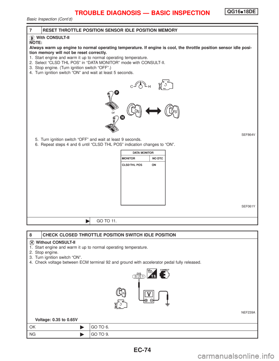
7 RESET THROTTLE POSITION SENSOR IDLE POSITION MEMORY
With CONSULT-II
NOTE:
Always warm up engine to normal operating temperature. If engine is cool, the throttle position sensor idle posi-
tion memory will not be reset correctly.
1. Start engine and warm it up to normal operating temperature.
2. Select ªCLSD THL POSº in ªDATA MONITORº mode with CONSULT-II.
3. Stop engine. (Turn ignition switch ªOFFº.)
4. Turn ignition switch ªONº and wait at least 5 seconds.
SEF864V
5. Turn ignition switch ªOFFº and wait at least 9 seconds.
6. Repeat steps 4 and 6 until ªCLSD THL POSº indication changes to ªONº.
SEF061Y
©GO TO 11.
8 CHECK CLOSED THROTTLE POSITION SWITCH IDLE POSITION
Without CONSULT-II
1. Start engine and warm it up to normal operating temperature.
2. Stop engine.
3. Turn ignition switch ªONº.
4. Check voltage between ECM terminal 92 and ground with accelerator pedal fully released.
NEF239A
Voltage: 0.35 to 0.65V
OK©GO TO 6.
NG©GO TO 9.
TROUBLE DIAGNOSIS Ð BASIC INSPECTIONQG16I18DE
Basic Inspection (Cont'd)
EC-74
Page 517 of 2267
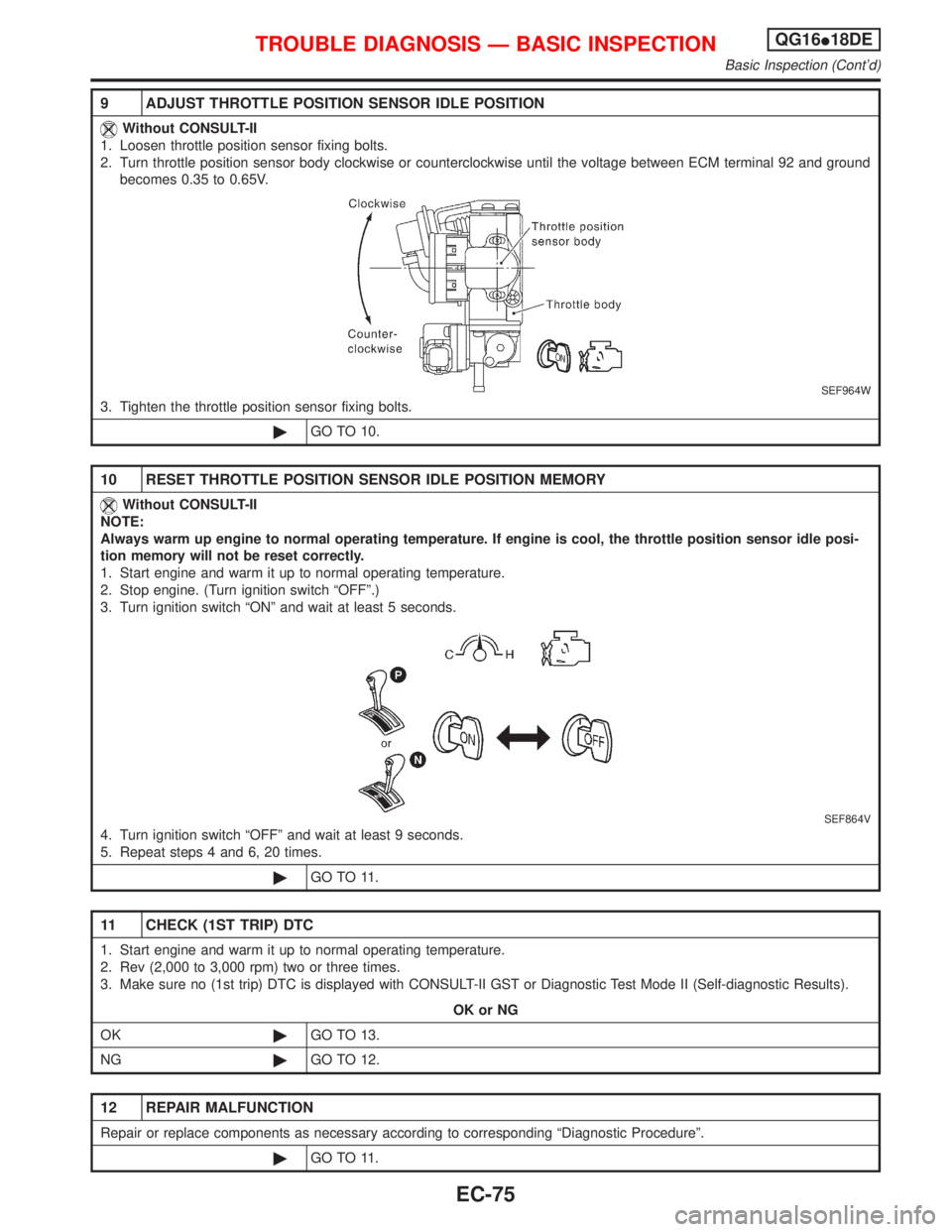
9 ADJUST THROTTLE POSITION SENSOR IDLE POSITION
Without CONSULT-II
1. Loosen throttle position sensor fixing bolts.
2. Turn throttle position sensor body clockwise or counterclockwise until the voltage between ECM terminal 92 and ground
becomes 0.35 to 0.65V.
SEF964W
3. Tighten the throttle position sensor fixing bolts.
©GO TO 10.
10 RESET THROTTLE POSITION SENSOR IDLE POSITION MEMORY
Without CONSULT-II
NOTE:
Always warm up engine to normal operating temperature. If engine is cool, the throttle position sensor idle posi-
tion memory will not be reset correctly.
1. Start engine and warm it up to normal operating temperature.
2. Stop engine. (Turn ignition switch ªOFFº.)
3. Turn ignition switch ªONº and wait at least 5 seconds.
SEF864V
4. Turn ignition switch ªOFFº and wait at least 9 seconds.
5. Repeat steps 4 and 6, 20 times.
©GO TO 11.
11 CHECK (1ST TRIP) DTC
1. Start engine and warm it up to normal operating temperature.
2. Rev (2,000 to 3,000 rpm) two or three times.
3. Make sure no (1st trip) DTC is displayed with CONSULT-II GST or Diagnostic Test Mode II (Self-diagnostic Results).
OK or NG
OK©GO TO 13.
NG©GO TO 12.
12 REPAIR MALFUNCTION
Repair or replace components as necessary according to corresponding ªDiagnostic Procedureº.
©GO TO 11.
TROUBLE DIAGNOSIS Ð BASIC INSPECTIONQG16I18DE
Basic Inspection (Cont'd)
EC-75
Page 528 of 2267
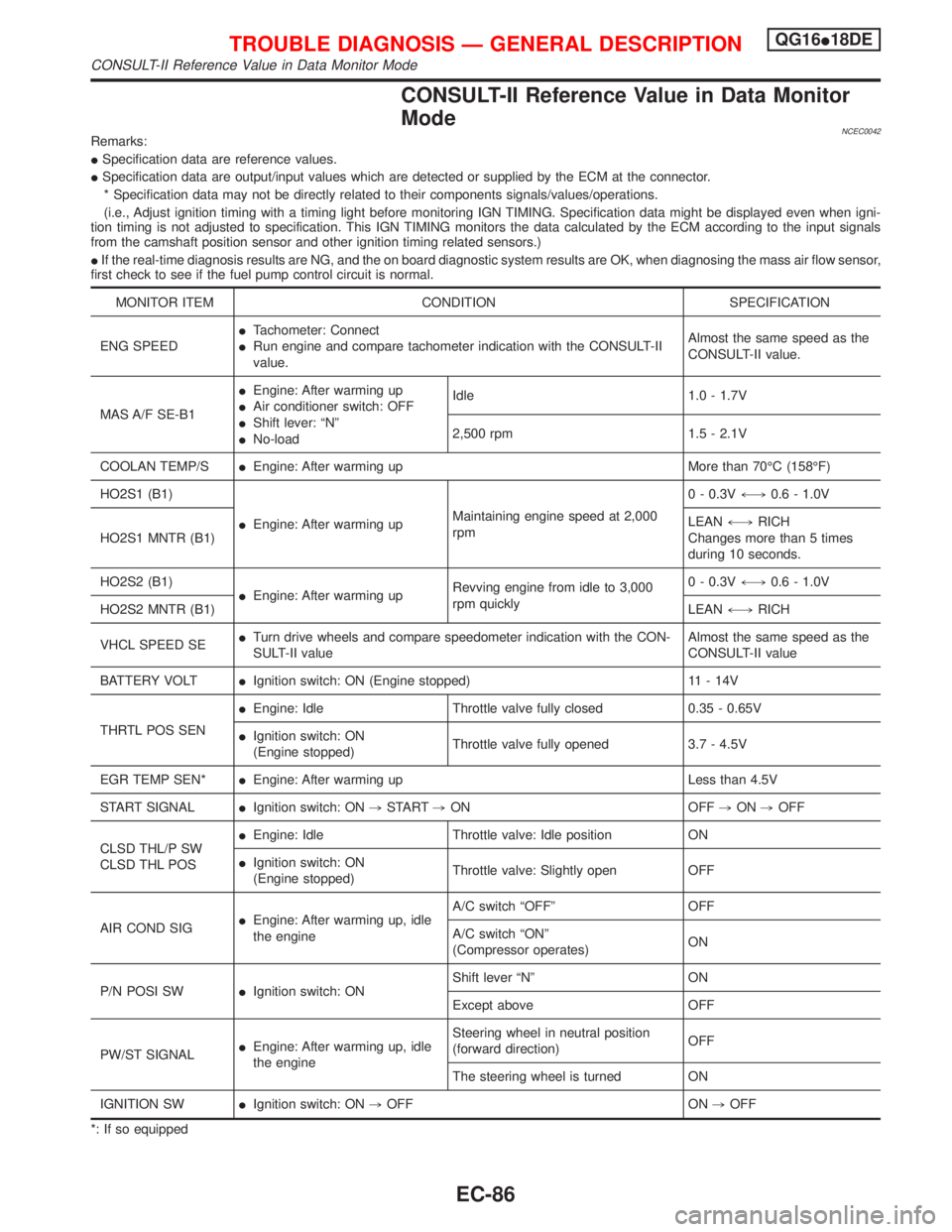
CONSULT-II Reference Value in Data Monitor
Mode
NCEC0042Remarks:
ISpecification data are reference values.
ISpecification data are output/input values which are detected or supplied by the ECM at the connector.
* Specification data may not be directly related to their components signals/values/operations.
(i.e., Adjust ignition timing with a timing light before monitoring IGN TIMING. Specification data might be displayed even when igni-
tion timing is not adjusted to specification. This IGN TIMING monitors the data calculated by the ECM according to the input signals
from the camshaft position sensor and other ignition timing related sensors.)
IIf the real-time diagnosis results are NG, and the on board diagnostic system results are OK, when diagnosing the mass air flow sensor,
first check to see if the fuel pump control circuit is normal.
MONITOR ITEM CONDITION SPECIFICATION
ENG SPEEDITachometer: Connect
IRun engine and compare tachometer indication with the CONSULT-II
value.Almost the same speed as the
CONSULT-II value.
MAS A/F SE-B1IEngine: After warming up
IAir conditioner switch: OFF
IShift lever: ªNº
INo-loadIdle 1.0 - 1.7V
2,500 rpm 1.5 - 2.1V
COOLAN TEMP/SIEngine: After warming up More than 70ÉC (158ÉF)
HO2S1 (B1)
IEngine: After warming upMaintaining engine speed at 2,000
rpm0 - 0.3V+,0.6 - 1.0V
HO2S1 MNTR (B1)LEAN+,RICH
Changes more than 5 times
during 10 seconds.
HO2S2 (B1)
IEngine: After warming upRevving engine from idle to 3,000
rpm quickly0 - 0.3V+,0.6 - 1.0V
HO2S2 MNTR (B1)LEAN+,RICH
VHCL SPEED SEITurn drive wheels and compare speedometer indication with the CON-
SULT-II valueAlmost the same speed as the
CONSULT-II value
BATTERY VOLTIIgnition switch: ON (Engine stopped) 11 - 14V
THRTL POS SENIEngine: Idle Throttle valve fully closed 0.35 - 0.65V
IIgnition switch: ON
(Engine stopped)Throttle valve fully opened 3.7 - 4.5V
EGR TEMP SEN*IEngine: After warming up Less than 4.5V
START SIGNALIIgnition switch: ON,START,ON OFF,ON,OFF
CLSD THL/P SW
CLSD THL POSIEngine: Idle Throttle valve: Idle position ON
IIgnition switch: ON
(Engine stopped)Throttle valve: Slightly open OFF
AIR COND SIGIEngine: After warming up, idle
the engineA/C switch ªOFFº OFF
A/C switch ªONº
(Compressor operates)ON
P/N POSI SWIIgnition switch: ONShift lever ªNº ON
Except above OFF
PW/ST SIGNALIEngine: After warming up, idle
the engineSteering wheel in neutral position
(forward direction)OFF
The steering wheel is turned ON
IGNITION SWIIgnition switch: ON,OFF ON,OFF
*: If so equipped
TROUBLE DIAGNOSIS Ð GENERAL DESCRIPTIONQG16I18DE
CONSULT-II Reference Value in Data Monitor Mode
EC-86
Page 557 of 2267
7 CHECK INPUT SIGNAL CIRCUIT
1. Check harness continuity between mass air flow sensor harness connector terminal 5 and ECM terminal 61.
Refer to wiring diagram.
Continuity should exist.
2. Also check harness for short to ground and short to power.
OK or NG
OK©GO TO 8.
NG©Repair open circuit or short to ground or short to power in harness or connectors.
8 CHECK MASS AIR FLOW SENSOR
Refer to ªComponent Inspectionº, EC-QG-115.
OK or NG
OK©GO TO 9.
NG©Replace mass air flow sensor.
9 CHECK INTERMITTENT INCIDENT
Perform ªTROUBLE DIAGNOSIS FOR INTERMITTENT INCIDENTº, EC-QG-102.
©INSPECTION END
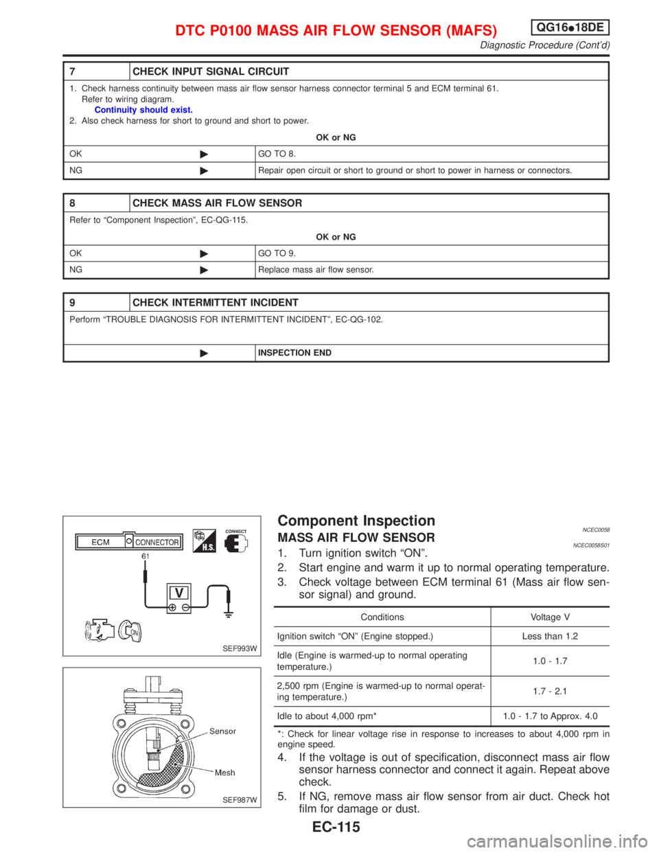
Component InspectionNCEC0058MASS AIR FLOW SENSORNCEC0058S011. Turn ignition switch ªONº.
2. Start engine and warm it up to normal operating temperature.
3. Check voltage between ECM terminal 61 (Mass air flow sen-
sor signal) and ground.
Conditions Voltage V
Ignition switch ªONº (Engine stopped.) Less than 1.2
Idle (Engine is warmed-up to normal operating
temperature.)1.0 - 1.7
2,500 rpm (Engine is warmed-up to normal operat-
ing temperature.)1.7 - 2.1
Idle to about 4,000 rpm* 1.0 - 1.7 to Approx. 4.0
*: Check for linear voltage rise in response to increases to about 4,000 rpm in
engine speed.
4. If the voltage is out of specification, disconnect mass air flow
sensor harness connector and connect it again. Repeat above
check.
5. If NG, remove mass air flow sensor from air duct. Check hot
film for damage or dust.
SEF993W
SEF987W
DTC P0100 MASS AIR FLOW SENSOR (MAFS)QG16I18DE
Diagnostic Procedure (Cont'd)
EC-115
Page 582 of 2267

On Board Diagnosis LogicNLEC0106To judge the malfunction, the output from the heated oxygen sen-
sor 1 (front) is monitored to determine whether the ªrichº output is
sufficiently high and whether the ªleanº output is sufficiently low.
When both the outputs are shifting to the lean side, the malfunc-
tion will be detected.
DTC No. Malfunction is detected when ... Check Items (Possible Cause)
P0131
0131IThe maximum and minimum voltages from the sensor
are not reached to the specified voltages.IHeated oxygen sensor 1 (front)
IHeated oxygen sensor 1 heater (front)
IFuel pressure
IInjectors
IIntake air leaks
DTC Confirmation ProcedureNLEC0107CAUTION:
Always drive vehicle at a safe speed.
NOTE:
If ªDTC Confirmation Procedureº has been previously conducted,
always turn ignition switch ªOFFº and wait at least 9 seconds
before conducting the next test.
TESTING CONDITION:
IAlways perform at a temperature above þ10ÉC (14ÉF).
IBefore performing the following procedure, confirm that
battery voltage is more than 11V at idle.
With CONSULT-II
1) Start engine and warm it up to normal operating temperature.
2) Stop engine and wait at least 9 seconds.
3) Turn ignition switch ªONº and select ªHO2S1 (B1) P0131º of
ªHO2S1º in ªDTC WORK SUPPORTº mode with CONSULT-II.
4) Touch ªSTARTº.
5) Start engine and let it idle for at least 3 minutes.
NOTE:
Never raise engine speed above 3,200 rpm after this step. If
the engine speed limit is exceeded, return to step 5.
6) When the following conditions are met, ªTESTINGº will be dis-
played on the CONSULT-II screen. Maintain the conditions
continuously until ªTESTINGº changes to ªCOMPLETEDº. (It
will take approximately 50 seconds or more.)
SEF300U
SEF827Y
SEF828Y
SEF651Y
DTC P0131 HEATED OXYGEN SENSOR 1 (FRONT)
(LEAN SHIFT MONITORING)QG16I18DE
On Board Diagnosis Logic
EC-140
Page 584 of 2267

2 CLEAR THE SELF-LEARNING DATA
With CONSULT-II
1. Start engine and warm it up to normal operating temperature.
2. Select ªSELF-LEARNING CONTº in ªWORK SUPPORTº mode with CONSULT-II.
3. Clear the self-learning control coefficient by touching ªSTARTº.
SEF652Y
4. Run engine for at least 10 minutes at idle speed.
Is the 1st trip DTC P0171 detected? Is it difficult to start engine?
Without CONSULT-II
1. Start engine and warm it up to normal operating temperature.
2. Turn ignition switch ªOFFº.
3. Disconnect mass air flow sensor harness connector, and restart and run engine for at least 3 seconds at idle speed.
SEF995W
4. Stop engine and reconnect mass air flow sensor harness connector.
5. Make sure diagnostic trouble code No. 0100 is displayed in Diagnostic Test Mode II.
6. Erase the diagnostic test mode II (Self-diagnostic results) memory. Refer to ªHow to Erase Emission-related Diagnostic
Informationº, EC-QG-44.
7. Make sure diagnostic trouble code No. 0000 is displayed in Diagnostic Test Mode II.
8. Run engine for at least 10 minutes at idle speed.
Is the 1st trip DTC 0171 detected? Is it difficult to start engine?
YesorNo
Ye s©Perform trouble diagnosis for DTC P0171. Refer to EC-QG-208.
No©GO TO 3.
3 CHECK FRONT HEATED OXYGEN SENSOR HEATER
Refer to ªComponent Inspectionº, EC-QG-170.
OK or NG
OK©GO TO 4.
NG©Replace front heated oxygen sensor.
DTC P0131 HEATED OXYGEN SENSOR 1 (FRONT)
(LEAN SHIFT MONITORING)QG16I18DE
Diagnostic Procedure (Cont'd)
EC-142
Page 588 of 2267

On Board Diagnosis LogicNLEC0114To judge the malfunction, the output from the heated oxygen sen-
sor 1 (front) is monitored to determine whether the ªrichº output is
sufficiently high. The ªleanº output is sufficiently low. When both the
outputs are shifting to the rich side, the malfunction will be
detected.
DTC No. Malfunction is detected when ... Check Items (Possible Cause)
P0132
0132IThe maximum and minimum voltages from the sensor
are beyond the specified voltages.IHeated oxygen sensor 1 (front)
IHeated oxygen sensor 1 heater (front)
IFuel pressure
IInjectors
DTC Confirmation ProcedureNLEC0115CAUTION:
Always drive vehicle at a safe speed.
NOTE:
If ªDTC Confirmation Procedureº has been previously conducted,
always turn ignition switch ªOFFº and wait at least 9 seconds
before conducting the next test.
TESTING CONDITION:
IAlways perform at a temperature above þ10ÉC (14ÉF).
IBefore performing the following procedure, confirm that
battery voltage is more than 11V at idle.
With CONSULT-II
1) Start engine and warm it up to normal operating temperature.
2) Stop engine and wait at least 9 seconds.
3) Turn ignition switch ªONº and select ªHO2S1 (B1) P0132º of
ªHO2S1º in ªDTC WORK SUPPORTº mode with CONSULT-II.
4) Touch ªSTARTº.
5) Start engine and let it idle for at least 3 minutes.
NOTE:
Never raise engine speed above 3,200 rpm after this step. If
the engine speed limit is exceeded, return to step 5.
6) When the following conditions are met, ªTESTINGº will be dis-
played on the CONSULT-II screen. Maintain the conditions
continuously until ªTESTINGº changes to ªCOMPLETEDº. (It
will take approximately 50 seconds or more.)
ENG SPEED 1,700 - 2,600 rpm
Vehicle speed 64 - 100 km/h (40 - 62 MPH)
B/FUEL SCHDL 3.0 - 5.2 msec
Selector lever Suitable position
SEF299UA
SEF829Y
SEF830Y
SEF655Y
DTC P0132 HEATED OXYGEN SENSOR 1 (FRONT)
(RICH SHIFT MONITORING)QG16I18DE
On Board Diagnosis Logic
EC-146
Page 590 of 2267

2 CLEAR THE SELF-LEARNING DATA
With CONSULT-II
1. Start engine and warm it up to normal operating temperature.
2. Select ªSELF-LEARNING CONTº in ªWORK SUPPORTº mode with CONSULT-II.
3. Clear the self-learning control coefficient by touching ªSTARTº.
SEF652Y
4. Run engine for at least 10 minutes at idle speed.
Is the 1st trip DTC P0172 detected? Is it difficult to start engine?
Without CONSULT-II
1. Start engine and warm it up to normal operating temperature.
2. Turn ignition switch ªOFFº.
3. Disconnect mass air flow sensor harness connector, and restart and run engine for at least 3 seconds at idle speed.
SEF995W
4. Stop engine and reconnect mass air flow sensor harness connector.
5. Make sure diagnostic trouble code No. 0100 is displayed in Diagnostic Test Mode II.
6. Erase the diagnostic test mode II (Self-diagnostic results) memory. Refer to ªHow to Erase Emission-related Diagnostic
Informationº, EC-QG-44.
7. Make sure diagnostic trouble code No. 0000 is displayed in Diagnostic Test Mode II.
8. Run engine for at least 10 minutes at idle speed.
Is the 1st trip DTC 0172 detected? Is it difficult to start engine?
YesorNo
Ye s©Perform trouble diagnosis for DTC P0172. Refer to EC-QG-215.
No©GO TO 3.
3 CHECK HARNESS CONNECTOR
1. Turn ignition switch ªOFFº.
2. Disconnect heated oxygen sensor 1 (front) harness connector.
3. Check harness connector for water.
Water should not exit.
OK or NG
OK©GO TO 4.
NG©Repair or replace harness connector.
DTC P0132 HEATED OXYGEN SENSOR 1 (FRONT)
(RICH SHIFT MONITORING)QG16I18DE
Diagnostic Procedure (Cont'd)
EC-148
Page 594 of 2267
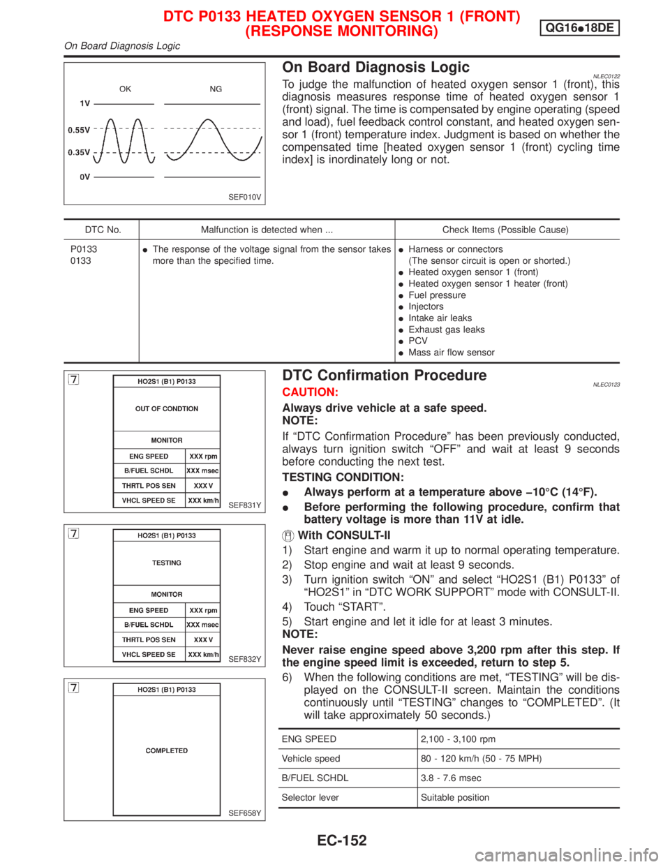
On Board Diagnosis LogicNLEC0122To judge the malfunction of heated oxygen sensor 1 (front), this
diagnosis measures response time of heated oxygen sensor 1
(front) signal. The time is compensated by engine operating (speed
and load), fuel feedback control constant, and heated oxygen sen-
sor 1 (front) temperature index. Judgment is based on whether the
compensated time [heated oxygen sensor 1 (front) cycling time
index] is inordinately long or not.
DTC No. Malfunction is detected when ... Check Items (Possible Cause)
P0133
0133IThe response of the voltage signal from the sensor takes
more than the specified time.IHarness or connectors
(The sensor circuit is open or shorted.)
IHeated oxygen sensor 1 (front)
IHeated oxygen sensor 1 heater (front)
IFuel pressure
IInjectors
IIntake air leaks
IExhaust gas leaks
IPCV
IMass air flow sensor
DTC Confirmation ProcedureNLEC0123CAUTION:
Always drive vehicle at a safe speed.
NOTE:
If ªDTC Confirmation Procedureº has been previously conducted,
always turn ignition switch ªOFFº and wait at least 9 seconds
before conducting the next test.
TESTING CONDITION:
IAlways perform at a temperature above þ10ÉC (14ÉF).
IBefore performing the following procedure, confirm that
battery voltage is more than 11V at idle.
With CONSULT-II
1) Start engine and warm it up to normal operating temperature.
2) Stop engine and wait at least 9 seconds.
3) Turn ignition switch ªONº and select ªHO2S1 (B1) P0133º of
ªHO2S1º in ªDTC WORK SUPPORTº mode with CONSULT-II.
4) Touch ªSTARTº.
5) Start engine and let it idle for at least 3 minutes.
NOTE:
Never raise engine speed above 3,200 rpm after this step. If
the engine speed limit is exceeded, return to step 5.
6) When the following conditions are met, ªTESTINGº will be dis-
played on the CONSULT-II screen. Maintain the conditions
continuously until ªTESTINGº changes to ªCOMPLETEDº. (It
will take approximately 50 seconds.)
ENG SPEED 2,100 - 3,100 rpm
Vehicle speed 80 - 120 km/h (50 - 75 MPH)
B/FUEL SCHDL 3.8 - 7.6 msec
Selector lever Suitable position
SEF010V
SEF831Y
SEF832Y
SEF658Y
DTC P0133 HEATED OXYGEN SENSOR 1 (FRONT)
(RESPONSE MONITORING)QG16I18DE
On Board Diagnosis Logic
EC-152
Page 598 of 2267
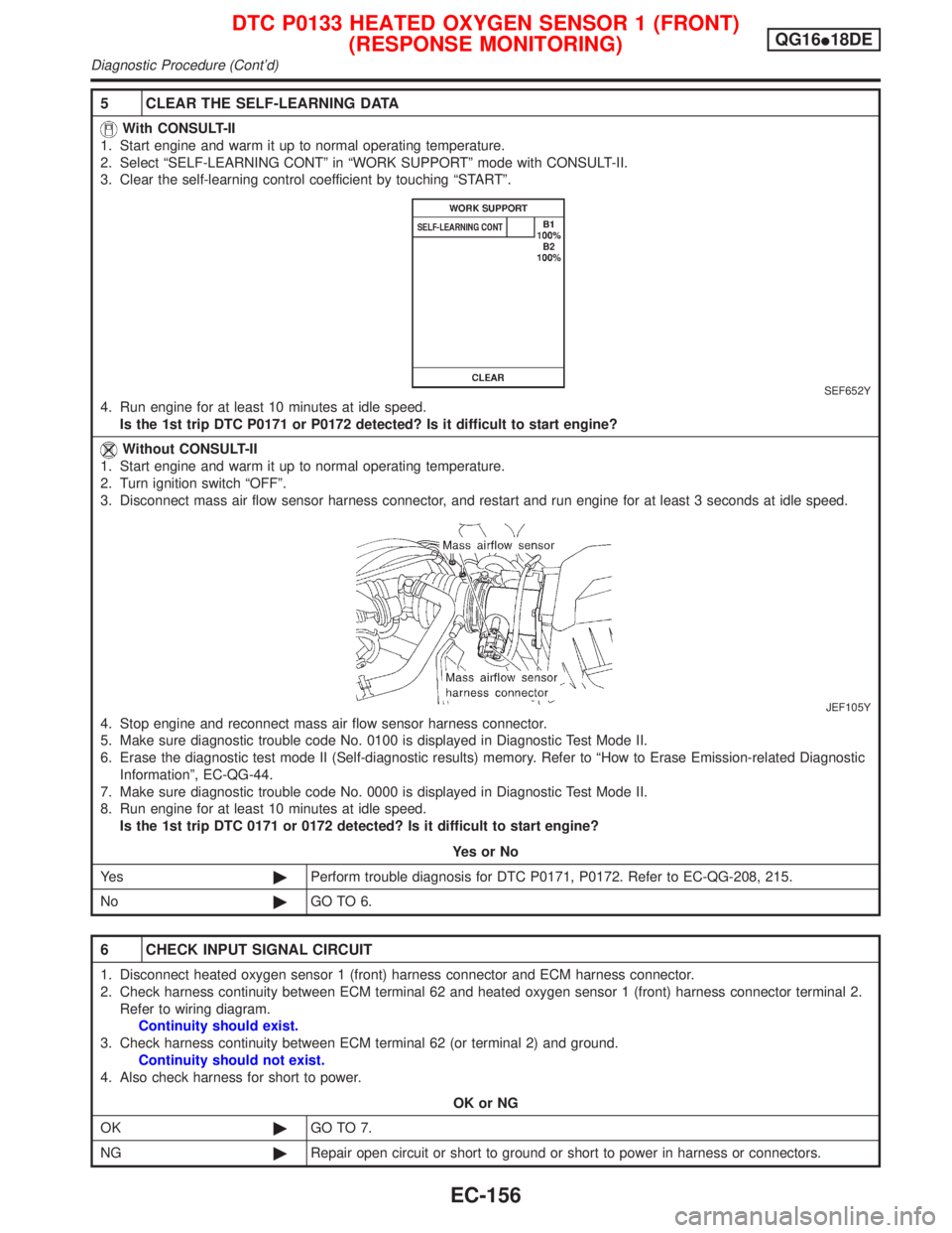
5 CLEAR THE SELF-LEARNING DATA
With CONSULT-II
1. Start engine and warm it up to normal operating temperature.
2. Select ªSELF-LEARNING CONTº in ªWORK SUPPORTº mode with CONSULT-II.
3. Clear the self-learning control coefficient by touching ªSTARTº.
SEF652Y
4. Run engine for at least 10 minutes at idle speed.
Is the 1st trip DTC P0171 or P0172 detected? Is it difficult to start engine?
Without CONSULT-II
1. Start engine and warm it up to normal operating temperature.
2. Turn ignition switch ªOFFº.
3. Disconnect mass air flow sensor harness connector, and restart and run engine for at least 3 seconds at idle speed.
JEF105Y
4. Stop engine and reconnect mass air flow sensor harness connector.
5. Make sure diagnostic trouble code No. 0100 is displayed in Diagnostic Test Mode II.
6. Erase the diagnostic test mode II (Self-diagnostic results) memory. Refer to ªHow to Erase Emission-related Diagnostic
Informationº, EC-QG-44.
7. Make sure diagnostic trouble code No. 0000 is displayed in Diagnostic Test Mode II.
8. Run engine for at least 10 minutes at idle speed.
Is the 1st trip DTC 0171 or 0172 detected? Is it difficult to start engine?
YesorNo
Ye s©Perform trouble diagnosis for DTC P0171, P0172. Refer to EC-QG-208, 215.
No©GO TO 6.
6 CHECK INPUT SIGNAL CIRCUIT
1. Disconnect heated oxygen sensor 1 (front) harness connector and ECM harness connector.
2. Check harness continuity between ECM terminal 62 and heated oxygen sensor 1 (front) harness connector terminal 2.
Refer to wiring diagram.
Continuity should exist.
3. Check harness continuity between ECM terminal 62 (or terminal 2) and ground.
Continuity should not exist.
4. Also check harness for short to power.
OK or NG
OK©GO TO 7.
NG©Repair open circuit or short to ground or short to power in harness or connectors.
DTC P0133 HEATED OXYGEN SENSOR 1 (FRONT)
(RESPONSE MONITORING)QG16I18DE
Diagnostic Procedure (Cont'd)
EC-156