stop start NISSAN PRIMERA 1999 Electronic Manual PDF
[x] Cancel search | Manufacturer: NISSAN, Model Year: 1999, Model line: PRIMERA, Model: NISSAN PRIMERA 1999Pages: 2267, PDF Size: 35.74 MB
Page 689 of 2267

2) Check engine coolant temperature in MODE 1 with GST.
Engine coolant temperature: Less than 40ÉC (104ÉF)
If the value is out of range, park the vehicle in a cool place and
allow the engine temperature to stabilize. Do not attempt to
lower the coolant temperature with a fan or means other than
ambient air. Doing so may produce an inaccurate diagnostic
result.
3) Start engine and let it idle monitoring the value of ªCOOLAN
TEMP/Sº. When the engine coolant temperature reaches 70ÉC
(158ÉF), immediately go to the next step.
4) Maintain the following conditions for at least 1 minute.
Engine speed Above 2,400 rpm
Vehicle speed Above 90 km/h (56 MPH)
Selector lever 4th or 5th
5) Stop vehicle.
6) Turn ignition switch ªOFFº and wait at least 9 seconds, then
turn ªONº.
7) Repeat step 2 to 4.
8) Select ªMODE 3º with GST.
9) If DTC is detected, go to ªDiagnostic Procedureº, EC-QG-249.
IWhen using GST, ªDTC CONFIRMATION PROCEDUREº
should be performed twice as much as when using CON-
SULT-II or ECM (Diagnostic Test Mode II) because GST
cannot display MODE 7 (1st trip DTC) concerning this
diagnosis. Therefore, using CONSULT-II or ECM (Diagnos-
tic Test Mode II) is recommended.
DTC P0400 EGR FUNCTION (CLOSE) (IF SO EQUIPPED)QG16I18DE
DTC Confirmation Procedure (Cont'd)
EC-247
Page 700 of 2267

On Board Diagnosis LogicNLEC0240The ECM monitors the switching frequency ratio of heated oxygen
sensors 1 (front) and 2 (rear).
A three way catalyst with high oxygen storage capacity will indicate
a low switching frequency of heated oxygen sensor 2 (rear). As
oxygen storage capacity decreases, the heated oxygen sensor 2
(rear) switching frequency will increase.
When the frequency ratio of heated oxygen sensors 1 (front) and
2 (rear) approaches a specified limit value, the three way catalyst
malfunction is diagnosed.
DTC No. Malfunction is detected when ... Check Items (Possible Cause)
P0420
0420IThree way catalyst does not operate properly.
IThree way catalyst does not have enough oxygen stor-
age capacity.IThree way catalyst
IExhaust tube
IIntake air leaks
IInjectors
IInjector leaks
ISpark plug
IImproper ignition timing
DTC Confirmation ProcedureNLEC0241CAUTION:
Always drive vehicle at a safe speed.
NOTE:
If ªDTC Confirmation Procedureº has been previously conducted,
always turn ignition switch ªOFFº and wait at least 9 seconds
before conducting the next test.
With CONSULT-II
TESTING CONDITION:
IOpen engine hood before conducting following proce-
dure.
IDo not hold engine speed more than specified minutes
below.
1) Turn ignition switch ªONº.
2) Select ªDTC & SRT CONFIRMATIONº then ªSRT WORK SUP-
PORTº mode with CONSULT-II.
3) Start engine.
4) Rev engine up to 3,000 500 rpm and hold it for 3 consecutive
minutes then release the accelerator pedal completely.
If ªCOMPLETEDº appears on the CONSULT-II screen, go to
step 7.
5) Wait 5 seconds at idle.
6) Rev engine up to 2,500 500 rpm and maintain it until ªINCMPº
of CATALYST changes to ªCMPLTº (it will take approximately
5 minutes.)
If not ªCMPLTº, stop engine and cool it down to less than 70ÉC
(158ÉF) and then retest from step 1.
7) Select ªSELF-DIAG RESULTSº mode with CONSULT-II.
8) Confirm that the 1st trip DTC is not detected.
If the 1st trip DTC is detected, go to ªDiagnostic Procedureº,
EC-259.
SEF184UD
SEF847Y
SEF848Y
SEF560X
DTC P0420 THREE WAY CATALYST FUNCTIONQG16I18DE
On Board Diagnosis Logic
EC-258
Page 701 of 2267
Overall Function CheckNCEC0242Use this procedure to check the overall function of the three way
catalyst. During this check, a 1st trip DTC might not be confirmed.
Without CONSULT-II
1) Start engine and drive vehicle at a speed of more than 70 km/h
(43 MPH) for 2 consecutive minutes.
2) Stop vehicle with engine running.
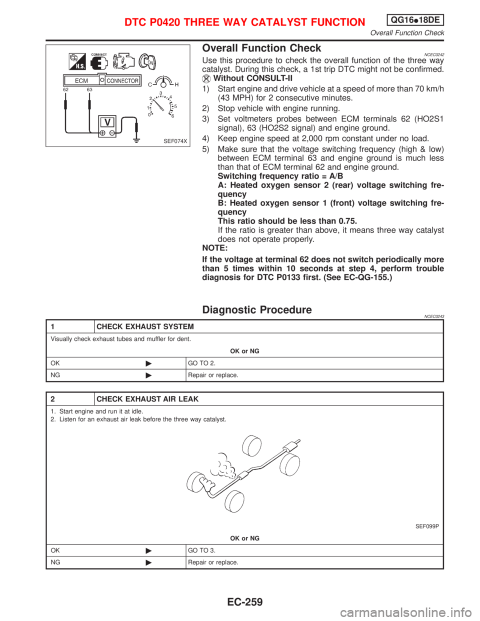
3) Set voltmeters probes between ECM terminals 62 (HO2S1
signal), 63 (HO2S2 signal) and engine ground.
4) Keep engine speed at 2,000 rpm constant under no load.
5) Make sure that the voltage switching frequency (high & low)
between ECM terminal 63 and engine ground is much less
than that of ECM terminal 62 and engine ground.
Switching frequency ratio = A/B
A: Heated oxygen sensor 2 (rear) voltage switching fre-
quency
B: Heated oxygen sensor 1 (front) voltage switching fre-
quency
This ratio should be less than 0.75.
If the ratio is greater than above, it means three way catalyst
does not operate properly.
NOTE:
If the voltage at terminal 62 does not switch periodically more
than 5 times within 10 seconds at step 4, perform trouble
diagnosis for DTC P0133 first. (See EC-QG-155.)
Diagnostic ProcedureNCEC0243
1 CHECK EXHAUST SYSTEM
Visually check exhaust tubes and muffler for dent.
OK or NG
OK©GO TO 2.
NG©Repair or replace.
2 CHECK EXHAUST AIR LEAK
1. Start engine and run it at idle.
2. Listen for an exhaust air leak before the three way catalyst.
SEF099P
OK or NG
OK©GO TO 3.
NG©Repair or replace.
SEF074X
DTC P0420 THREE WAY CATALYST FUNCTIONQG16I18DE
Overall Function Check
EC-259
Page 722 of 2267
9 REPLACE IACV-AAC VALVE
1. Replace IACV-AAC valve assembly.
2. Perform ªIdle Air Volume Learningº, EC-QG-33.
Is the result CMPLT or INCMP?
CMPLT or INCMP
CMPLT©INSPECTION END
INCMP©Follow the instruction of ªIdle Air Volume Learningº.
10 CHECK TARGET IDLE SPEED
1. Turn ignition switch ªOFFº.
2. Reconnect all harness connectors and vacuum hoses.
3. Start engine and warm it up to normal operating temperature.
4. Also warm up transmission to normal operating temperature.
IDrive vehicle for 10 minutes.
5. Stop vehicle with engine running.
6. Check target idle speed.
700 50 rpm
OK or NG
OK©GO TO 11.
NG©Perform ªIdle Air Volume Learningº, EC-QG-33.
11 CHECK INTERMITTENT INCIDENT
Perform ªTROUBLE DIAGNOSIS FOR INTERMITTENT INCIDENTº, EC-QG-102.
©INSPECTION END
DTC P0505 IDLE AIR CONTROL VALVE (IACV) Ð
AUXILIARY AIR CONTROL (AAC) VALVEQG16I18DE
Diagnostic Procedure (Cont'd)
EC-280
Page 750 of 2267
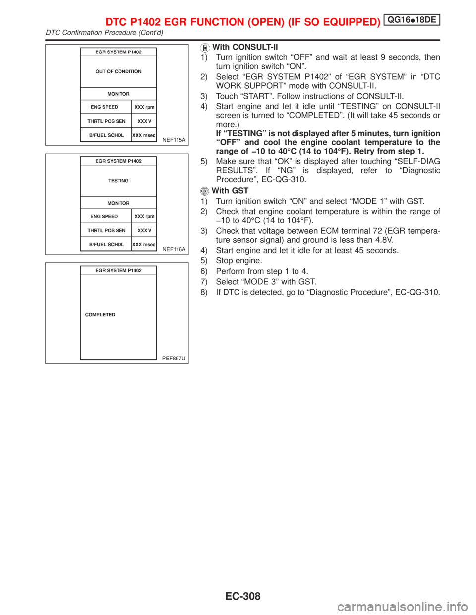
With CONSULT-II
1) Turn ignition switch ªOFFº and wait at least 9 seconds, then
turn ignition switch ªONº.
2) Select ªEGR SYSTEM P1402º of ªEGR SYSTEMº in ªDTC
WORK SUPPORTº mode with CONSULT-II.
3) Touch ªSTARTº. Follow instructions of CONSULT-II.
4) Start engine and let it idle until ªTESTINGº on CONSULT-II
screen is turned to ªCOMPLETEDº. (It will take 45 seconds or
more.)
If ªTESTINGº is not displayed after 5 minutes, turn ignition
ªOFFº and cool the engine coolant temperature to the
range of þ10 to 40ÉC (14 to 104ÉF). Retry from step 1.
5) Make sure that ªOKº is displayed after touching ªSELF-DIAG
RESULTSº. If ªNGº is displayed, refer to ªDiagnostic
Procedureº, EC-QG-310.
With GST
1) Turn ignition switch ªONº and select ªMODE 1º with GST.
2) Check that engine coolant temperature is within the range of
þ10 to 40ÉC (14 to 104ÉF).
3) Check that voltage between ECM terminal 72 (EGR tempera-
ture sensor signal) and ground is less than 4.8V.
4) Start engine and let it idle for at least 45 seconds.
5) Stop engine.
6) Perform from step 1 to 4.
7) Select ªMODE 3º with GST.
8) If DTC is detected, go to ªDiagnostic Procedureº, EC-QG-310.
NEF115A
NEF116A
PEF897U
DTC P1402 EGR FUNCTION (OPEN) (IF SO EQUIPPED)QG16I18DE
DTC Confirmation Procedure (Cont'd)
EC-308
Page 778 of 2267
System DescriptionNCEC0444
Sensor Input Signal to ECMECM func-
tionActuator
Camshaft position sensor (PHASE) Engine speed
Fuel pump
controlFuel pump relay
Ignition switch Start signal
The ECM activates the fuel pump for several seconds after the ignition switch is turned on to improve engine
startability. If the ECM receives a 180É signal from the camshaft position sensor, it knows that the engine is
rotating, and causes the pump to perform. If the 180É signal is not received when the ignition switch is on, the
engine stalls. The ECM stops pump operation and prevents battery discharging, thereby improving safety. The
ECM does not directly drive the fuel pump. It controls the ON/OFF fuel pump relay, which in turn controls the
fuel pump.
Condition Fuel pump operation
Ignition switch is turned to ON. Operates for 1 second
Engine running and cranking Operates
When engine is stopped (Signal is not sent from camshaft position sensor.) Stops in 1.5 seconds
Except as shown aboveStops
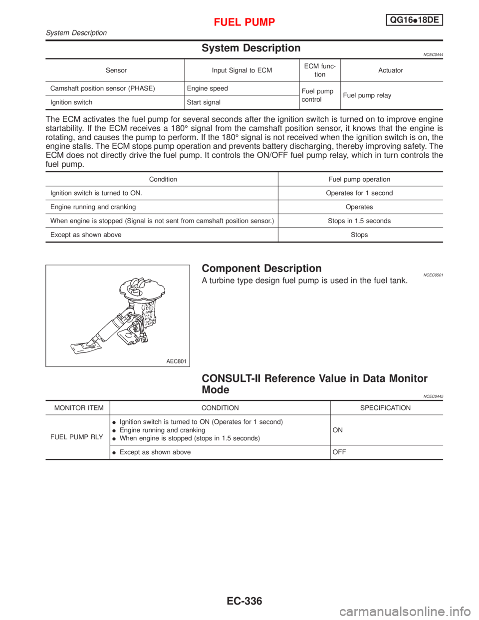
Component DescriptionNCEC0501A turbine type design fuel pump is used in the fuel tank.
CONSULT-II Reference Value in Data Monitor
Mode
NCEC0445
MONITOR ITEM CONDITION SPECIFICATION
FUEL PUMP RLYIIgnition switch is turned to ON (Operates for 1 second)
IEngine running and cranking
IWhen engine is stopped (stops in 1.5 seconds)ON
IExcept as shown above OFF
AEC801
FUEL PUMPQG16I18DE
System Description
EC-336
Page 791 of 2267
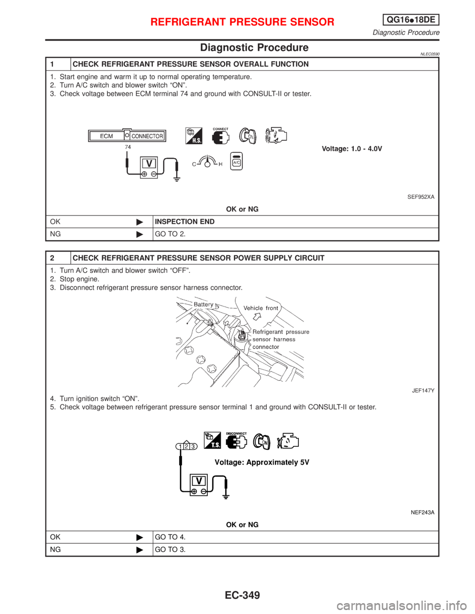
Diagnostic ProcedureNLEC0590
1 CHECK REFRIGERANT PRESSURE SENSOR OVERALL FUNCTION
1. Start engine and warm it up to normal operating temperature.
2. Turn A/C switch and blower switch ªONº.
3. Check voltage between ECM terminal 74 and ground with CONSULT-II or tester.
SEF952XA
OK or NG
OK©INSPECTION END
NG©GO TO 2.
2 CHECK REFRIGERANT PRESSURE SENSOR POWER SUPPLY CIRCUIT
1. Turn A/C switch and blower switch ªOFFº.
2. Stop engine.
3. Disconnect refrigerant pressure sensor harness connector.
JEF147Y
4. Turn ignition switch ªONº.
5. Check voltage between refrigerant pressure sensor terminal 1 and ground with CONSULT-II or tester.
NEF243A
OK or NG
OK©GO TO 4.
NG©GO TO 3.
REFRIGERANT PRESSURE SENSORQG16I18DE
Diagnostic Procedure
EC-349
Page 824 of 2267
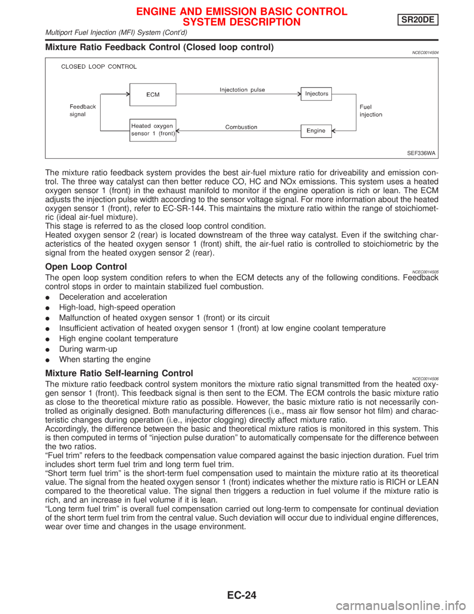
Mixture Ratio Feedback Control (Closed loop control)NCEC0014S04
The mixture ratio feedback system provides the best air-fuel mixture ratio for driveability and emission con-
trol. The three way catalyst can then better reduce CO, HC and NOx emissions. This system uses a heated
oxygen sensor 1 (front) in the exhaust manifold to monitor if the engine operation is rich or lean. The ECM
adjusts the injection pulse width according to the sensor voltage signal. For more information about the heated
oxygen sensor 1 (front), refer to EC-SR-144. This maintains the mixture ratio within the range of stoichiomet-
ric (ideal air-fuel mixture).
This stage is referred to as the closed loop control condition.
Heated oxygen sensor 2 (rear) is located downstream of the three way catalyst. Even if the switching char-
acteristics of the heated oxygen sensor 1 (front) shift, the air-fuel ratio is controlled to stoichiometric by the
signal from the heated oxygen sensor 2 (rear).
Open Loop ControlNCEC0014S05The open loop system condition refers to when the ECM detects any of the following conditions. Feedback
control stops in order to maintain stabilized fuel combustion.
IDeceleration and acceleration
IHigh-load, high-speed operation
IMalfunction of heated oxygen sensor 1 (front) or its circuit
IInsufficient activation of heated oxygen sensor 1 (front) at low engine coolant temperature
IHigh engine coolant temperature
IDuring warm-up
IWhen starting the engine
Mixture Ratio Self-learning ControlNCEC0014S06The mixture ratio feedback control system monitors the mixture ratio signal transmitted from the heated oxy-
gen sensor 1 (front). This feedback signal is then sent to the ECM. The ECM controls the basic mixture ratio
as close to the theoretical mixture ratio as possible. However, the basic mixture ratio is not necessarily con-
trolled as originally designed. Both manufacturing differences (i.e., mass air flow sensor hot film) and charac-
teristic changes during operation (i.e., injector clogging) directly affect mixture ratio.
Accordingly, the difference between the basic and theoretical mixture ratios is monitored in this system. This
is then computed in terms of ªinjection pulse durationº to automatically compensate for the difference between
the two ratios.
ªFuel trimº refers to the feedback compensation value compared against the basic injection duration. Fuel trim
includes short term fuel trim and long term fuel trim.
ªShort term fuel trimº is the short-term fuel compensation used to maintain the mixture ratio at its theoretical
value. The signal from the heated oxygen sensor 1 (front) indicates whether the mixture ratio is RICH or LEAN
compared to the theoretical value. The signal then triggers a reduction in fuel volume if the mixture ratio is
rich, and an increase in fuel volume if it is lean.
ªLong term fuel trimº is overall fuel compensation carried out long-term to compensate for continual deviation
of the short term fuel trim from the central value. Such deviation will occur due to individual engine differences,
wear over time and changes in the usage environment.
SEF336WA
ENGINE AND EMISSION BASIC CONTROL
SYSTEM DESCRIPTIONSR20DE
Multiport Fuel Injection (MFI) System (Cont'd)
EC-24
Page 832 of 2267
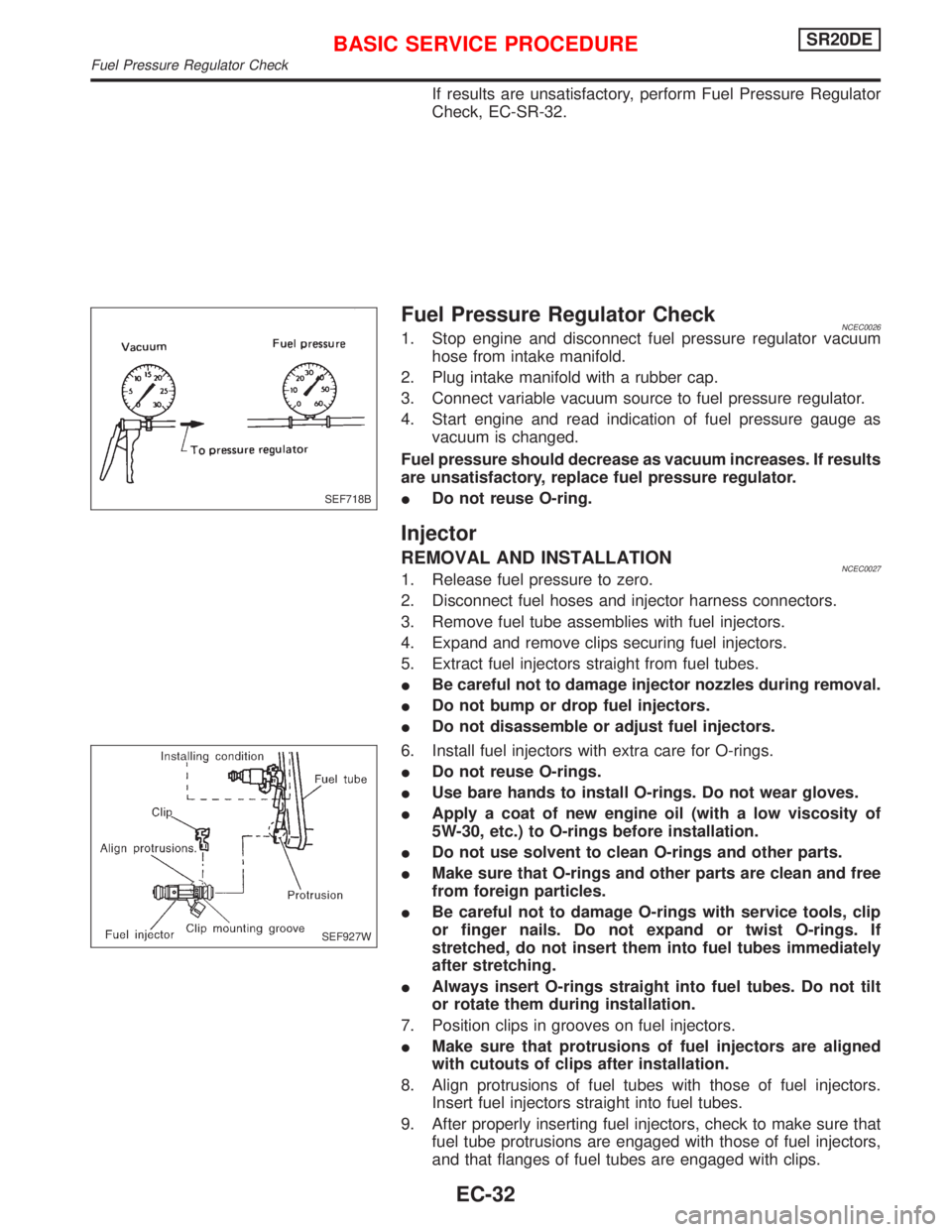
If results are unsatisfactory, perform Fuel Pressure Regulator
Check, EC-SR-32.
Fuel Pressure Regulator CheckNCEC00261. Stop engine and disconnect fuel pressure regulator vacuum
hose from intake manifold.
2. Plug intake manifold with a rubber cap.
3. Connect variable vacuum source to fuel pressure regulator.
4. Start engine and read indication of fuel pressure gauge as
vacuum is changed.
Fuel pressure should decrease as vacuum increases. If results
are unsatisfactory, replace fuel pressure regulator.
IDo not reuse O-ring.
Injector
REMOVAL AND INSTALLATIONNCEC00271. Release fuel pressure to zero.
2. Disconnect fuel hoses and injector harness connectors.
3. Remove fuel tube assemblies with fuel injectors.
4. Expand and remove clips securing fuel injectors.
5. Extract fuel injectors straight from fuel tubes.
IBe careful not to damage injector nozzles during removal.
IDo not bump or drop fuel injectors.
IDo not disassemble or adjust fuel injectors.
6. Install fuel injectors with extra care for O-rings.
IDo not reuse O-rings.
IUse bare hands to install O-rings. Do not wear gloves.
IApply a coat of new engine oil (with a low viscosity of
5W-30, etc.) to O-rings before installation.
IDo not use solvent to clean O-rings and other parts.
IMake sure that O-rings and other parts are clean and free
from foreign particles.
IBe careful not to damage O-rings with service tools, clip
or finger nails. Do not expand or twist O-rings. If
stretched, do not insert them into fuel tubes immediately
after stretching.
IAlways insert O-rings straight into fuel tubes. Do not tilt
or rotate them during installation.
7. Position clips in grooves on fuel injectors.
IMake sure that protrusions of fuel injectors are aligned
with cutouts of clips after installation.
8. Align protrusions of fuel tubes with those of fuel injectors.
Insert fuel injectors straight into fuel tubes.
9. After properly inserting fuel injectors, check to make sure that
fuel tube protrusions are engaged with those of fuel injectors,
and that flanges of fuel tubes are engaged with clips.
SEF718B
SEF927W
BASIC SERVICE PROCEDURESR20DE
Fuel Pressure Regulator Check
EC-32
Page 834 of 2267
Idle Speed/Ignition Timing/Idle Mixture Ratio
Adjustment
NCEC0028PREPARATIONNCEC0028S01IMake sure that the following parts are in good order.
a)Battery
b)Ignition system
c)Engine oil and coolant levels
d)Fuses
e)ECM harness connector
f)Vacuum hoses
g)Air intake system
(Oil filler cap, oil level gauge, etc.)
h)Fuel pressure
i)Engine compression
j)Throttle valve
k)EVAP system
IOn models equipped with air conditioner, checks should
be carried out while the air conditioner is ªOFFº.
IWhen checking idle speed on models equipped with CVT,
ignition timing and mixture ratio, checks should be carried
out while shift lever is in ªPº or ªNº position.
IWhen measuring ªCOº percentage, insert probe more
than 40 cm (15.7 in) into tail pipe.
ITurn off headlamps, heater blower, rear window defogger.
IOn vehicles equipped with daytime running light systems,
set lighting switch to the 1st position to light only small
lamps.
IKeep front wheels pointed straight ahead.
IIf engine stops immediately after starting or idle condition
is unstable, perform the following to initialize IACV-AAC
valve:
a)Stop engine and wait 9 seconds.
b)Turn ignition ªONº and wait 1 second.
c)Turn ignition ªOFFº and wait 9 seconds.
IMake the check after the cooling fan has stopped.
BASIC SERVICE PROCEDURESR20DE
Idle Speed/Ignition Timing/Idle Mixture Ratio Adjustment
EC-34