stop start NISSAN PRIMERA 1999 Electronic Manual PDF
[x] Cancel search | Manufacturer: NISSAN, Model Year: 1999, Model line: PRIMERA, Model: NISSAN PRIMERA 1999Pages: 2267, PDF Size: 35.74 MB
Page 844 of 2267
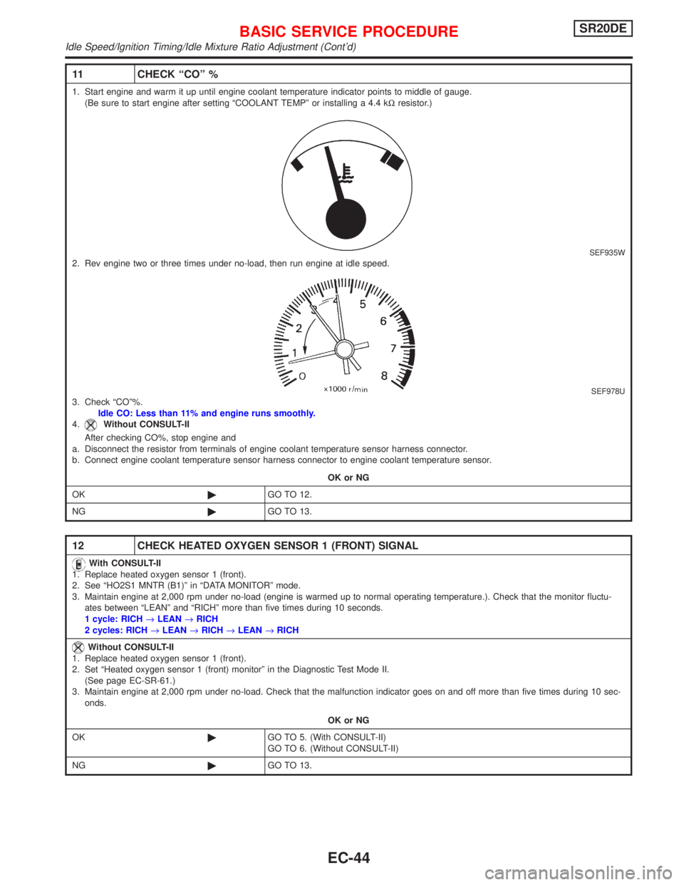
11 CHECK ªCOº %
1. Start engine and warm it up until engine coolant temperature indicator points to middle of gauge.
(Be sure to start engine after setting ªCOOLANT TEMPº or installing a 4.4 kWresistor.)
SEF935W2. Rev engine two or three times under no-load, then run engine at idle speed.
SEF978U3. Check ªCOº%.
Idle CO: Less than 11% and engine runs smoothly.
4.
Without CONSULT-II
After checking CO%, stop engine and
a. Disconnect the resistor from terminals of engine coolant temperature sensor harness connector.
b. Connect engine coolant temperature sensor harness connector to engine coolant temperature sensor.
OK or NG
OK©GO TO 12.
NG©GO TO 13.
12 CHECK HEATED OXYGEN SENSOR 1 (FRONT) SIGNAL
With CONSULT-II
1. Replace heated oxygen sensor 1 (front).
2. See ªHO2S1 MNTR (B1)º in ªDATA MONITORº mode.
3. Maintain engine at 2,000 rpm under no-load (engine is warmed up to normal operating temperature.). Check that the monitor fluctu-
ates between ªLEANº and ªRICHº more than five times during 10 seconds.
1 cycle: RICH®LEAN®RICH
2 cycles: RICH®LEAN®RICH®LEAN®RICH
Without CONSULT-II
1. Replace heated oxygen sensor 1 (front).
2. Set ªHeated oxygen sensor 1 (front) monitorº in the Diagnostic Test Mode II.
(See page EC-SR-61.)
3. Maintain engine at 2,000 rpm under no-load. Check that the malfunction indicator goes on and off more than five times during 10 sec-
onds.
OK or NG
OK©GO TO 5. (With CONSULT-II)
GO TO 6. (Without CONSULT-II)
NG©GO TO 13.
BASIC SERVICE PROCEDURESR20DE
Idle Speed/Ignition Timing/Idle Mixture Ratio Adjustment (Cont'd)
EC-44
Page 846 of 2267
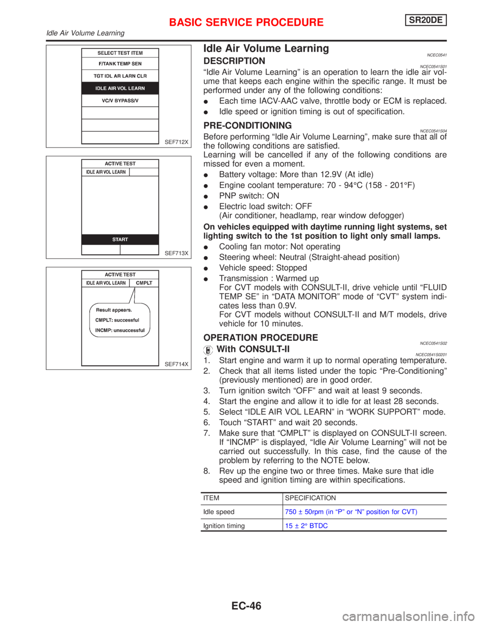
Idle Air Volume LearningNCEC0541DESCRIPTIONNCEC0541S01ªIdle Air Volume Learningº is an operation to learn the idle air vol-
ume that keeps each engine within the specific range. It must be
performed under any of the following conditions:
IEach time IACV-AAC valve, throttle body or ECM is replaced.
IIdle speed or ignition timing is out of specification.
PRE-CONDITIONINGNCEC0541S04Before performing ªIdle Air Volume Learningº, make sure that all of
the following conditions are satisfied.
Learning will be cancelled if any of the following conditions are
missed for even a moment.
IBattery voltage: More than 12.9V (At idle)
IEngine coolant temperature: 70 - 94ÉC (158 - 201ÉF)
IPNP switch: ON
IElectric load switch: OFF
(Air conditioner, headlamp, rear window defogger)
On vehicles equipped with daytime running light systems, set
lighting switch to the 1st position to light only small lamps.
ICooling fan motor: Not operating
ISteering wheel: Neutral (Straight-ahead position)
IVehicle speed: Stopped
ITransmission : Warmed up
For CVT models with CONSULT-II, drive vehicle until ªFLUID
TEMP SEº in ªDATA MONITORº mode of ªCVTº system indi-
cates less than 0.9V.
For CVT models without CONSULT-II and M/T models, drive
vehicle for 10 minutes.
OPERATION PROCEDURENCEC0541S02With CONSULT-IINCEC0541S02011. Start engine and warm it up to normal operating temperature.
2. Check that all items listed under the topic ªPre-Conditioningº
(previously mentioned) are in good order.
3. Turn ignition switch ªOFFº and wait at least 9 seconds.
4. Start the engine and allow it to idle for at least 28 seconds.
5. Select ªIDLE AIR VOL LEARNº in ªWORK SUPPORTº mode.
6. Touch ªSTARTº and wait 20 seconds.
7. Make sure that ªCMPLTº is displayed on CONSULT-II screen.
If ªINCMPº is displayed, ªIdle Air Volume Learningº will not be
carried out successfully. In this case, find the cause of the
problem by referring to the NOTE below.
8. Rev up the engine two or three times. Make sure that idle
speed and ignition timing are within specifications.
ITEM SPECIFICATION
Idle speed750 50rpm (in ªPº or ªNº position for CVT)
Ignition timing15 2É BTDC
SEF712X
SEF713X
SEF714X
BASIC SERVICE PROCEDURESR20DE
Idle Air Volume Learning
EC-46
Page 852 of 2267

Driving PatternNCEC0031S0303
NEF234A
SRT item
(CONSULT-II
screen term)
C ATA LY S T
HO2S
HO2S
HTRSelf-diagnostic
test item (CONSULT-II
screen term)
TW CATALYST
SYS
HO2S1
HO2S2
HO2S1
HTR
HO2S2
HTRPattern 1Pattern 2
*2
26 - 96 km/h
(53 - 60 MPH)
0 km/h
(0 MPH)
Keep idling
Engine
start [Engine coolant temperature is below 50ÉC (122ÉF).]Engine coolant temperature
becomes 70ÉC (158ÉF).Zone A Zone B(minutes)
Engine
stop *1 Driving patternNote: Always drive vehicle in safe manner according to traffic conditions and obey all traffic laws.
Refer to next page for more information and explanation of chart.
ON BOARD DIAGNOSTIC SYSTEM DESCRIPTIONSR20DE
Emission-related Diagnostic Information (Cont'd)
EC-52
Page 859 of 2267
DESCRIPTIONNCEC0032
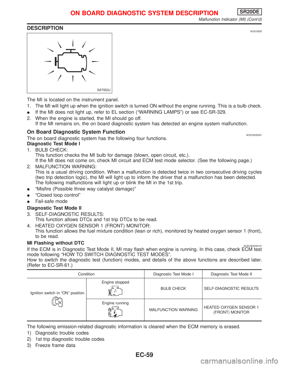
The MI is located on the instrument panel.
1. The MI will light up when the ignition switch is turned ON without the engine running. This is a bulb check.
IIf the MI does not light up, refer to EL section (ªWARNING LAMPSº) or see EC-SR-329.
2. When the engine is started, the MI should go off.
If the MI remains on, the on board diagnostic system has detected an engine system malfunction.
On Board Diagnostic System FunctionNCEC0032S01The on board diagnostic system has the following four functions.
Diagnostic Test Mode I
1. BULB CHECK:
This function checks the MI bulb for damage (blown, open circuit, etc.).
If the MI does not come on, check MI circuit and ECM test mode selector. (See the following page.)
2. MALFUNCTION WARNING:
This is a usual driving condition. When a malfunction is detected twice in two consecutive driving cycles
(two trip detection logic), the MI will light up to inform the driver that a malfunction has been detected.
The following malfunctions will light up or blink the MI in the 1st trip.
IªMisfire (Possible three way catalyst damage)º
IªClosed loop controlº
IFail-safe mode
Diagnostic Test Mode II
3. SELF-DIAGNOSTIC RESULTS:
This function allows DTCs and 1st trip DTCs to be read.
4. HEATED OXYGEN SENSOR 1 (FRONT) MONITOR:
This function allows the fuel mixture condition (lean or rich), monitored by heated oxygen sensor 1 (front),
to be read.
MI Flashing without DTC
NCEC0032S0101If the ECM is in Diagnostic Test Mode II, MI may flash when engine is running. In this case, check ECM test
mode following ªHOW TO SWITCH DIAGNOSTIC TEST MODESº.
How to switch the diagnostic test (function) modes, and details of the above functions are described later.
(Refer to EC-SR-61.)
Condition Diagnostic Test Mode I Diagnostic Test Mode II
Ignition switch in ªONº position
Engine stopped
BULB CHECK SELF-DIAGNOSTIC RESULTS
Engine running
MALFUNCTION WARNINGHEATED OXYGEN SENSOR 1
(FRONT) MONITOR
The following emission-related diagnostic information is cleared when the ECM memory is erased.
1) Diagnostic trouble codes
2) 1st trip diagnostic trouble codes
3) Freeze frame data
SAT652J
ON BOARD DIAGNOSTIC SYSTEM DESCRIPTIONSR20DE
Malfunction Indicator (MI) (Cont'd)
EC-59
Page 871 of 2267

WORK SUPPORT MODENCEC0034S04
WORK ITEM CONDITION USAGE
IGNITION TIMING ADJIIGNITION TIMING FEEDBACK CONTROL WILL BE
HELD BY TOUCHING ªSTARTº. AFTER DOING SO,
ADJUST IGNITION TIMING WITH A TIMING LIGHT BY
TURNING THE CAMSHAFT POSITION SENSOR.When adjusting initial ignition tim-
ing
FUEL PRESSURE RELEASEIFUEL PUMP WILL STOP BY TOUCHING ªSTARTº
DURING IDLING.
CRANK A FEW TIMES AFTER ENGINE STALLS.When releasing fuel pressure
from fuel line
TARGET IDLE RPM ADJIIDLE CONDITION When setting target idle speed
TARGET IGNITION TIMING ADJIIDLE CONDITION When adjusting target ignition
timing
After adjustment, confirm target
ignition timing with a timing light.
SELF DIAGNOSTIC MODENCEC0034S05DTC and 1st Trip DTCNCEC0034S0501Regarding items of ªDTC and 1st trip DTCº, refer to
ªTROUBLE DIAGNOSIS Ð INDEXº, EC-SR-6.
Freeze Frame Data and 1st Trip Freeze Frame DataNCEC0034S0502
Freeze frame data
item*Description
DIAG TROUBLE
CODE
[PXXXX]IEngine Control component part/control system has a trouble code, it is displayed as ªPXXXXº. [Refer
to ªAlphabetical & P No. Index for DTCº (EC-SR-6).]
FUEL SYS DATAIªFuel injection system statusº at the moment a malfunction is detected is displayed.
IOne mode in the following is displayed.
ªMODE 2º: Open loop due to detected system malfunction
ªMODE 3º: Open loop due to driving conditions (power enrichment, deceleration enrichment)
ªMODE 4º: Closed loop - using oxygen sensor(s) as feedback for fuel control
ªMODE 5º: Open loop - has not yet satisfied condition to go to closed loop
CAL/LD VALUE [%]IThe calculated load value at the moment a malfunction is detected is displayed.
COOLANT TEMP [ÉC]
or [ÉF]IThe engine coolant temperature at the moment a malfunction is detected is displayed.
S-FUEL TRIM [%]IªShort-term fuel trimº at the moment a malfunction is detected is displayed.
IThe short-term fuel trim indicates dynamic or instantaneous feedback compensation to the base fuel
schedule.
L-FUEL TRIM [%]IªLong-term fuel trimº at the moment a malfunction is detected is displayed.
IThe long-term fuel trim indicates much more gradual feedback compensation to the base fuel schedule
than short-term fuel trim.
ENGINE SPEED [rpm]IThe engine speed at the moment a malfunction is detected is displayed.
VHCL SPEED [km/h]
or [mph]IThe vehicle speed at the moment a malfunction is detected is displayed.
*: The items are the same as those of 1st trip freeze frame data.
ON BOARD DIAGNOSTIC SYSTEM DESCRIPTIONSR20DE
CONSULT-II (Cont'd)
EC-71
Page 872 of 2267

DATA MONITOR MODENCEC0034S06
Monitored item [Unit]ECM
input
signalsMain
signalsDescription Remarks
ENG SPEED [rpm]qqIIndicates the engine speed computed
from the REF signal (180É signal) of the
camshaft position sensor.IAccuracy becomes poor if engine
speed drops below the idle rpm.
IIf the signal is interrupted while the
engine is running, an abnormal value
may be indicated.
MAS A/F SE-B1 [V]qqIThe signal voltage of the mass air flow
sensor is displayed.IWhen the engine is stopped, a cer-
tain value is indicated.
COOLAN TEMP/S
[ÉC] or [ÉF]qqIThe engine coolant temperature (deter-
mined by the signal voltage of the
engine coolant temperature sensor) is
displayed.IWhen the engine coolant tempera-
ture sensor is open or short-circuited,
ECM enters fail-safe mode. The
engine coolant temperature deter-
mined by the ECM is displayed.
HO2S1 (B1) [V]qqIThe signal voltage of the heated oxygen
sensor 1 (front) is displayed.
HO2S2 (B1) [V]qIThe signal voltage of the heated oxygen
sensor 2 (rear) is displayed.
HO2S1 MNTR (B1)
[RICH/LEAN]qIDisplay of heated oxygen sensor 1
(front) signal during air-fuel ratio feed-
back control:
RICH ... means the mixture became
ªrichº, and control is being affected
toward a leaner mixture.
LEAN ... means the mixture became
ªleanº, and control is being affected
toward a rich mixture.IAfter turning ON the ignition switch,
ªRICHº is displayed until air-fuel mix-
ture ratio feedback control begins.
IWhen the air-fuel ratio feedback is
clamped, the value just before the
clamping is displayed continuously.
HO2S2 MNTR (B1)
[RICH/LEAN]qIDisplay of heated oxygen sensor 2 (rear)
signal:
RICH ... means the amount of oxygen
after three way catalyst is relatively
small.
LEAN ... means the amount of oxygen
after three way catalyst is relatively
large.IWhen the engine is stopped, a cer-
tain value is indicated.
VHCL SPEED SE
[km/h] or [mph]qqIThe vehicle speed computed from the
vehicle speed sensor signal or ABS
actuator and electric unit (control unit)
signal is displayed.
BATTERY VOLT [V]qIThe power supply voltage of ECM is dis-
played.
THRTL POS SEN [V]qqIThe throttle position sensor signal volt-
age is displayed.
INT/A TEMP SE
[ÉC] or [ÉF]qIThe intake air temperature determined
by the signal voltage of the intake air
temperature sensor is indicated.
START SIGNAL
[ON/OFF]qqIIndicates [ON/OFF] condition from the
starter signal.IAfter starting the engine, [OFF] is
displayed regardless of the starter
signal.
CLSD THL/P SW
[ON/OFF]IIndicates mechanical contact [ON/OFF]
condition of the closed throttle position
switch.
CLSD THL POS
[ON/OFF]qqIIndicates idle position [ON/OFF] com-
puted by ECM according to the throttle
position sensor signal.
ON BOARD DIAGNOSTIC SYSTEM DESCRIPTIONSR20DE
CONSULT-II (Cont'd)
EC-72
Page 884 of 2267
Basic InspectionNCEC0038Precaution:
Perform Basic Inspection without electrical or mechanical loads applied;
IHeadlamp switch is OFF,
IOn vehicles equipped with daytime running light systems, set lighting switch to the 1st position to light only
small lamps.
IAir conditioner switch is OFF,
IRear window defogger switch is OFF,
ISteering wheel is in the straight-ahead position, etc.
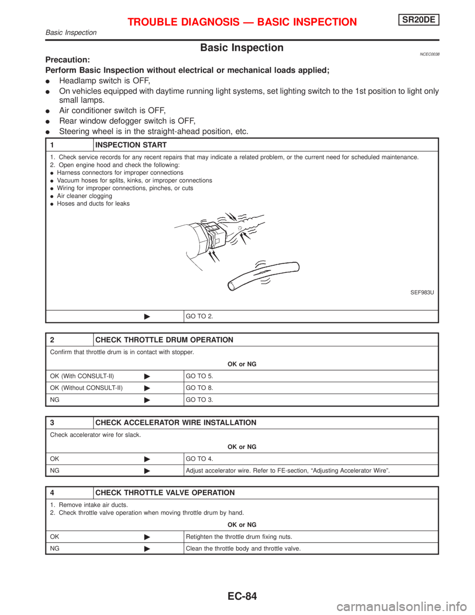
1 INSPECTION START
1. Check service records for any recent repairs that may indicate a related problem, or the current need for scheduled maintenance.
2. Open engine hood and check the following:
IHarness connectors for improper connections
IVacuum hoses for splits, kinks, or improper connections
IWiring for improper connections, pinches, or cuts
IAir cleaner clogging
IHoses and ducts for leaks
SEF983U
©GO TO 2.
2 CHECK THROTTLE DRUM OPERATION
Confirm that throttle drum is in contact with stopper.
OK or NG
OK (With CONSULT-II)©GO TO 5.
OK (Without CONSULT-II)©GO TO 8.
NG©GO TO 3.
3 CHECK ACCELERATOR WIRE INSTALLATION
Check accelerator wire for slack.
OK or NG
OK©GO TO 4.
NG©Adjust accelerator wire. Refer to FE-section, ªAdjusting Accelerator Wireº.
4 CHECK THROTTLE VALVE OPERATION
1. Remove intake air ducts.
2. Check throttle valve operation when moving throttle drum by hand.
OK or NG
OK©Retighten the throttle drum fixing nuts.
NG©Clean the throttle body and throttle valve.
TROUBLE DIAGNOSIS Ð BASIC INSPECTIONSR20DE
Basic Inspection
EC-84
Page 885 of 2267
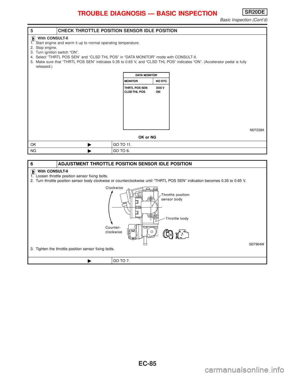
5 CHECK THROTTLE POSITION SENSOR IDLE POSITION
With CONSULT-II
1. Start engine and warm it up to normal operating temperature.
2. Stop engine.
3. Turn ignition switch ªONº.
4. Select ºTHRTL POS SENº and ªCLSD THL POSº in ªDATA MONITORº mode with CONSULT-II.
5. Make sure that ªTHRTL POS SENº indicates 0.35 to 0.65 V, and ªCLSD THL POSº indicates ªONº. (Accelerator pedal is fully
released.)
NEF238A
OK or NG
OK©GO TO 11.
NG©GO TO 6.
6 ADJUSTMENT THROTTLE POSITION SENSOR IDLE POSITION
With CONSULT-II
1. Loosen throttle position sensor fixing bolts.
2. Turn throttle position sensor body clockwise or counterclockwise until ªTHRTL POS SENº indication becomes 0.35 to 0.65 V.
SEF964W3. Tighten the throttle position sensor fixing bolts.
©GO TO 7.
TROUBLE DIAGNOSIS Ð BASIC INSPECTIONSR20DE
Basic Inspection (Cont'd)
EC-85
Page 886 of 2267
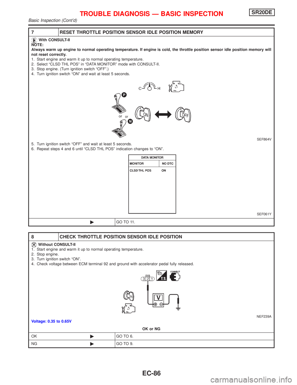
7 RESET THROTTLE POSITION SENSOR IDLE POSITION MEMORY
With CONSULT-II
NOTE:
Always warm up engine to normal operating temperature. If engine is cold, the throttle position sensor idle position memory will
not reset correctly.
1. Start engine and warm it up to normal operating temperature.
2. Select ªCLSD THL POSº in ªDATA MONITORº mode with CONSULT-II.
3. Stop engine. (Turn ignition switch ªOFFº.)
4. Turn ignition switch ªONº and wait at least 5 seconds.
SEF864V5. Turn ignition switch ªOFFº and wait at least 5 seconds.
6. Repeat steps 4 and 6 until ªCLSD THL POSº indication changes to ªONº.
SEF061Y
©GO TO 11.
8 CHECK THROTTLE POSITION SENSOR IDLE POSITION
Without CONSULT-II
1. Start engine and warm it up to normal operating temperature.
2. Stop engine.
3. Turn ignition switch ªONº.
4. Check voltage between ECM terminal 92 and ground with accelerator pedal fully released.
NEF239AVoltage: 0.35 to 0.65V
OK or NG
OK©GO TO 6.
NG©GO TO 9.
or
TROUBLE DIAGNOSIS Ð BASIC INSPECTIONSR20DE
Basic Inspection (Cont'd)
EC-86
Page 887 of 2267
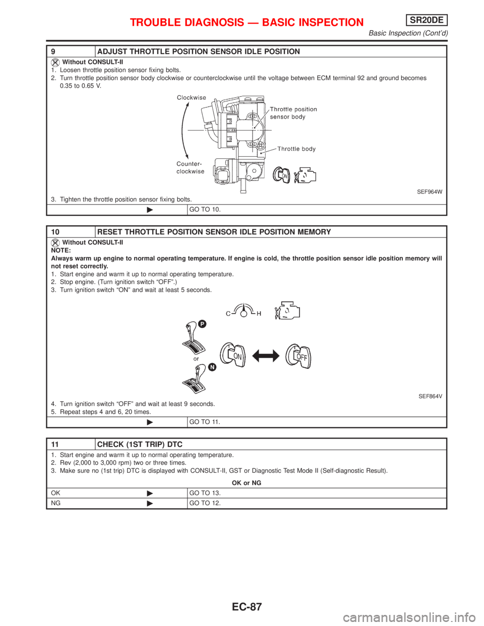
9 ADJUST THROTTLE POSITION SENSOR IDLE POSITION
Without CONSULT-II
1. Loosen throttle position sensor fixing bolts.
2. Turn throttle position sensor body clockwise or counterclockwise until the voltage between ECM terminal 92 and ground becomes
0.35 to 0.65 V.
SEF964W3. Tighten the throttle position sensor fixing bolts.
©GO TO 10.
10 RESET THROTTLE POSITION SENSOR IDLE POSITION MEMORY
Without CONSULT-II
NOTE:
Always warm up engine to normal operating temperature. If engine is cold, the throttle position sensor idle position memory will
not reset correctly.
1. Start engine and warm it up to normal operating temperature.
2. Stop engine. (Turn ignition switch ªOFFº.)
3. Turn ignition switch ªONº and wait at least 5 seconds.
SEF864V4. Turn ignition switch ªOFFº and wait at least 9 seconds.
5. Repeat steps 4 and 6, 20 times.
©GO TO 11.
11 CHECK (1ST TRIP) DTC
1. Start engine and warm it up to normal operating temperature.
2. Rev (2,000 to 3,000 rpm) two or three times.
3. Make sure no (1st trip) DTC is displayed with CONSULT-II, GST or Diagnostic Test Mode II (Self-diagnostic Result).
OK or NG
OK©GO TO 13.
NG©GO TO 12.
TROUBLE DIAGNOSIS Ð BASIC INSPECTIONSR20DE
Basic Inspection (Cont'd)
EC-87