NISSAN PRIMERA 1999 Electronic Repair Manual
Manufacturer: NISSAN, Model Year: 1999, Model line: PRIMERA, Model: NISSAN PRIMERA 1999Pages: 2267, PDF Size: 35.74 MB
Page 401 of 2267
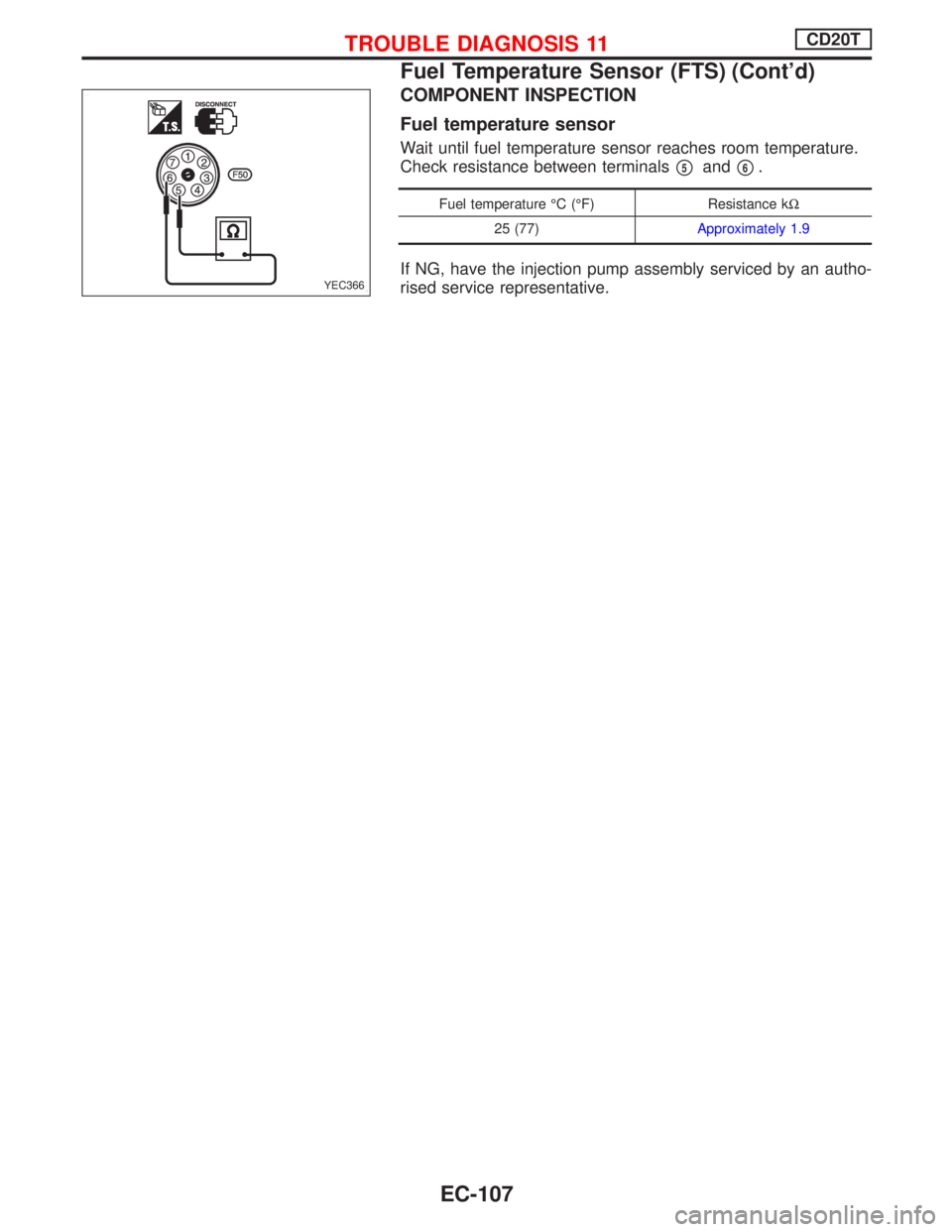
COMPONENT INSPECTION
Fuel temperature sensor
Wait until fuel temperature sensor reaches room temperature.
Check resistance between terminals
p5andp6.
Fuel temperature ÉC (ÉF) Resistance kW
25 (77)Approximately 1.9
If NG, have the injection pump assembly serviced by an autho-
rised service representative.YEC366
TROUBLE DIAGNOSIS 11CD20T
Fuel Temperature Sensor (FTS) (Cont'd)
EC-107
Page 402 of 2267
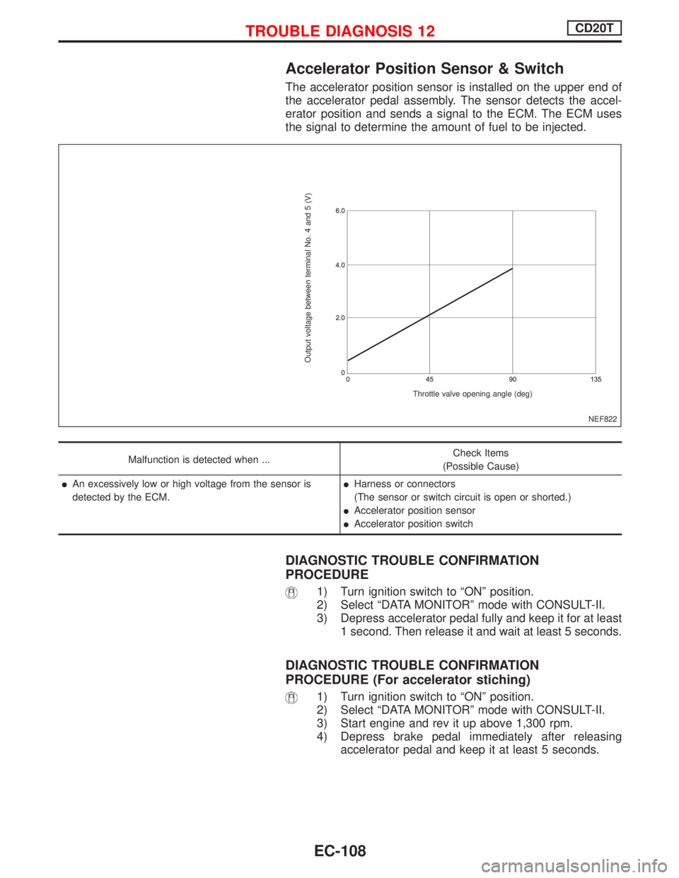
Accelerator Position Sensor & Switch
The accelerator position sensor is installed on the upper end of
the accelerator pedal assembly. The sensor detects the accel-
erator position and sends a signal to the ECM. The ECM uses
the signal to determine the amount of fuel to be injected.
Malfunction is detected when ...Check Items
(Possible Cause)
lAn excessively low or high voltage from the sensor is
detected by the ECM.lHarness or connectors
(The sensor or switch circuit is open or shorted.)
lAccelerator position sensor
lAccelerator position switch
DIAGNOSTIC TROUBLE CONFIRMATION
PROCEDURE
1) Turn ignition switch to ªONº position.
2) Select ªDATA MONITORº mode with CONSULT-II.
3) Depress accelerator pedal fully and keep it for at least
1 second. Then release it and wait at least 5 seconds.
DIAGNOSTIC TROUBLE CONFIRMATION
PROCEDURE (For accelerator stiching)
1) Turn ignition switch to ªONº position.
2) Select ªDATA MONITORº mode with CONSULT-II.
3) Start engine and rev it up above 1,300 rpm.
4) Depress brake pedal immediately after releasing
accelerator pedal and keep it at least 5 seconds.
NEF822
Output voltage between terminal No. 4 and 5 (V)
Throttle valve opening angle (deg)
TROUBLE DIAGNOSIS 12CD20T
EC-108
Page 403 of 2267
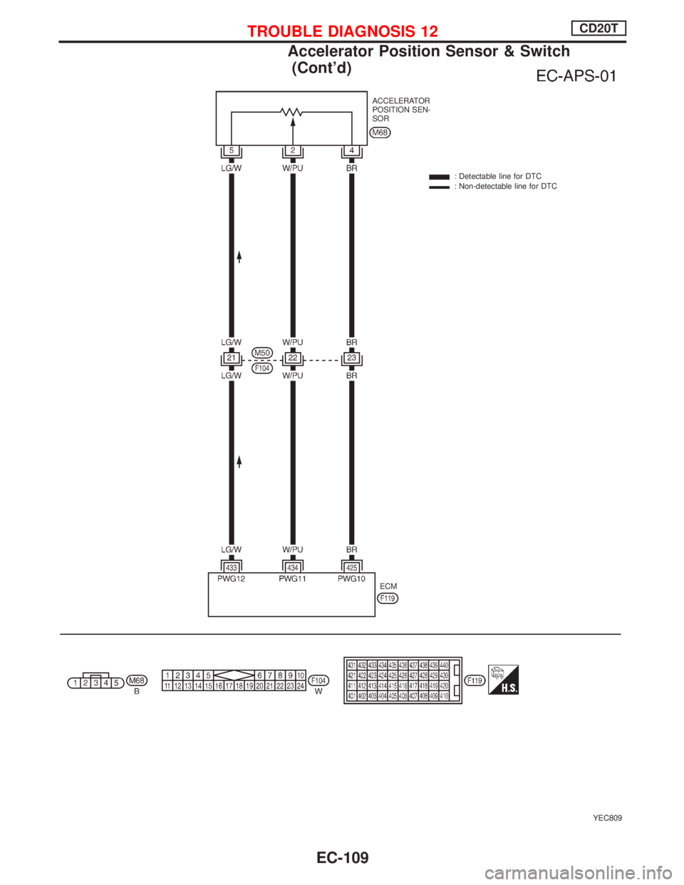
YEC809
ACCELERATOR
POSITION SEN-
SOR
: Detectable line for DTC
: Non-detectable line for DTC
ECM
TROUBLE DIAGNOSIS 12CD20T
Accelerator Position Sensor & Switch
(Cont'd)
EC-109
Page 404 of 2267
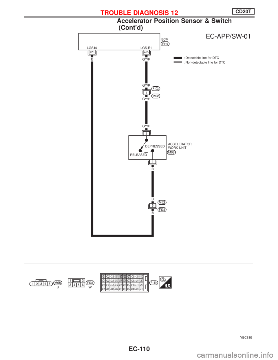
YEC810 : Detectable line for DTC
: Non-detectable line for DTC
ACCELERATOR
WORK UNIT ECM
RELEASEDDEPRESSED
TROUBLE DIAGNOSIS 12CD20T
Accelerator Position Sensor & Switch
(Cont'd)
EC-110
Page 405 of 2267
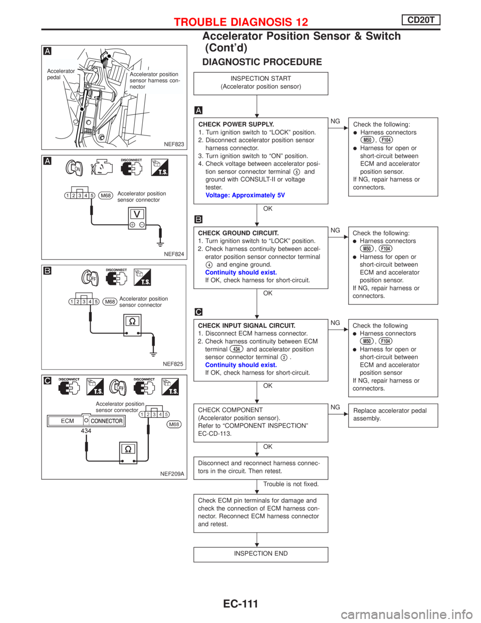
DIAGNOSTIC PROCEDURE
INSPECTION START
(Accelerator position sensor)
CHECK POWER SUPPLY.
1. Turn ignition switch to ªLOCKº position.
2. Disconnect accelerator position sensor
harness connector.
3. Turn ignition switch to ªONº position.
4. Check voltage between accelerator posi-
tion sensor connector terminal
p5and
ground with CONSULT-II or voltage
tester.
Voltage: Approximately 5V
OK
ENG
Check the following:
lHarness connectorsM50,F104
lHarness for open or
short-circuit between
ECM and accelerator
position sensor.
If NG, repair harness or
connectors.
CHECK GROUND CIRCUIT.
1. Turn ignition switch to ªLOCKº position.
2. Check harness continuity between accel-
erator position sensor connector terminal
p4and engine ground.
Continuity should exist.
If OK, check harness for short-circuit.
OK
ENG
Check the following:
lHarness connectorsM50,F104
lHarness for open or
short-circuit between
ECM and accelerator
position sensor.
If NG, repair harness or
connectors.
CHECK INPUT SIGNAL CIRCUIT.
1. Disconnect ECM harness connector.
2. Check harness continuity between ECM
terminal
434and accelerator position
sensor connector terminal
p2.
Continuity should exist.
If OK, check harness for short-circuit.
OK
ENG
Check the following
lHarness connectorsM50,F104
lHarness for open or
short-circuit between
ECM and accelerator
position sensor
If NG, repair harness or
connectors.
CHECK COMPONENT
(Accelerator position sensor).
Refer to ªCOMPONENT INSPECTIONº
EC-CD-113.
OK
ENG
Replace accelerator pedal
assembly.
Disconnect and reconnect harness connec-
tors in the circuit. Then retest.
Trouble is not fixed.
Check ECM pin terminals for damage and
check the connection of ECM harness con-
nector. Reconnect ECM harness connector
and retest.
INSPECTION END
NEF823
Accelerator position
sensor harness con-
nector Accelerator
pedal
NEF824
Accelerator position
sensor connector
NEF825 Accelerator position
sensor connector
NEF209A
Accelerator position
sensor connector
H
H
H
H
H
H
H
TROUBLE DIAGNOSIS 12CD20T
Accelerator Position Sensor & Switch
(Cont'd)
EC-111
Page 406 of 2267
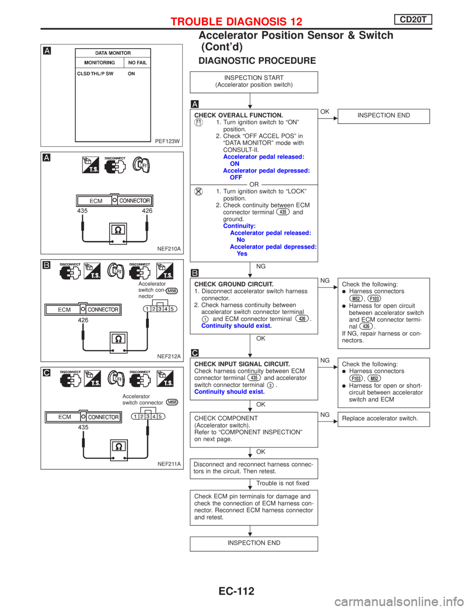
DIAGNOSTIC PROCEDURE
INSPECTION START
(Accelerator position switch)
CHECK OVERALL FUNCTION.1. Turn ignition switch to ªONº
position.
2. Check ªOFF ACCEL POSº in
ªDATA MONITORº mode with
CONSULT-II.
Accelerator pedal released:
ON
Accelerator pedal depressed:
OFF
-------------------------------------------------------------------------------------------------------------------------------OR-------------------------------------------------------------------------------------------------------------------------------
1. Turn ignition switch to ªLOCKº
position.
2. Check continuity between ECM
connector terminal
435and
ground.
Continuity:
Accelerator pedal released:
No
Accelerator pedal depressed:
Ye s
NG
EOK
INSPECTION END
CHECK GROUND CIRCUIT.
1. Disconnect accelerator switch harness
connector.
2. Check harness continuity between
accelerator switch connector terminal
p1and ECM connector terminal426.
Continuity should exist.
OK
ENG
Check the following:
lHarness connectorsM52,F103lHarness for open circuit
between accelerator switch
and ECM connector termi-
nal
426.
If NG, repair harness or con-
nectors.
CHECK INPUT SIGNAL CIRCUIT.
Check harness continuity between ECM
connector terminal
435and accelerator
switch connector terminal
p3.
Continuity should exist.
OK
ENG
Check the following:
lHarness connectorsF103,M52lHarness for open or short-
circuit between accelerator
switch and ECM
CHECK COMPONENT
(Accelerator switch).
Refer to ªCOMPONENT INSPECTIONº
on next page.
OK
ENG
Replace accelerator switch.
Disconnect and reconnect harness connec-
tors in the circuit. Then retest.
Trouble is not fixed
Check ECM pin terminals for damage and
check the connection of ECM harness con-
nector. Reconnect ECM harness connector
and retest.
INSPECTION END
PEF123W
NEF210A
NEF212A
Accelerator
switch con-
nector
NEF211A
Accelerator
switch connector
H
H
H
H
H
H
H
TROUBLE DIAGNOSIS 12CD20T
Accelerator Position Sensor & Switch
(Cont'd)
EC-112
Page 407 of 2267
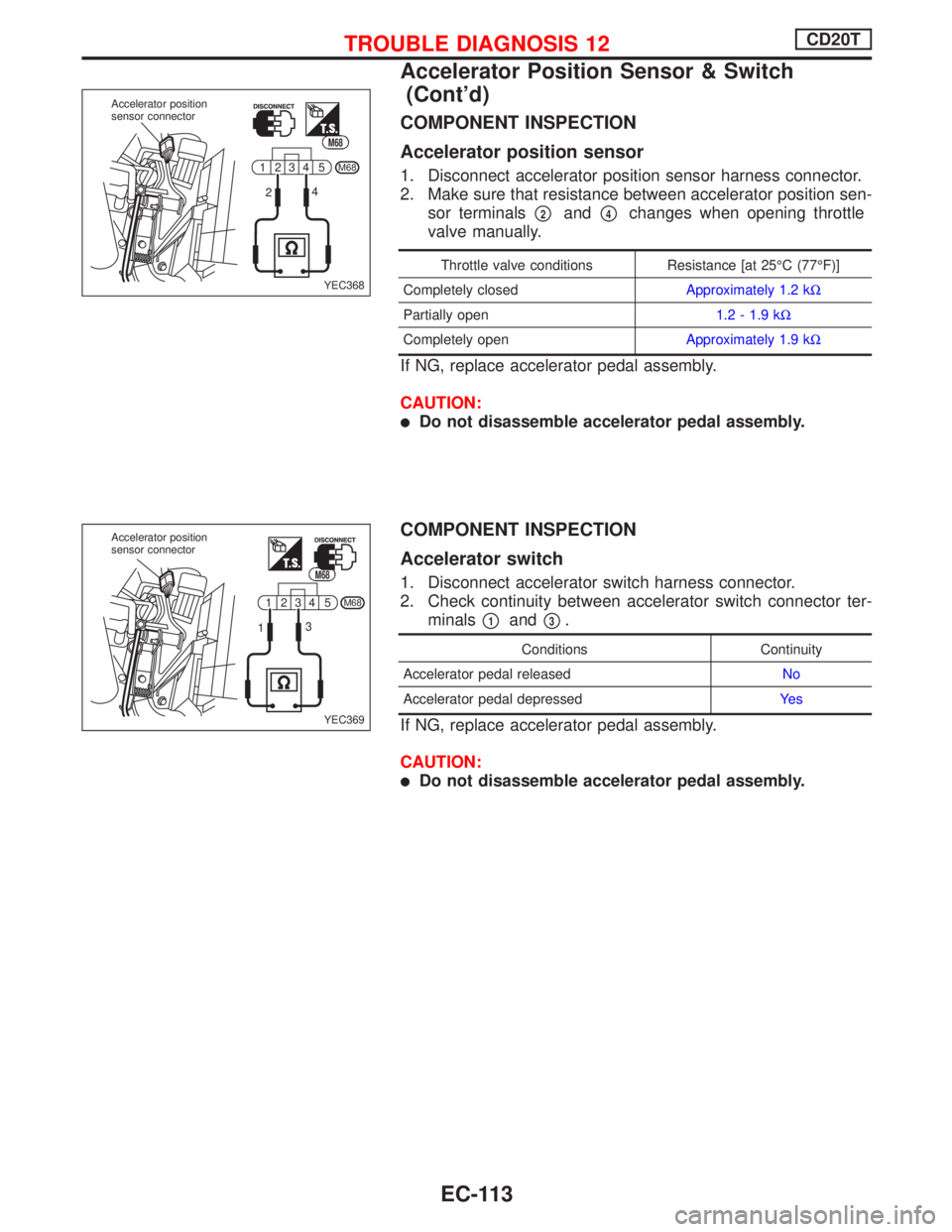
COMPONENT INSPECTION
Accelerator position sensor
1. Disconnect accelerator position sensor harness connector.
2. Make sure that resistance between accelerator position sen-
sor terminals
p2andp4changes when opening throttle
valve manually.
Throttle valve conditions Resistance [at 25ÉC (77ÉF)]
Completely closedApproximately 1.2 kW
Partially open1.2 - 1.9 kW
Completely openApproximately 1.9 kW
If NG, replace accelerator pedal assembly.
CAUTION:
lDo not disassemble accelerator pedal assembly.
COMPONENT INSPECTION
Accelerator switch
1. Disconnect accelerator switch harness connector.
2. Check continuity between accelerator switch connector ter-
minals
p1andp3.
Conditions Continuity
Accelerator pedal releasedNo
Accelerator pedal depressedYe s
If NG, replace accelerator pedal assembly.
CAUTION:
lDo not disassemble accelerator pedal assembly.
1
25 4 3M68
24
YEC368 Accelerator position
sensor connector
M68
1
25 4 3M68
13
YEC369 Accelerator position
sensor connector
M68
TROUBLE DIAGNOSIS 12CD20T
Accelerator Position Sensor & Switch
(Cont'd)
EC-113
Page 408 of 2267
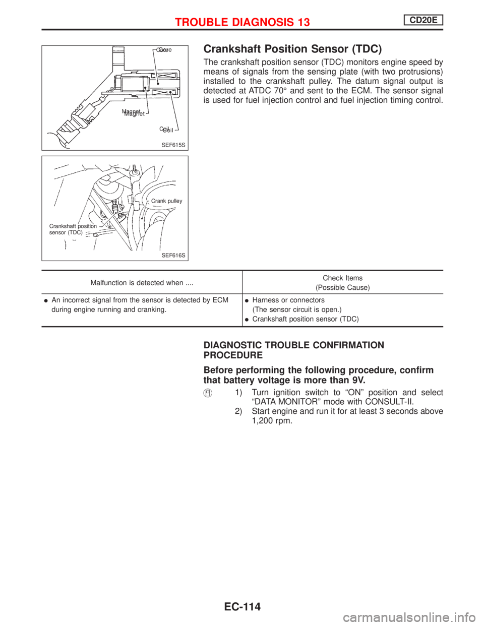
Crankshaft Position Sensor (TDC)
The crankshaft position sensor (TDC) monitors engine speed by
means of signals from the sensing plate (with two protrusions)
installed to the crankshaft pulley. The datum signal output is
detected at ATDC 70É and sent to the ECM. The sensor signal
is used for fuel injection control and fuel injection timing control.
Malfunction is detected when ....Check Items
(Possible Cause)
lAn incorrect signal from the sensor is detected by ECM
during engine running and cranking.lHarness or connectors
(The sensor circuit is open.)
lCrankshaft position sensor (TDC)
DIAGNOSTIC TROUBLE CONFIRMATION
PROCEDURE
Before performing the following procedure, confirm
that battery voltage is more than 9V.
1) Turn ignition switch to ªONº position and select
ªDATA MONITORº mode with CONSULT-II.
2) Start engine and run it for at least 3 seconds above
1,200 rpm.
SEF615S Core
Magnet
Coil
SEF616S Crank pulley
Crankshaft position
sensor (TDC)
TROUBLE DIAGNOSIS 13CD20E
EC-114
Page 409 of 2267
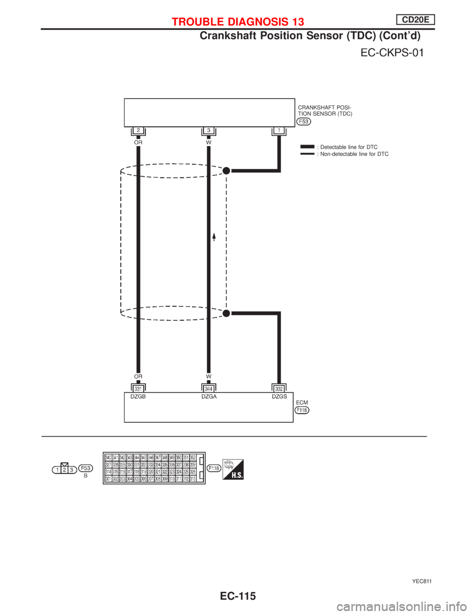
YEC811
CRANKSHAFT POSI-
TION SENSOR (TDC)
: Detectable line for DTC
: Non-detectable line for DTC
ECM
TROUBLE DIAGNOSIS 13CD20E
Crankshaft Position Sensor (TDC) (Cont'd)
EC-115
Page 410 of 2267
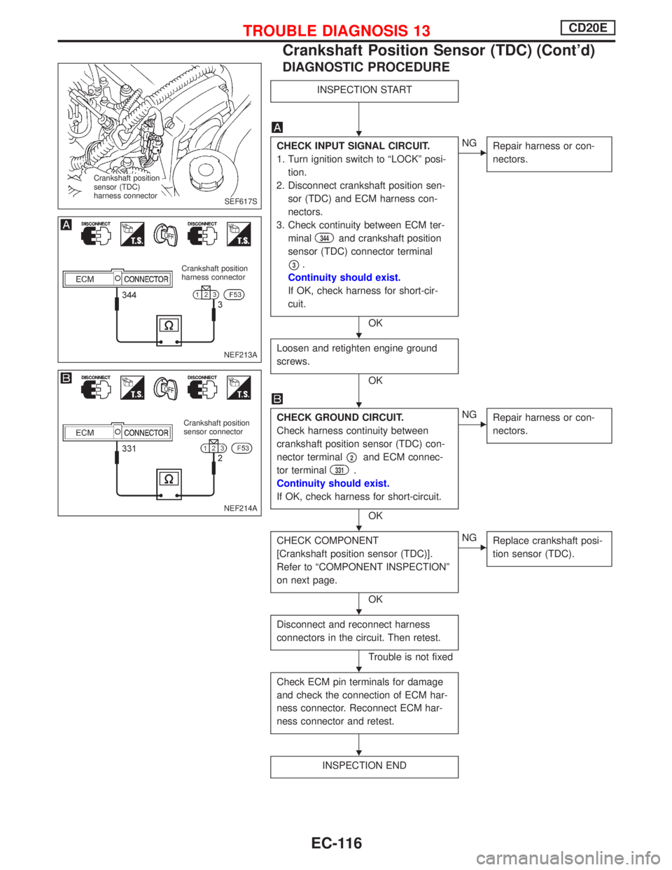
DIAGNOSTIC PROCEDURE
INSPECTION START
CHECK INPUT SIGNAL CIRCUIT.
1. Turn ignition switch to ªLOCKº posi-
tion.
2. Disconnect crankshaft position sen-
sor (TDC) and ECM harness con-
nectors.
3. Check continuity between ECM ter-
minal
344and crankshaft position
sensor (TDC) connector terminal
p3.
Continuity should exist.
If OK, check harness for short-cir-
cuit.
OK
ENG
Repair harness or con-
nectors.
Loosen and retighten engine ground
screws.
OK
CHECK GROUND CIRCUIT.
Check harness continuity between
crankshaft position sensor (TDC) con-
nector terminal
p2and ECM connec-
tor terminal
331.
Continuity should exist.
If OK, check harness for short-circuit.
OK
ENG
Repair harness or con-
nectors.
CHECK COMPONENT
[Crankshaft position sensor (TDC)].
Refer to ªCOMPONENT INSPECTIONº
on next page.
OK
ENG
Replace crankshaft posi-
tion sensor (TDC).
Disconnect and reconnect harness
connectors in the circuit. Then retest.
Trouble is not fixed
Check ECM pin terminals for damage
and check the connection of ECM har-
ness connector. Reconnect ECM har-
ness connector and retest.
INSPECTION END
SEF617S Crankshaft position
sensor (TDC)
harness connector
NEF213A
Crankshaft position
harness connector
NEF214A
Crankshaft position
sensor connector
H
H
H
H
H
H
H
TROUBLE DIAGNOSIS 13CD20E
Crankshaft Position Sensor (TDC) (Cont'd)
EC-116