lock NISSAN PRIMERA 1999 Electronic Service Manual
[x] Cancel search | Manufacturer: NISSAN, Model Year: 1999, Model line: PRIMERA, Model: NISSAN PRIMERA 1999Pages: 2267, PDF Size: 35.74 MB
Page 196 of 2267
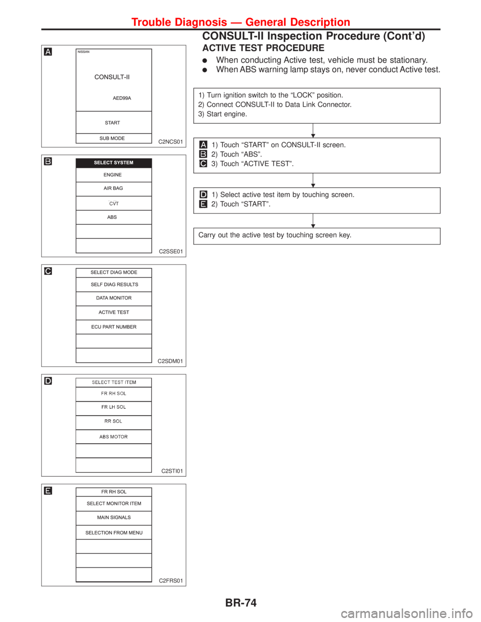
ACTIVE TEST PROCEDURE
lWhen conducting Active test, vehicle must be stationary.
lWhen ABS warning lamp stays on, never conduct Active test.
1) Turn ignition switch to the ªLOCKº position.
2) Connect CONSULT-II to Data Link Connector.
3) Start engine.
1) Touch ªSTARTº on CONSULT-II screen.
2) Touch ªABSº.
3) Touch ªACTIVE TESTº.
1) Select active test item by touching screen.
2) Touch ªSTARTº.
Carry out the active test by touching screen key.
C2NCS01
C2SSE01
.CVT
C2SDM01
C2STI01
C2FRS01
H
H
H
Trouble Diagnosis Ð General Description
CONSULT-II Inspection Procedure (Cont'd)
BR-74
Page 219 of 2267
Body Front End
lWhen removing or installing hood, place a cloth or other padding on the front fender panels and cowl
top. This prevents vehicle body from being scratched.
lBumper fascia is made of plastic. Do not use excessive force and be sure to keep oil away from it.
lHood adjustment: Adjust at hinge portion.
lHood lock adjustment: After adjusting, check hood lock control operation. Apply a coat of grease to hood
locks engaging mechanism.
lHood opener: Do not attempt to bend cable forcibly. Doing so increases effort required to unlock hood.
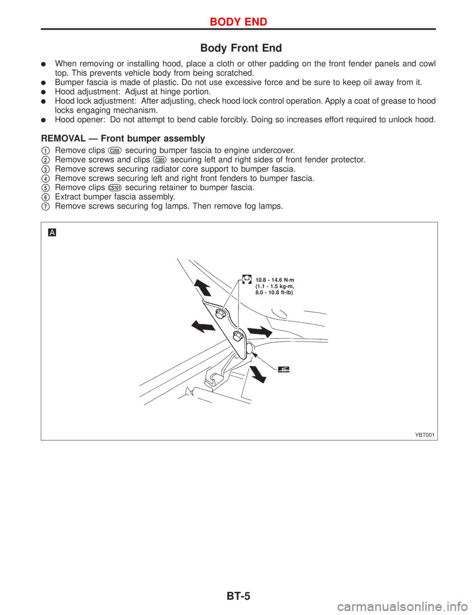
REMOVAL Ð Front bumper assembly
p1Remove clipsC205securing bumper fascia to engine undercover.
p2Remove screws and clipsC205securing left and right sides of front fender protector.
p3Remove screws securing radiator core support to bumper fascia.
p4Remove screws securing left and right front fenders to bumper fascia.
p5Remove clipsCS101securing retainer to bumper fascia.
p6Extract bumper fascia assembly.
p7Remove screws securing fog lamps. Then remove fog lamps.
YBT001
10.8 - 14.6 N´m
(1.1 - 1.5 kg-m,
8.0 - 10.8 ft-lb)
BODY END
BT-5
Page 220 of 2267

NBT033
SEC. 261×620×623×650×656
Hood lock adjustmentlAdjust hood so that hood primary lock
meshes at a position 1 to 1.5 mm (0.039 to
0.059 in) lower than fender.
lAfter hood lock adjustment, adjust bumper
rubber.
lWhen securing hood lock, ensure it does not
tilt. Striker must be positioned at the center of
hood primary lock.
lAfter adjustment, ensure that hood primary and sec-
ondary lock operate properly.
More than 5.0 mm (0.197 in)
Hood
Secondary latch
Bumper rubber adjustment
lAdjust so that hood is aligned
with fender. At that time deflection
is approx. 2 mm (0.08 in).
[Bumper rubber free height is
approx. 13 mm (0.51 in).]Hood adjustment
20.6 - 26.5
(2.1 - 2.7,
15 - 20)
Bumper fascia assembly
H: Bumper assembly mounting bolts, screw & clips
: N´m (kg-m, ft-lb)Fog lamp
CS101
HH
C205
C205
H
H
H
.Hood lock secondary latch hooking length
BODY END
Body Front End (Cont'd)
BT-6
Page 221 of 2267
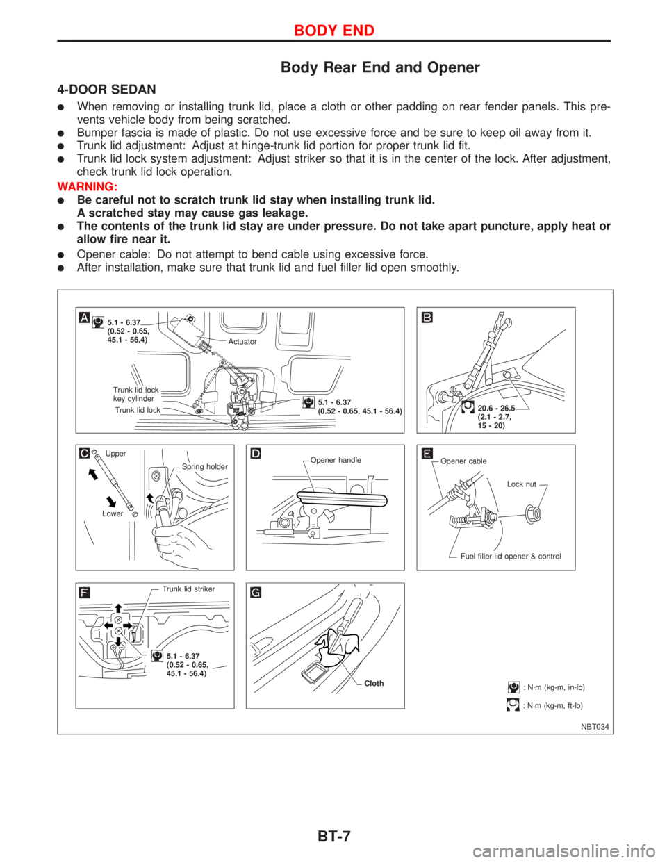
Body Rear End and Opener
4-DOOR SEDAN
lWhen removing or installing trunk lid, place a cloth or other padding on rear fender panels. This pre-
vents vehicle body from being scratched.
lBumper fascia is made of plastic. Do not use excessive force and be sure to keep oil away from it.
lTrunk lid adjustment: Adjust at hinge-trunk lid portion for proper trunk lid fit.
lTrunk lid lock system adjustment: Adjust striker so that it is in the center of the lock. After adjustment,
check trunk lid lock operation.
WARNING:
lBe careful not to scratch trunk lid stay when installing trunk lid.
A scratched stay may cause gas leakage.
lThe contents of the trunk lid stay are under pressure. Do not take apart puncture, apply heat or
allow fire near it.
lOpener cable: Do not attempt to bend cable using excessive force.
lAfter installation, make sure that trunk lid and fuel filler lid open smoothly.
NBT034
5.1 - 6.37
(0.52 - 0.65,
45.1 - 56.4)
Upper
Spring holder
LowerOpener handle
Opener cable
Lock nut
Fuel filler lid opener & control
Trunk lid striker
.5.1 - 6.37
(0.52 - 0.65,
45.1 - 56.4)
: N´m (kg-m, ft-lb)
20.6 - 26.5
(2.1 - 2.7,
15 - 20)
: N´m (kg-m, in-lb) Cloth
Actuator
.Trunk lid lock
key cylinder
.Trunk lid lock
.5.1 - 6.37
(0.52 - 0.65, 45.1 - 56.4)
BODY END
BT-7
Page 223 of 2267
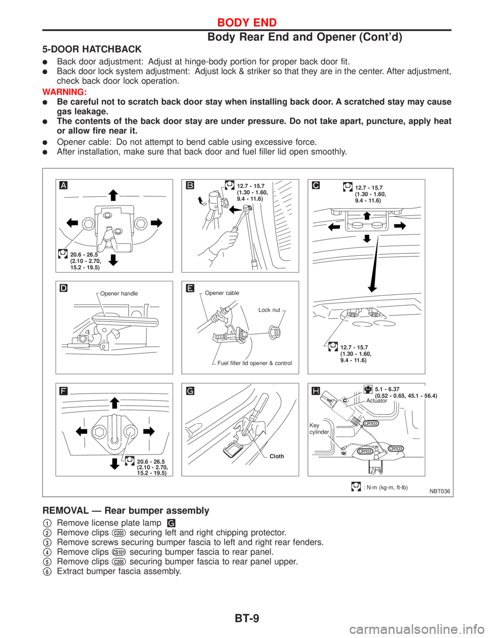
5-DOOR HATCHBACK
lBack door adjustment: Adjust at hinge-body portion for proper back door fit.
lBack door lock system adjustment: Adjust lock & striker so that they are in the center. After adjustment,
check back door lock operation.
WARNING:
lBe careful not to scratch back door stay when installing back door. A scratched stay may cause
gas leakage.
lThe contents of the back door stay are under pressure. Do not take apart, puncture, apply heat
or allow fire near it.
lOpener cable: Do not attempt to bend cable using excessive force.
lAfter installation, make sure that back door and fuel filler lid open smoothly.
REMOVAL Ð Rear bumper assembly
p1Remove license plate lamp
p2Remove clipsC203securing left and right chipping protector.
p3Remove screws securing bumper fascia to left and right rear fenders.
p4Remove clipsCS101securing bumper fascia to rear panel.
p5Remove clipsC205securing bumper fascia to rear panel upper.
p6Extract bumper fascia assembly.
NBT036 Opener handleOpener cable
Lock nut
Fuel filler lid opener & control
20.6 - 26.5
(2.10 - 2.70,
15.2 - 19.5)
12.7 - 15.7
(1.30 - 1.60,
9.4 - 11.6)12.7 - 15.7
(1.30 - 1.60,
9.4 - 11.6)
12.7 - 15.7
(1.30 - 1.60,
9.4 - 11.6)
20.6 - 26.5
(2.10 - 2.70,
15.2 - 19.5)
: N´m (kg-m, ft-lb) Cloth
.5.1 - 6.37
(0.52 - 0.65, 45.1 - 56.4)
Actuator
Key
cylinder
BODY END
Body Rear End and Opener (Cont'd)
BT-9
Page 225 of 2267
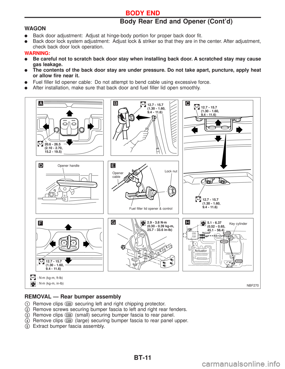
WAGON
lBack door adjustment: Adjust at hinge-body portion for proper back door fit.
lBack door lock system adjustment: Adjust lock & striker so that they are in the center. After adjustment,
check back door lock operation.
WARNING:
lBe careful not to scratch back door stay when installing back door. A scratched stay may cause
gas leakage.
lThe contents of the back door stay are under pressure. Do not take apart, puncture, apply heat
or allow fire near it.
lFuel filler lid opener cable: Do not attempt to bend cable using excessive force.
lAfter installation, make sure that back door and fuel filler lid open smoothly.
REMOVAL Ð Rear bumper assembly
p1Remove clipsC203securing left and right chipping protector.
p2Remove screws securing bumper fascia to left and right rear fenders.
p3Remove clipsC205(small) securing bumper fascia to rear panel.
p4Remove clipsC205(large) securing bumper fascia to rear panel upper.
p5Extract bumper fascia assembly.
NBF270 Opener handle
Opener
cableLock nut
.Fuel filler lid opener & control
.20.6 - 26.5
(2.10 - 2.70,
15.2 - 19.5)
12.7 - 15.7
(1.30 - 1.60,
9.4 - 11.6)12.7 - 15.7
(1.30 - 1.60,
9.4 - 11.6)
12.7 - 15.7
(1.30 - 1.60,
9.4 - 11.6)
.12.7 - 15.7
(1.30 - 1.60,
9.4 - 11.6)
: N´m (kg-m, ft-lb)
: N´m (kg-m, in-lb)
2.9 - 3.8 N´m
(0.30 - 0.39 kg-m,
25.7 - 33.6 in-lb)..5.1 - 6.37
(0.52 - 0.65,
45.1 - 56.4)Key cylinder
Actuator
BODY END
Body Rear End and Opener (Cont'd)
BT-11
Page 226 of 2267
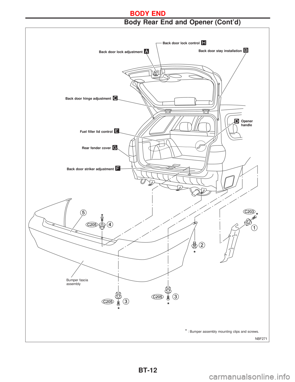
NBF271 Back door lock adjustment
Back door hinge adjustment
Back door stay installation
Opener
handle
Fuel filler lid control
Back door striker adjustment
*: Bumper assembly mounting clips and screws. Bumper fascia
assemblyRear fender cover
Back door lock control
BODY END
Body Rear End and Opener (Cont'd)
BT-12
Page 227 of 2267

Front Door
lFor removal of door trim, refer to ªDoor Trimº in ªINTERIOR TRIMº for details, BT-24.
lAfter adjusting door or door lock, check door lock operation.
NBT038
SEC. 800×803×805
5.1 - 6.37
(0.52 - 0.65, 45.1 - 56.4)
5.1 - 6.37
(0.52 - 0.65,
45.1 - 56.4)
6.08 - 7.75
(0.62 - 0.79,
53.8 - 68.6)
6.08 - 7.75
(0.62 - 0.79,
53.8 - 68.6)
6.08 - 7.75
(0.62 - 0.79,
53.8 - 68.6)6.08 - 7.75
(0.62 - 0.79,
53.8 - 68.6)
20.6 - 26.5
(2.1 - 2.7,
15 - 20)
5.1 - 6.37
(0.52 - 0.65,
45.1 - 56.4)
2.93 - 3.82
(0.30 - 0.39,
25.9 - 33.8)
Door-hinge adjustment
20.6 - 26.5 (2.1 - 2.7, 15 - 20)
: N´m (kg-m, ft-lb)
: N´m (kg-m, in-lb)
: Apply grease Striker adjustment
13-16
(1.3 - 1.6,
9 - 12)Door-hinge
adjustment
DOOR
BT-13
Page 275 of 2267
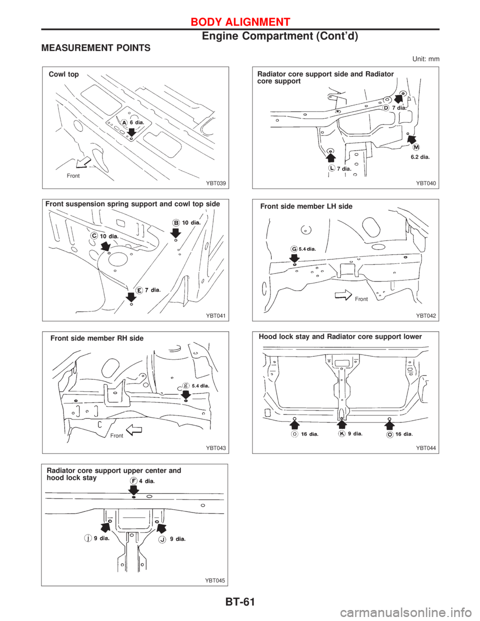
MEASUREMENT POINTS
Unit: mm
YBT039 Front
Cowl top
YBT041
.Front suspension spring support and cowl top side
.YBT043
Front side member RH side
Front
YBT045
Radiator core support upper center and
hood lock stay
YBT040
Radiator core support side and Radiator
core support
7 dia.
6.2 dia.
7 dia.
YBT042 Front
Front side member LH side
YBT044
Hood lock stay and Radiator core support lower
BODY ALIGNMENT
Engine Compartment (Cont'd)
BT-61
Page 284 of 2267
INSPECITON
Pedal stroke
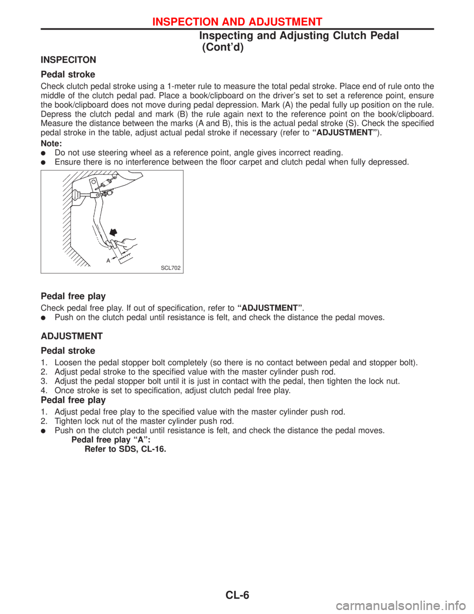
Check clutch pedal stroke using a 1-meter rule to measure the total pedal stroke. Place end of rule onto the
middle of the clutch pedal pad. Place a book/clipboard on the driver's set to set a reference point, ensure
the book/clipboard does not move during pedal depression. Mark (A) the pedal fully up position on the rule.
Depress the clutch pedal and mark (B) the rule again next to the reference point on the book/clipboard.
Measure the distance between the marks (A and B), this is the actual pedal stroke (S). Check the specified
pedal stroke in the table, adjust actual pedal stroke if necessary (refer toªADJUSTMENTº).
Note:
lDo not use steering wheel as a reference point, angle gives incorrect reading.
lEnsure there is no interference between the floor carpet and clutch pedal when fully depressed.
Pedal free play
Check pedal free play. If out of specification, refer toªADJUSTMENTº.
lPush on the clutch pedal until resistance is felt, and check the distance the pedal moves.
ADJUSTMENT
Pedal stroke
1. Loosen the pedal stopper bolt completely (so there is no contact between pedal and stopper bolt).
2. Adjust pedal stroke to the specified value with the master cylinder push rod.
3. Adjust the pedal stopper bolt until it is just in contact with the pedal, then tighten the lock nut.
4. Once stroke is set to specification, adjust clutch pedal free play.
Pedal free play
1. Adjust pedal free play to the specified value with the master cylinder push rod.
2. Tighten lock nut of the master cylinder push rod.
lPush on the clutch pedal until resistance is felt, and check the distance the pedal moves.
Pedal free play ªAº:
Refer to SDS, CL-16.
SCL702
INSPECTION AND ADJUSTMENT
Inspecting and Adjusting Clutch Pedal
(Cont'd)
CL-6