Control NISSAN PRIMERA 1999 Electronic Repair Manual
[x] Cancel search | Manufacturer: NISSAN, Model Year: 1999, Model line: PRIMERA, Model: NISSAN PRIMERA 1999Pages: 2267, PDF Size: 35.74 MB
Page 1 of 2267
Edition:May 2001
GENERA LINFORMATIONGI
MAINTENANCEMA
ENGIN EMECHANICALEM
ENGIN ELUBRICATIO N&LC
ENGIN ECONTRO LSYSTEMQG16/18DE
ENGIN ECONTRO LSYSTEMSR20DE
ENGIN ECONTRO LSYSTEMCD20T
ACCELERATO RCONTROL,FE
CLUTCHCL
MANUA LTRANSAXLEMT
AUTOMATI CTRANSAXLEAT
FRON TAXL E& FRON TSUSPENSIONFA
REA RAXL E& REA RSUSPENSIONRA
BRAK ESYSTEMBR
STEERIN GSYSTEMST
RESTRAIN TSYSTEMRS
BOD Y& TRIMBT
HEATE R&AIR CONDITIONERHA
ELECTRICA LSYSTEMEL
ALPHABETICA LINDEXIDX
PRIMERA
NISSA NEUROP EN.V.
Page 3 of 2267
AUTOMATIC TRANSAXLE
SECTION
AT(H×CVT)
CONTENTS
TROUBLE DIAGNOSIS - INDEX....................................3
Alphabetical & P No. Index for DTC ...........................3
PRECAUTIONS...............................................................5
Precautions for Supplemental Restraint System
(SRS)²AIR BAG²and²SEAT BELT
PRE-TENSIONER²......................................................5
Precautions for On Board Diagnostic (OBD)
System of CVT and Engine .........................................5
Precautions ..................................................................5
Service Notice or Precautions .....................................6
Wiring Diagrams and Trouble Diagnosis .....................7
PREPARATION...............................................................8
Special Service Tools ..................................................8
OVERALL SYSTEM........................................................9
CVT Electrical Parts Location......................................9
Circuit Diagram ..........................................................10
Cross-sectional View - RE0F06A .............................. 11
Control System ..........................................................12
ON BOARD DIAGNOSTIC SYSTEM
DESCRIPTION...............................................................15
Introduction ................................................................15
OBD Function for CVT System .................................15
OBD Diagnostic Trouble Code (DTC) .......................15
Malfunction Indicator (MI) ..........................................18
CONSULT-II ...............................................................18
TROUBLE DIAGNOSIS - INTRODUCTION..................29
Introduction ................................................................29
Work Flow ..................................................................32
TROUBLE DIAGNOSIS - BASIC INSPECTION...........34
CVT Fluid Check .......................................................34
Stall Test ....................................................................34
Line Pressure Test .....................................................35
Road Test...................................................................36
TROUBLE DIAGNOSIS - GENERAL
DESCRIPTION...............................................................41
TCM Terminals and Reference Value........................41TROUBLE DIAGNOSIS FOR POWER SUPPLY..........45
Wiring Diagram - CVT - MAIN...................................45
DTC P0705 PARK/NEUTRAL POSITION (PNP)
SWITCH.........................................................................48
Description .................................................................48
Wiring Diagram - AT - PNP/SW.................................50
Diagnostic Procedure ................................................51
Component Inspection ...............................................53
DTC P0710 CVT FLUID TEMPERATURE SENSOR
CIRCUIT.........................................................................54
Description .................................................................54
Wiring Diagram - AT - FTS ........................................56
Diagnostic Procedure ................................................57
DTC P0715 PRIMARY SPEED SENSOR.....................59
Description .................................................................59
Wiring Diagram - AT - VSSA/T ..................................60
Diagnostic Procedure ................................................61
Component Inspection ...............................................61
DTC P0720 VEHICLE SPEED SENSOR CVT
(SECONDARY SPEED SENSOR)................................62
Description .................................................................62
Wiring Diagram - AT - VSSA/T ..................................64
Diagnostic Procedure ................................................65
Component Inspection ...............................................65
DTC P0725 ENGINE SPEED SIGNAL.........................66
Description .................................................................66
Wiring Diagram - AT - ENGSS ..................................67
Diagnostic Procedure ................................................68
DTC P0740 TORQUE CONVERTER CLUTCH
SOLENOID VALVE........................................................69
Description .................................................................69
Wiring Diagram - AT - TCV........................................71
Diagnostic Procedure ................................................72
Component Inspection ...............................................73
DTC P0745 LINE PRESSURE SOLENOID VALVE.....74
Description .................................................................74
AT
Page 4 of 2267
Wiring Diagram - AT - LPSV......................................76
Diagnostic Procedure ................................................77
Component Inspection ...............................................78
DTC P1705 THROTTLE POSITION SENSOR.............79
Description .................................................................79
Wiring Diagram - AT - TPS ........................................81
Diagnostic Procedure ................................................82
Component Inspection ...............................................85
DTC P1777 STEP MOTOR - CIRCUIT.........................86
Description .................................................................86
Wiring Diagram - AT - STM .......................................88
Diagnostic Procedure ................................................89
Component Inspection ...............................................90
DTC P1778 STEP MOTOR - FUNCTION.....................91
Description .................................................................91
Diagnostic Procedure ................................................93
DTC P1791 CVT FLUID PRESSURE SENSOR...........94
Description .................................................................94
Wiring Diagram - AT - FPS ........................................96
Diagnostic Procedure ................................................97
Component Inspection ...............................................98
CVT SAFE FUNCTION..................................................99
Description .................................................................99
Diagnostic Procedure ..............................................100
CONTROL UNIT (RAM), CONTROL UNIT (ROM).....101
Description ...............................................................101Diagnostic Procedure ..............................................102
CONTROL UNIT (EEPROM).......................................103
Description ...............................................................103
Diagnostic Procedure ..............................................104
TROUBLE DIAGNOSES FOR NON-DETECTABLE
ITEMS...........................................................................105
PNP Switch, Stop Lamp Switch and Throttle
Position Switch ........................................................105
Wiring Diagram - AT - NONDTC ............................. 110
ON-VEHICLE SERVICE.............................................. 114
Control Cable Adjustment ........................................ 114
Park/Neutral Position (PNP) Switch Adjustment ..... 114
Differential Side Oil Seal Replacement ................... 114
REMOVAL AND INSTALLATION............................... 116
Removal ................................................................... 116
Inspection................................................................. 116
Installation ................................................................ 117
Air Breather Hose .................................................... 118
CVT Fluid Cooler (Hyper CVT-M6) ......................... 118
Components............................................................. 119
SERVICE DATA AND SPECIFICATIONS (SDS).......120
General Specifications .............................................120
Stall Revolution ........................................................120
Line Pressure...........................................................120
Removal and Installation .........................................120
CONTENTS(Cont'd)
AT-2
Page 5 of 2267
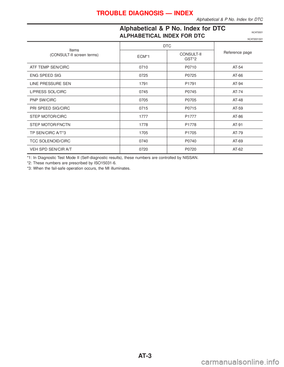
Alphabetical & P No. Index for DTCNCAT0001ALPHABETICAL INDEX FOR DTCNCAT0001S01
Items
(CONSULT-II screen terms)DTC
Reference page
ECM*1CONSULT-II
GST*2
ATF TEMP SEN/CIRC 0710 P0710 AT-54
ENG SPEED SIG 0725 P0725 AT-66
LINE PRESSURE SEN 1791 P1791 AT-94
L/PRESS SOL/CIRC 0745 P0745 AT-74
PNP SW/CIRC 0705 P0705 AT-48
PRI SPEED SIG/CIRC 0715 P0715 AT-59
STEP MOTOR/CIRC 1777 P1777 AT-86
STEP MOTOR/FNCTN 1778 P1778 AT-91
TP SEN/CIRC A/T*3 1705 P1705 AT-79
TCC SOLENOID/CIRC 0740 P0740 AT-69
VEH SPD SEN/CIR A/T 0720 P0720 AT-62
*1: In Diagnostic Test Mode II (Self-diagnostic results), these numbers are controlled by NISSAN.
*2: These numbers are prescribed by ISO15031-6.
*3: When the fail-safe operation occurs, the MI illuminates.
TROUBLE DIAGNOSIS Ð INDEX
Alphabetical & P No. Index for DTC
AT-3
Page 6 of 2267
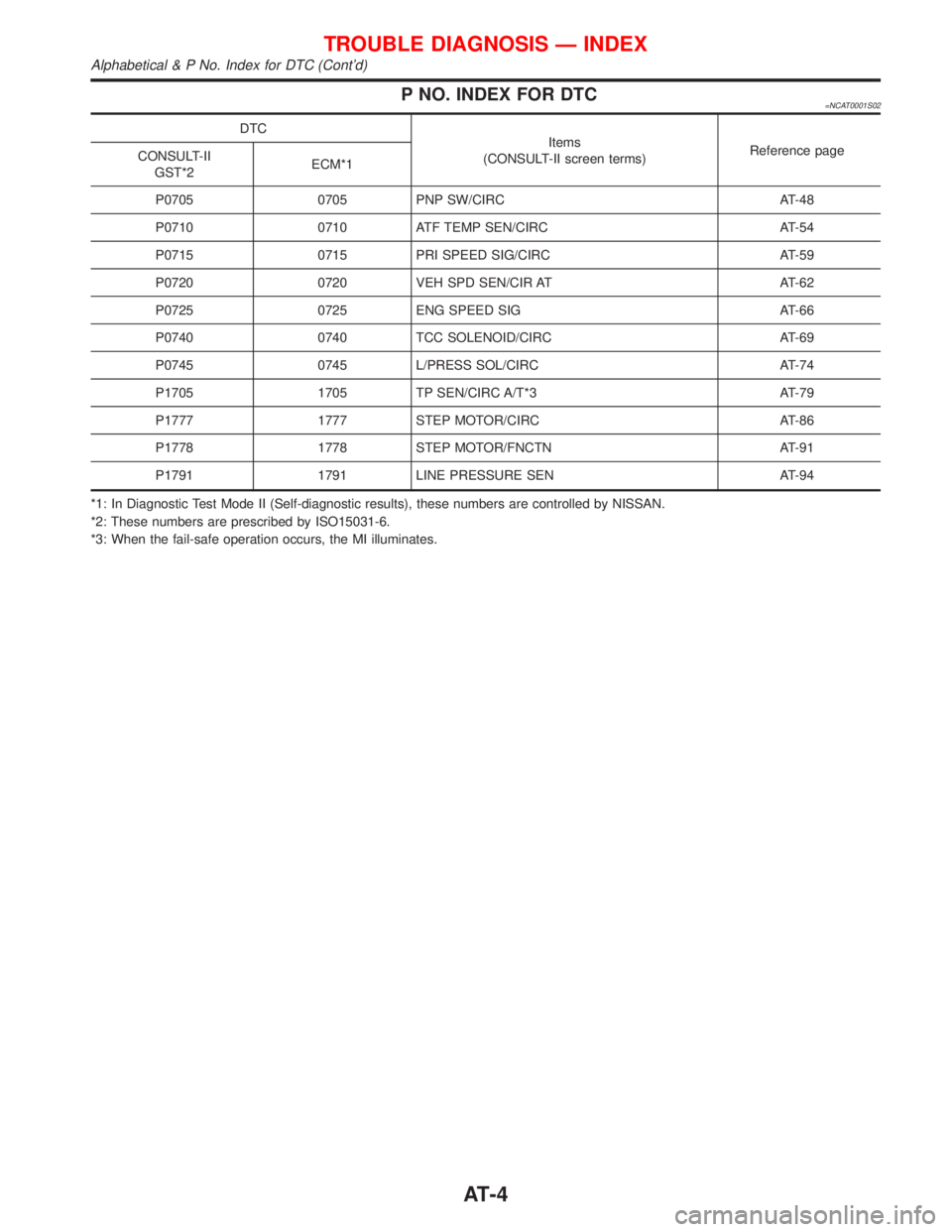
P NO. INDEX FOR DTC=NCAT0001S02
DTC
Items
(CONSULT-II screen terms)Reference page
CONSULT-II
GST*2ECM*1
P0705 0705 PNP SW/CIRC AT-48
P0710 0710 ATF TEMP SEN/CIRC AT-54
P0715 0715 PRI SPEED SIG/CIRC AT-59
P0720 0720 VEH SPD SEN/CIR AT AT-62
P0725 0725 ENG SPEED SIG AT-66
P0740 0740 TCC SOLENOID/CIRC AT-69
P0745 0745 L/PRESS SOL/CIRC AT-74
P1705 1705 TP SEN/CIRC A/T*3 AT-79
P1777 1777 STEP MOTOR/CIRC AT-86
P1778 1778 STEP MOTOR/FNCTN AT-91
P1791 1791 LINE PRESSURE SEN AT-94
*1: In Diagnostic Test Mode II (Self-diagnostic results), these numbers are controlled by NISSAN.
*2: These numbers are prescribed by ISO15031-6.
*3: When the fail-safe operation occurs, the MI illuminates.
TROUBLE DIAGNOSIS Ð INDEX
Alphabetical & P No. Index for DTC (Cont'd)
AT-4
Page 11 of 2267
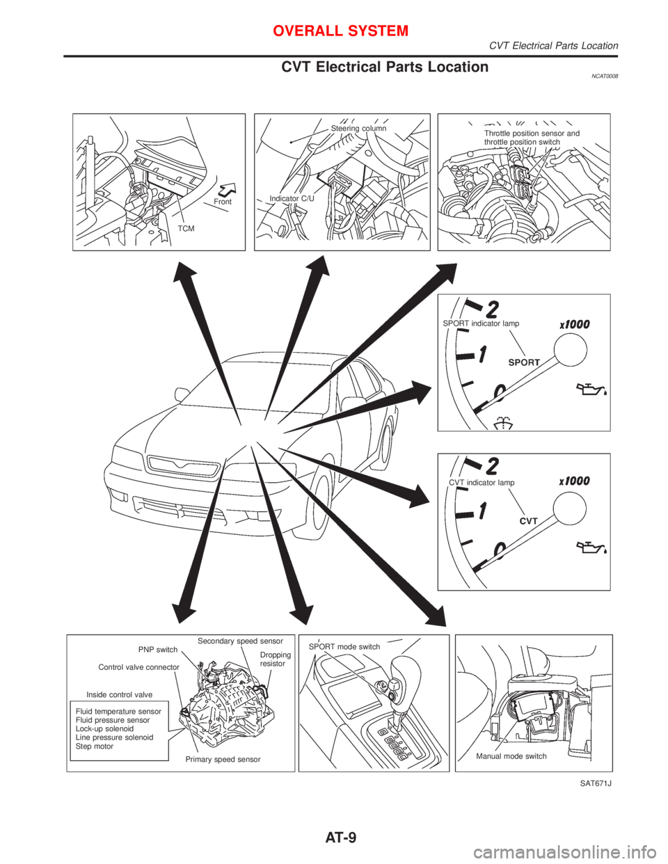
CVT Electrical Parts LocationNCAT0008
SAT671J Front
TCMIndicator C/USteering column
Throttle position sensor and
throttle position switch
SPORT indicator lamp
CVT indicator lamp
Manual mode switch SPORT mode switch
Dropping
resistor
Primary speed sensor Fluid temperature sensor
Fluid pressure sensor
Lock-up solenoid
Line pressure solenoid
Step motorInside control valveControl valve connectorPNP switchSecondary speed sensor
OVERALL SYSTEM
CVT Electrical Parts Location
AT-9
Page 14 of 2267
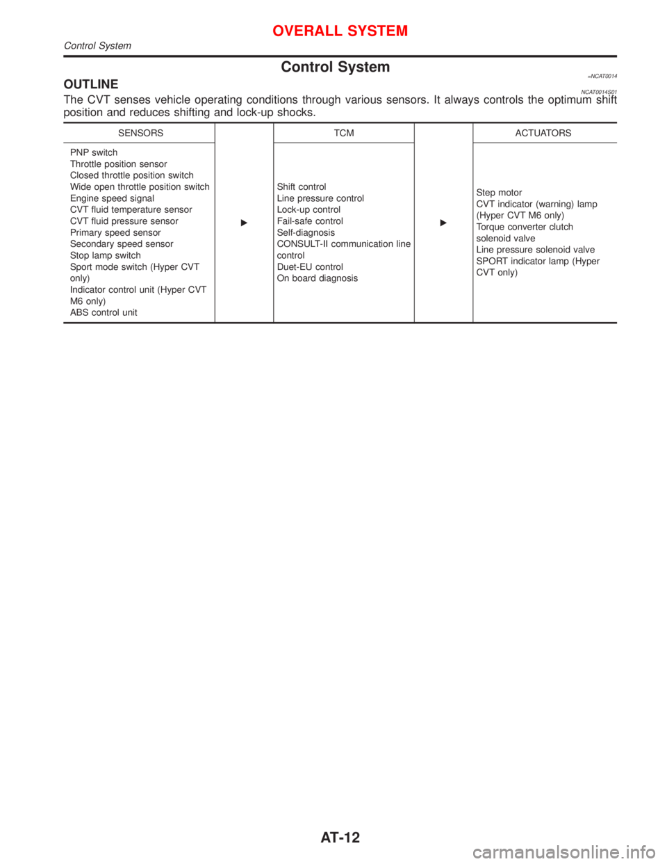
Control System=NCAT0014OUTLINENCAT0014S01The CVT senses vehicle operating conditions through various sensors. It always controls the optimum shift
position and reduces shifting and lock-up shocks.
SENSORS
ETCM
EACTUATORS
PNP switch
Throttle position sensor
Closed throttle position switch
Wide open throttle position switch
Engine speed signal
CVT fluid temperature sensor
CVT fluid pressure sensor
Primary speed sensor
Secondary speed sensor
Stop lamp switch
Sport mode switch (Hyper CVT
only)
Indicator control unit (Hyper CVT
M6 only)
ABS control unitShift control
Line pressure control
Lock-up control
Fail-safe control
Self-diagnosis
CONSULT-II communication line
control
Duet-EU control
On board diagnosisStep motor
CVT indicator (warning) lamp
(Hyper CVT M6 only)
Torque converter clutch
solenoid valve
Line pressure solenoid valve
SPORT indicator lamp (Hyper
CVT only)
OVERALL SYSTEM
Control System
AT-12
Page 15 of 2267
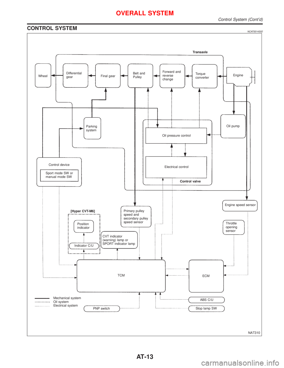
CONTROL SYSTEMNCAT0014S02
NAT310 WheelDifferential
gearFinal gearBelt and
PulleyForward and
reverse
changeTorque
converterEngine Transaxle
Oil pump
Oil pressure control Parking
system
Control device
Sport mode SW or
manual mode SWElectrical control
Control valve
Primary pulley
speed and
secondary pulley
speed sensor
CVT indicator
(warning) lamp or
SPORT indicator lamp [Hyper CVT-M6]
Position
indicator
Indicator C/U
TCM
Mechanical system
Oil system
Electrical system
Stop lamp SWABS C/UECMThrottle
opening
sensor Engine speed sensor
PNP switch
OVERALL SYSTEM
Control System (Cont'd)
AT-13
Page 16 of 2267
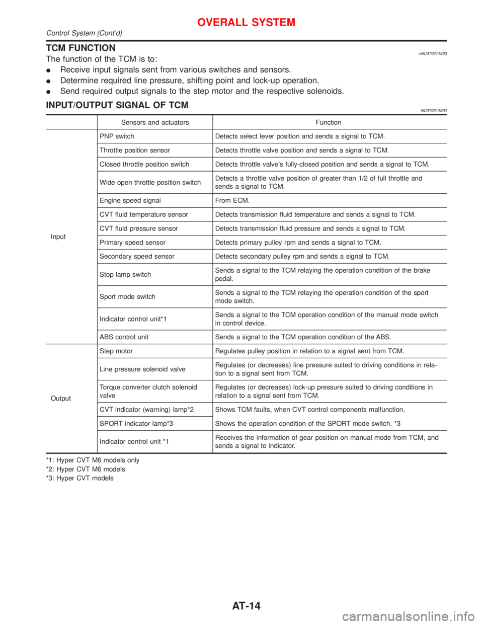
TCM FUNCTION=NCAT0014S03The function of the TCM is to:
IReceive input signals sent from various switches and sensors.
IDetermine required line pressure, shifting point and lock-up operation.
ISend required output signals to the step motor and the respective solenoids.
INPUT/OUTPUT SIGNAL OF TCMNCAT0014S04
Sensors and actuators Function
InputPNP switch Detects select lever position and sends a signal to TCM.
Throttle position sensor Detects throttle valve position and sends a signal to TCM.
Closed throttle position switch Detects throttle valve's fully-closed position and sends a signal to TCM.
Wide open throttle position switchDetects a throttle valve position of greater than 1/2 of full throttle and
sends a signal to TCM.
Engine speed signal From ECM.
CVT fluid temperature sensor Detects transmission fluid temperature and sends a signal to TCM.
CVT fluid pressure sensor Detects transmission fluid pressure and sends a signal to TCM.
Primary speed sensor Detects primary pulley rpm and sends a signal to TCM.
Secondary speed sensor Detects secondary pulley rpm and sends a signal to TCM.
Stop lamp switchSends a signal to the TCM relaying the operation condition of the brake
pedal.
Sport mode switchSends a signal to the TCM relaying the operation condition of the sport
mode switch.
Indicator control unit*1Sends a signal to the TCM operation condition of the manual mode switch
in control device.
ABS control unit Sends a signal to the TCM operation condition of the ABS.
OutputStep motor Regulates pulley position in relation to a signal sent from TCM.
Line pressure solenoid valveRegulates (or decreases) line pressure suited to driving conditions in rela-
tion to a signal sent from TCM.
Torque converter clutch solenoid
valveRegulates (or decreases) lock-up pressure suited to driving conditions in
relation to a signal sent from TCM.
CVT indicator (warning) lamp*2 Shows TCM faults, when CVT control components malfunction.
SPORT indicator lamp*3 Shows the operation condition of the SPORT mode switch. *3
Indicator control unit *1Receives the information of gear position on manual mode from TCM, and
sends a signal to indicator.
*1: Hyper CVT M6 models only
*2: Hyper CVT M6 models
*3: Hyper CVT models
OVERALL SYSTEM
Control System (Cont'd)
AT-14
Page 17 of 2267
IntroductionNCAT0017The CVT system has two self-diagnostic systems.
The first is the emission-related on board diagnostic system (OBD) performed by the TCM in combination with
the ECM. The malfunction is indicated by the MI (malfunction indicator) and is stored as a DTC in the ECM
memory but not the TCM memory.
The second is the TCM original self-diagnosis indicated by the CVT indicator (warning) lamp or SPORT indi-
cator lamp. The malfunction is stored in the TCM memory. The detected items are overlapped with OBD self-
diagnostic items. For detail, refer to AT-26.
OBD Function for CVT SystemNCAT0018The ECM provides emission-related on board diagnostic (OBD) functions for the CVT system. One function
is to receive a signal from the TCM used with OBD-related parts of the CVT system. The signal is sent to the
ECM when a malfunction occurs in the corresponding OBD-related part. The other function is to indicate a
diagnostic result by means of the MI (malfunction indicator) on the instrument panel. Sensors, switches and
solenoid valves are used as sensing elements.
The MI automatically illuminates in Two Trip Detection Logic when a malfunction is sensed in relation to CVT
system parts.
OBD Diagnostic Trouble Code (DTC)NCAT0020HOW TO READ DTC AND 1ST TRIP DTCNCAT0020S01DTC and 1st trip DTC can be read by the following methods.
1.(
No Tools)The number of blinks of the malfunction indicator in the Diagnostic Test Mode II (Self-Di-
agnostic Results) Examples: 0705, 0710, 0715, 0720, etc. For details, refer to EC section [ªMalfunction
Indicator (MI)º, ªON BOARD DIAGNOSTIC SYSTEM DESCRIPTIONº].
These DTCs are controlled by NISSAN.
2.(
with CONSULT-II orGST)CONSULT-II or GST (Generic Scan Tool) Examples: P0705, P0710,
P0720, P0725, etc.
These DTCs are prescribed by ISO15031-6.
(CONSULT-II also displays the malfunctioning component or system.)
I1st trip DTC No. is the same as DTC No.
IOutput of the diagnostic trouble code indicates that the indicated circuit has a malfunction.
However, in case of the Mode II and GST they do not indicate whether the malfunction is still
occurring or occurred in the past and returned to normal.
CONSULT-II can identify them as shown below. Therefore, using CONSULT-II (if available) is rec-
ommended.
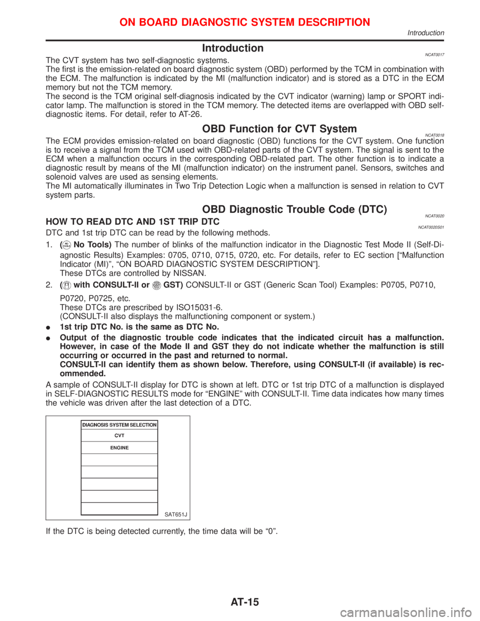
A sample of CONSULT-II display for DTC is shown at left. DTC or 1st trip DTC of a malfunction is displayed
in SELF-DIAGNOSTIC RESULTS mode for ªENGINEº with CONSULT-II. Time data indicates how many times
the vehicle was driven after the last detection of a DTC.
If the DTC is being detected currently, the time data will be ª0º.
SAT651J
ON BOARD DIAGNOSTIC SYSTEM DESCRIPTION
Introduction
AT-15