center console NISSAN PRIMERA 1999 Electronic Repair Manual
[x] Cancel search | Manufacturer: NISSAN, Model Year: 1999, Model line: PRIMERA, Model: NISSAN PRIMERA 1999Pages: 2267, PDF Size: 35.74 MB
Page 170 of 2267
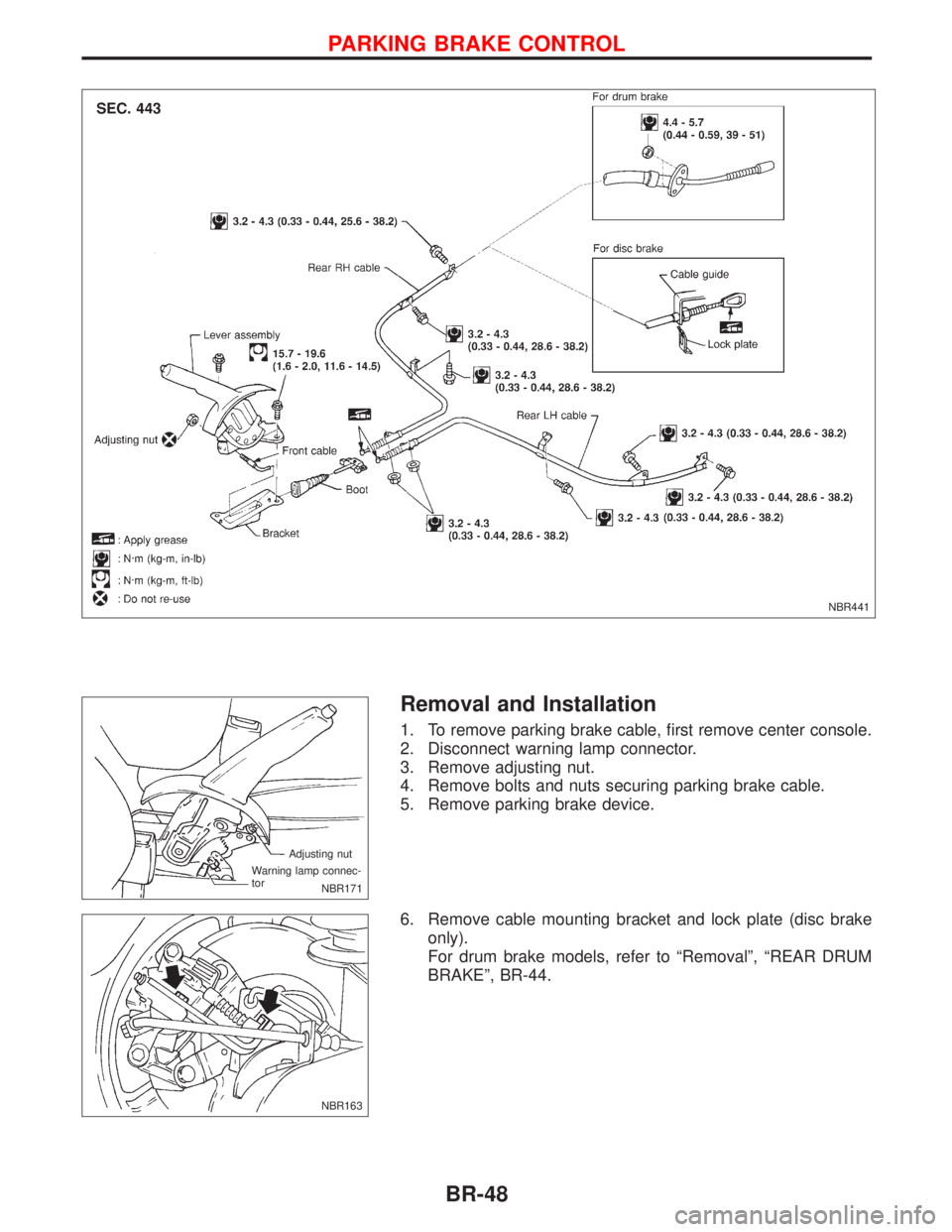
Removal and Installation
1. To remove parking brake cable, first remove center console.
2. Disconnect warning lamp connector.
3. Remove adjusting nut.
4. Remove bolts and nuts securing parking brake cable.
5. Remove parking brake device.
6. Remove cable mounting bracket and lock plate (disc brake
only).
For drum brake models, refer to ªRemovalº, ªREAR DRUM
BRAKEº, BR-44.
NBR441
NBR171 Adjusting nut
Warning lamp connec-
tor
NBR163
PARKING BRAKE CONTROL
BR-48
Page 229 of 2267
CAUTION:
lDisconnect both battery cables in advance.
lDisconnect air bag system line in advance.
lNever tamper with or force air bag lid open, as this may adversely affect air bag performance.
lBe careful not to scratch pad and other parts.
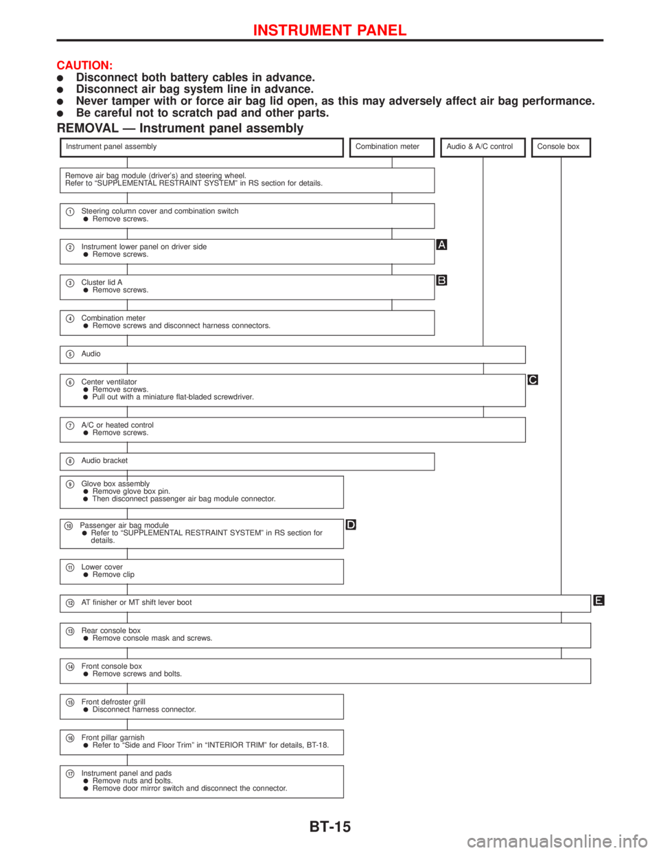
REMOVAL Ð Instrument panel assembly
Instrument panel assemblyCombination meterAudio & A/C controlConsole box
Remove air bag module (driver's) and steering wheel.
Refer to ªSUPPLEMENTAL RESTRAINT SYSTEMº in RS section for details.
p1Steering column cover and combination switchlRemove screws.
p2Instrument lower panel on driver sidelRemove screws.
p3Cluster lid AlRemove screws.
p4Combination meterlRemove screws and disconnect harness connectors.
p5Audio
p6Center ventilatorlRemove screws.lPull out with a miniature flat-bladed screwdriver.
p7A/C or heated controllRemove screws.
p8Audio bracket
p9Glove box assemblylRemove glove box pin.lThen disconnect passenger air bag module connector.
p10Passenger air bag modulelRefer to ªSUPPLEMENTAL RESTRAINT SYSTEMº in RS section for
details.
p11Lower coverlRemove clip
p12AT finisher or MT shift lever boot
p13Rear console boxlRemove console mask and screws.
p14Front console boxlRemove screws and bolts.
p15Front defroster grilllDisconnect harness connector.
p16Front pillar garnishlRefer to ªSide and Floor Trimº in ªINTERIOR TRIMº for details, BT-18.
p17Instrument panel and padslRemove nuts and bolts.lRemove door mirror switch and disconnect the connector.
INSTRUMENT PANEL
BT-15
Page 346 of 2267
ECM Terminals and Reference Value
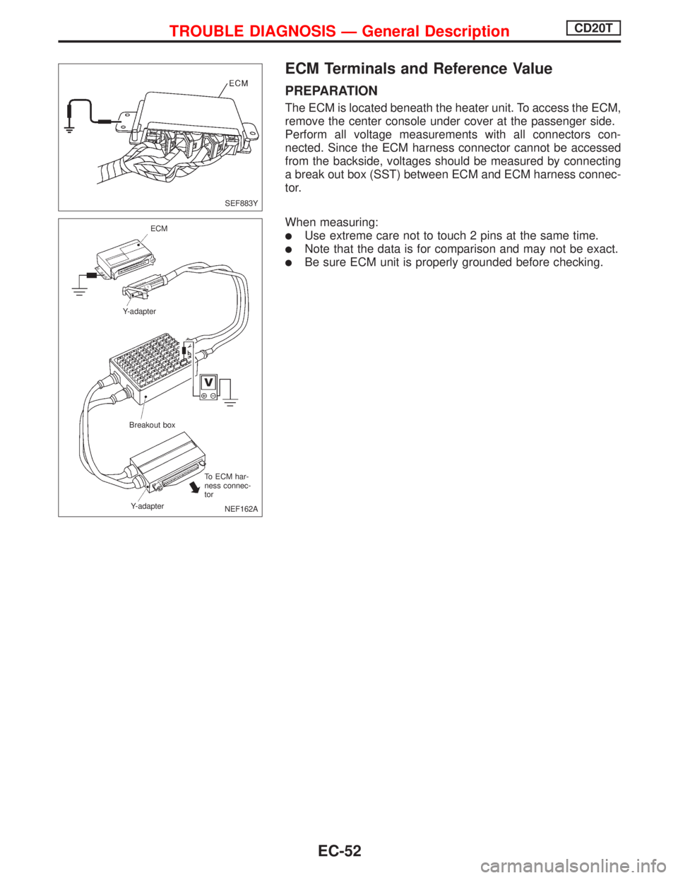
PREPARATION
The ECM is located beneath the heater unit. To access the ECM,
remove the center console under cover at the passenger side.
Perform all voltage measurements with all connectors con-
nected. Since the ECM harness connector cannot be accessed
from the backside, voltages should be measured by connecting
a break out box (SST) between ECM and ECM harness connec-
tor.
When measuring:
lUse extreme care not to touch 2 pins at the same time.
lNote that the data is for comparison and may not be exact.
lBe sure ECM unit is properly grounded before checking.
SEF883Y
NEF162A ECM
Y-adapter
Breakout box
Y-adapterTo ECM har-
ness connec-
tor
TROUBLE DIAGNOSIS Ð General DescriptionCD20T
EC-52
Page 533 of 2267
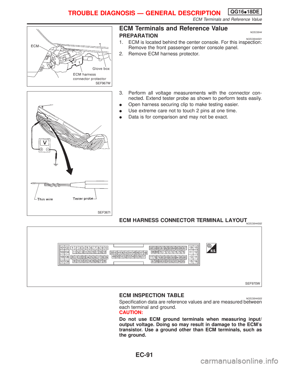
ECM Terminals and Reference ValueNCEC0044PREPARATIONNCEC0044S011. ECM is located behind the center console. For this inspection:
Remove the front passenger center console panel.
2. Remove ECM harness protector.
3. Perform all voltage measurements with the connector con-
nected. Extend tester probe as shown to perform tests easily.
IOpen harness securing clip to make testing easier.
IUse extreme care not to touch 2 pins at one time.
IData is for comparison and may not be exact.
ECM HARNESS CONNECTOR TERMINAL LAYOUTNCEC0044S02
ECM INSPECTION TABLENCEC0044S03Specification data are reference values and are measured between
each terminal and ground.
CAUTION:
Do not use ECM ground terminals when measuring input/
output voltage. Doing so may result in damage to the ECM's
transistor. Use a ground other than ECM terminals, such as
the ground.
SEF967W
SEF367I
SEF970W
TROUBLE DIAGNOSIS Ð GENERAL DESCRIPTIONQG16I18DE
ECM Terminals and Reference Value
EC-91
Page 903 of 2267
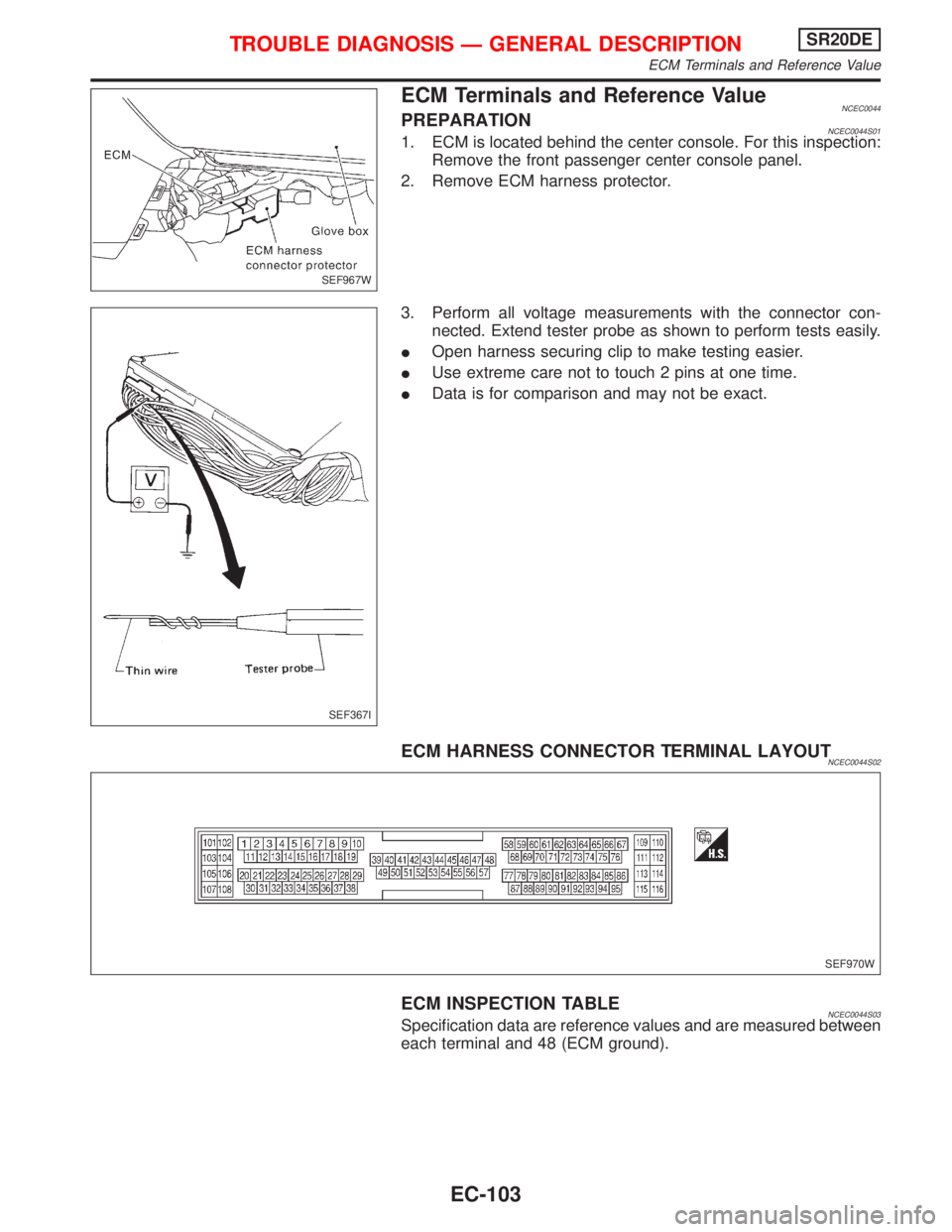
ECM Terminals and Reference ValueNCEC0044PREPARATIONNCEC0044S011. ECM is located behind the center console. For this inspection:
Remove the front passenger center console panel.
2. Remove ECM harness protector.
3. Perform all voltage measurements with the connector con-
nected. Extend tester probe as shown to perform tests easily.
IOpen harness securing clip to make testing easier.
IUse extreme care not to touch 2 pins at one time.
IData is for comparison and may not be exact.
ECM HARNESS CONNECTOR TERMINAL LAYOUTNCEC0044S02
ECM INSPECTION TABLENCEC0044S03Specification data are reference values and are measured between
each terminal and 48 (ECM ground).
SEF967W
SEF367I
SEF970W
TROUBLE DIAGNOSIS Ð GENERAL DESCRIPTIONSR20DE
ECM Terminals and Reference Value
EC-103