clock NISSAN PRIMERA 1999 Electronic Repair Manual
[x] Cancel search | Manufacturer: NISSAN, Model Year: 1999, Model line: PRIMERA, Model: NISSAN PRIMERA 1999Pages: 2267, PDF Size: 35.74 MB
Page 156 of 2267
lIt is not necessary to remove connecting bolt except for
disassembly or replacement of caliper assembly. In this
case, suspend cylinder body with wire so as not to
stretch brake hose.
lBurnish the brake contact surfaces after refinishing or
replacing rotors, after replacing pads, or if a soft pedal
occurs at very low mileage.
Refer to ªBrake Burnishing Procedureº, ªCHECK AND
ADJUSTMENTº, BR-7.
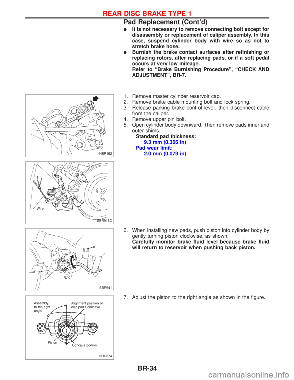
1. Remove master cylinder reservoir cap.
2. Remove brake cable mounting bolt and lock spring.
3. Release parking brake control lever, then disconnect cable
from the caliper.
4. Remove upper pin bolt.
5. Open cylinder body downward. Then remove pads inner and
outer shims.
Standard pad thickness:
9.3 mm (0.366 in)
Pad wear limit:
2.0 mm (0.079 in)
6. When installing new pads, push piston into cylinder body by
gently turning piston clockwise, as shown.
Carefully monitor brake fluid level because brake fluid
will return to reservoir when pushing back piston.
7. Adjust the piston to the right angle as shown in the figure.
NBR192
SBR916C Wire
SBR641
NBR374 Alignment position of
disc pad's concave
Concave portion Piston Assembly
to the right
angle
REAR DISC BRAKE TYPE 1
Pad Replacement (Cont'd)
BR-34
Page 157 of 2267
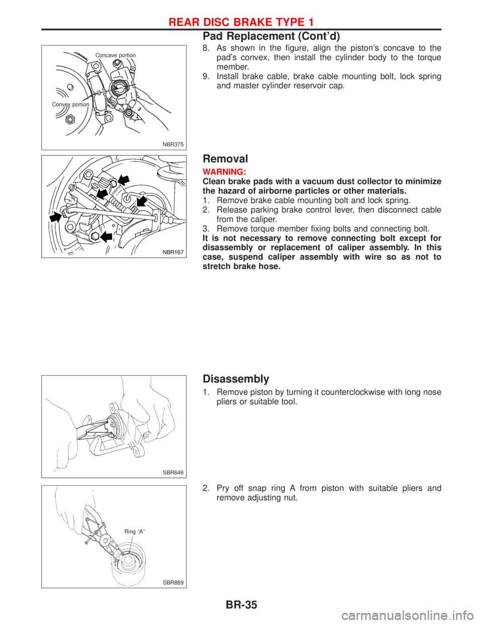
8. As shown in the figure, align the piston's concave to the
pad's convex, then install the cylinder body to the torque
member.
9. Install brake cable, brake cable mounting bolt, lock spring
and master cylinder reservoir cap.
Removal
WARNING:
Clean brake pads with a vacuum dust collector to minimize
the hazard of airborne particles or other materials.
1. Remove brake cable mounting bolt and lock spring.
2. Release parking brake control lever, then disconnect cable
from the caliper.
3. Remove torque member fixing bolts and connecting bolt.
It is not necessary to remove connecting bolt except for
disassembly or replacement of caliper assembly. In this
case, suspend caliper assembly with wire so as not to
stretch brake hose.
Disassembly
1. Remove piston by turning it counterclockwise with long nose
pliers or suitable tool.
2. Pry off snap ring A from piston with suitable pliers and
remove adjusting nut.
NBR375 Concave portion
Convex portion
NBR167
SBR646
SBR889 Ring ªAº
REAR DISC BRAKE TYPE 1
Pad Replacement (Cont'd)
BR-35
Page 161 of 2267
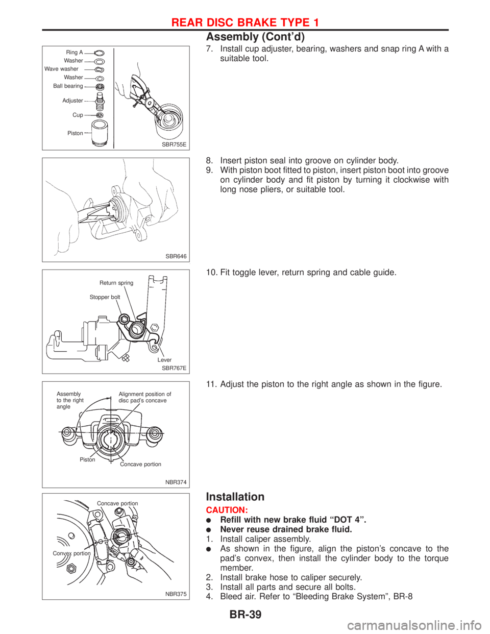
7. Install cup adjuster, bearing, washers and snap ring A with a
suitable tool.
8. Insert piston seal into groove on cylinder body.
9. With piston boot fitted to piston, insert piston boot into groove
on cylinder body and fit piston by turning it clockwise with
long nose pliers, or suitable tool.
10. Fit toggle lever, return spring and cable guide.
11. Adjust the piston to the right angle as shown in the figure.
Installation
CAUTION:
lRefill with new brake fluid ªDOT 4º.
lNever reuse drained brake fluid.
1. Install caliper assembly.
lAs shown in the figure, align the piston's concave to the
pad's convex, then install the cylinder body to the torque
member.
2. Install brake hose to caliper securely.
3. Install all parts and secure all bolts.
4. Bleed air. Refer to ªBleeding Brake Systemº, BR-8
SBR755E Ring A
Washer
Wave washer
Washer
Ball bearing
Adjuster
Cup
Piston
SBR646
SBR767E Stopper boltReturn spring
Lever
NBR374 Alignment position of
disc pad's concave
Concave portion Piston Assembly
to the right
angle
NBR375 Concave portion
Convex portion
REAR DISC BRAKE TYPE 1
Assembly (Cont'd)
BR-39
Page 163 of 2267
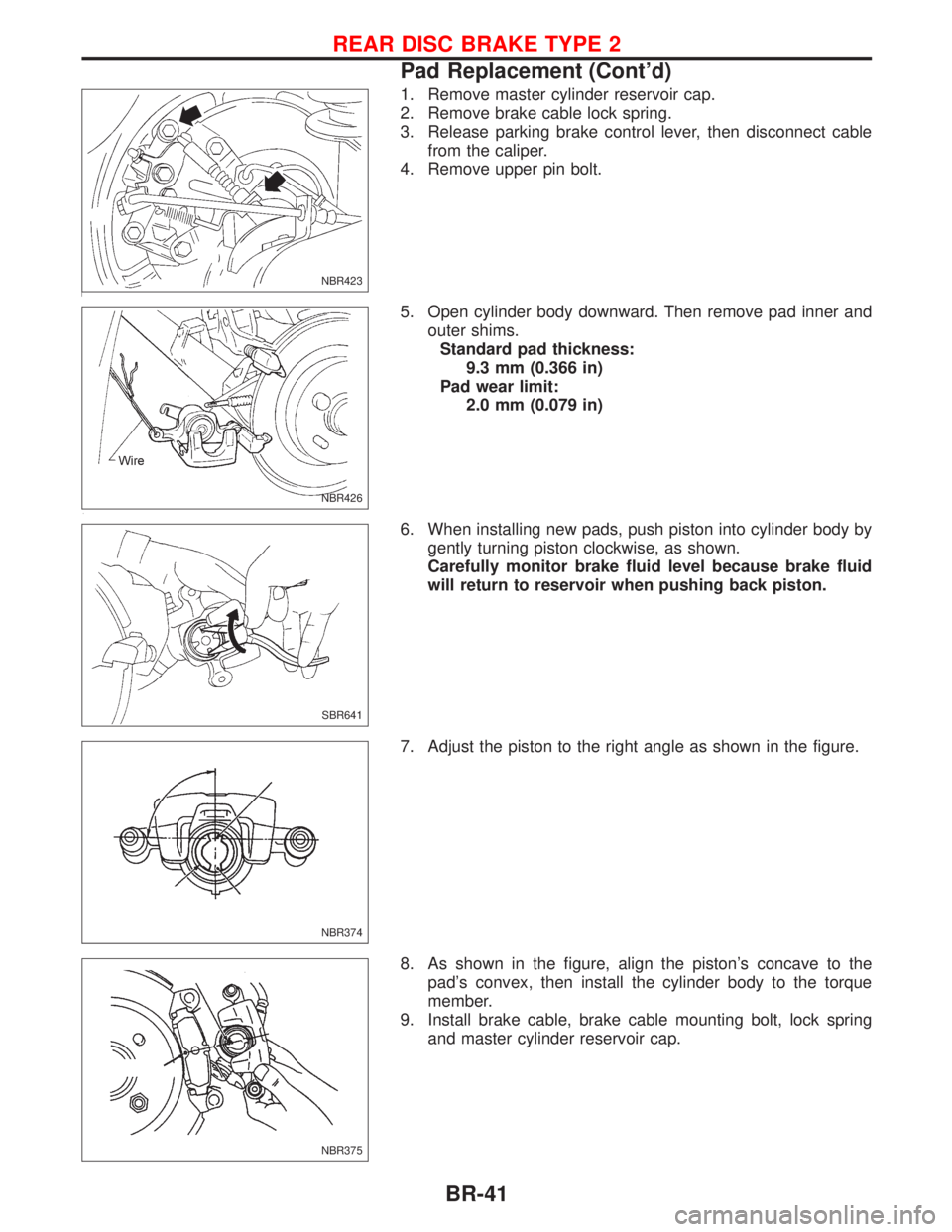
1. Remove master cylinder reservoir cap.
2. Remove brake cable lock spring.
3. Release parking brake control lever, then disconnect cable
from the caliper.
4. Remove upper pin bolt.
5. Open cylinder body downward. Then remove pad inner and
outer shims.
Standard pad thickness:
9.3 mm (0.366 in)
Pad wear limit:
2.0 mm (0.079 in)
6. When installing new pads, push piston into cylinder body by
gently turning piston clockwise, as shown.
Carefully monitor brake fluid level because brake fluid
will return to reservoir when pushing back piston.
7. Adjust the piston to the right angle as shown in the figure.
8. As shown in the figure, align the piston's concave to the
pad's convex, then install the cylinder body to the torque
member.
9. Install brake cable, brake cable mounting bolt, lock spring
and master cylinder reservoir cap.
NBR423
NBR426
SBR641
NBR374
NBR375
REAR DISC BRAKE TYPE 2
Pad Replacement (Cont'd)
BR-41
Page 332 of 2267
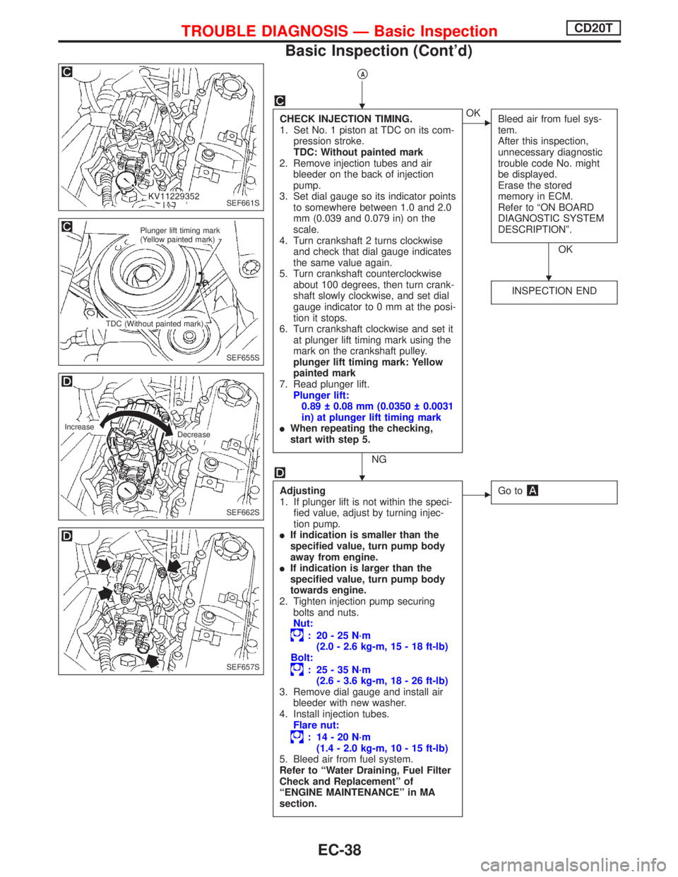
pA
CHECK INJECTION TIMING.
1. Set No. 1 piston at TDC on its com-
pression stroke.
TDC: Without painted mark
2. Remove injection tubes and air
bleeder on the back of injection
pump.
3. Set dial gauge so its indicator points
to somewhere between 1.0 and 2.0
mm (0.039 and 0.079 in) on the
scale.
4. Turn crankshaft 2 turns clockwise
and check that dial gauge indicates
the same value again.
5. Turn crankshaft counterclockwise
about 100 degrees, then turn crank-
shaft slowly clockwise, and set dial
gauge indicator to 0 mm at the posi-
tion it stops.
6. Turn crankshaft clockwise and set it
at plunger lift timing mark using the
mark on the crankshaft pulley.
plunger lift timing mark: Yellow
painted mark
7. Read plunger lift.
Plunger lift:
0.89 0.08 mm (0.0350 0.0031
in) at plunger lift timing mark
lWhen repeating the checking,
start with step 5.
NG
EOK
Bleed air from fuel sys-
tem.
After this inspection,
unnecessary diagnostic
trouble code No. might
be displayed.
Erase the stored
memory in ECM.
Refer to ªON BOARD
DIAGNOSTIC SYSTEM
DESCRIPTIONº.
OK
INSPECTION END
Adjusting
1. If plunger lift is not within the speci-
fied value, adjust by turning injec-
tion pump.
lIf indication is smaller than the
specified value, turn pump body
away from engine.
lIf indication is larger than the
specified value, turn pump body
towards engine.
2. Tighten injection pump securing
bolts and nuts.
Nut:
: 20-25N´m
(2.0 - 2.6 kg-m, 15 - 18 ft-lb)
Bolt:
: 25-35N´m
(2.6 - 3.6 kg-m, 18 - 26 ft-lb)
3. Remove dial gauge and install air
bleeder with new washer.
4. Install injection tubes.
Flare nut:
: 14-20N´m
(1.4 - 2.0 kg-m, 10 - 15 ft-lb)
5. Bleed air from fuel system.
Refer to ªWater Draining, Fuel Filter
Check and Replacementº of
ªENGINE MAINTENANCEº in MA
section.
EGo to
SEF661S
SEF655S
Plunger lift timing mark
(Yellow painted mark)
TDC (Without painted mark)
SEF662S
Increase
Decrease
SEF657S
H
H
H
TROUBLE DIAGNOSIS Ð Basic InspectionCD20T
Basic Inspection (Cont'd)
EC-38
Page 515 of 2267
4 CHECK THROTTLE VALVE OPERATION
1. Remove intake air ducts.
2. Check throttle valve operation when moving throttle drum by hand.
OK or NG
OK©Retighten the throttle drum fixing nuts.
NG©Clean the throttle body and throttle valve.
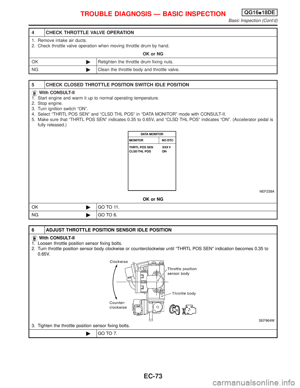
5 CHECK CLOSED THROTTLE POSITION SWITCH IDLE POSITION
With CONSULT-II
1. Start engine and warm it up to normal operating temperature.
2. Stop engine.
3. Turn ignition switch ªONº.
4. Select ªTHRTL POS SENº and ªCLSD THL POSº in ªDATA MONITORº mode with CONSULT-II.
5. Make sure that ªTHRTL POS SENº indicates 0.35 to 0.65V, and ªCLSD THL POSº indicates ªONº. (Accelerator pedal is
fully released.)
NEF238A
OK or NG
OK©GO TO 11.
NG©GO TO 6.
6 ADJUST THROTTLE POSITION SENSOR IDLE POSITION
With CONSULT-II
1. Loosen throttle position sensor fixing bolts.
2. Turn throttle position sensor body clockwise or counterclockwise until ªTHRTL POS SENº indication becomes 0.35 to
0.65V.
SEF964W
3. Tighten the throttle position sensor fixing bolts.
©GO TO 7.
TROUBLE DIAGNOSIS Ð BASIC INSPECTIONQG16I18DE
Basic Inspection (Cont'd)
EC-73
Page 517 of 2267
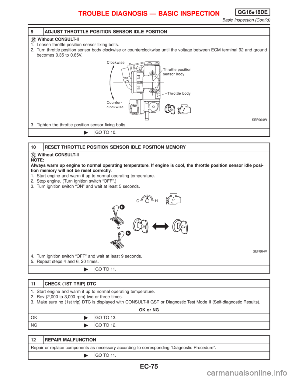
9 ADJUST THROTTLE POSITION SENSOR IDLE POSITION
Without CONSULT-II
1. Loosen throttle position sensor fixing bolts.
2. Turn throttle position sensor body clockwise or counterclockwise until the voltage between ECM terminal 92 and ground
becomes 0.35 to 0.65V.
SEF964W
3. Tighten the throttle position sensor fixing bolts.
©GO TO 10.
10 RESET THROTTLE POSITION SENSOR IDLE POSITION MEMORY
Without CONSULT-II
NOTE:
Always warm up engine to normal operating temperature. If engine is cool, the throttle position sensor idle posi-
tion memory will not be reset correctly.
1. Start engine and warm it up to normal operating temperature.
2. Stop engine. (Turn ignition switch ªOFFº.)
3. Turn ignition switch ªONº and wait at least 5 seconds.
SEF864V
4. Turn ignition switch ªOFFº and wait at least 9 seconds.
5. Repeat steps 4 and 6, 20 times.
©GO TO 11.
11 CHECK (1ST TRIP) DTC
1. Start engine and warm it up to normal operating temperature.
2. Rev (2,000 to 3,000 rpm) two or three times.
3. Make sure no (1st trip) DTC is displayed with CONSULT-II GST or Diagnostic Test Mode II (Self-diagnostic Results).
OK or NG
OK©GO TO 13.
NG©GO TO 12.
12 REPAIR MALFUNCTION
Repair or replace components as necessary according to corresponding ªDiagnostic Procedureº.
©GO TO 11.
TROUBLE DIAGNOSIS Ð BASIC INSPECTIONQG16I18DE
Basic Inspection (Cont'd)
EC-75
Page 885 of 2267
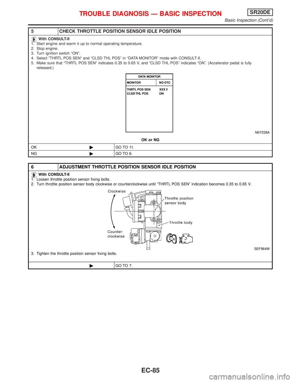
5 CHECK THROTTLE POSITION SENSOR IDLE POSITION
With CONSULT-II
1. Start engine and warm it up to normal operating temperature.
2. Stop engine.
3. Turn ignition switch ªONº.
4. Select ºTHRTL POS SENº and ªCLSD THL POSº in ªDATA MONITORº mode with CONSULT-II.
5. Make sure that ªTHRTL POS SENº indicates 0.35 to 0.65 V, and ªCLSD THL POSº indicates ªONº. (Accelerator pedal is fully
released.)
NEF238A
OK or NG
OK©GO TO 11.
NG©GO TO 6.
6 ADJUSTMENT THROTTLE POSITION SENSOR IDLE POSITION
With CONSULT-II
1. Loosen throttle position sensor fixing bolts.
2. Turn throttle position sensor body clockwise or counterclockwise until ªTHRTL POS SENº indication becomes 0.35 to 0.65 V.
SEF964W3. Tighten the throttle position sensor fixing bolts.
©GO TO 7.
TROUBLE DIAGNOSIS Ð BASIC INSPECTIONSR20DE
Basic Inspection (Cont'd)
EC-85
Page 887 of 2267
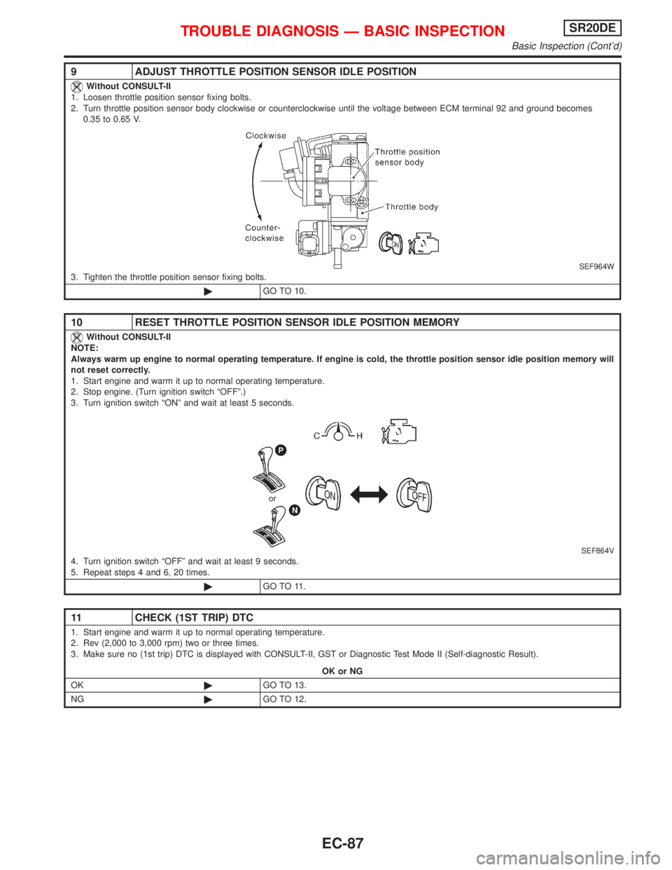
9 ADJUST THROTTLE POSITION SENSOR IDLE POSITION
Without CONSULT-II
1. Loosen throttle position sensor fixing bolts.
2. Turn throttle position sensor body clockwise or counterclockwise until the voltage between ECM terminal 92 and ground becomes
0.35 to 0.65 V.
SEF964W3. Tighten the throttle position sensor fixing bolts.
©GO TO 10.
10 RESET THROTTLE POSITION SENSOR IDLE POSITION MEMORY
Without CONSULT-II
NOTE:
Always warm up engine to normal operating temperature. If engine is cold, the throttle position sensor idle position memory will
not reset correctly.
1. Start engine and warm it up to normal operating temperature.
2. Stop engine. (Turn ignition switch ªOFFº.)
3. Turn ignition switch ªONº and wait at least 5 seconds.
SEF864V4. Turn ignition switch ªOFFº and wait at least 9 seconds.
5. Repeat steps 4 and 6, 20 times.
©GO TO 11.
11 CHECK (1ST TRIP) DTC
1. Start engine and warm it up to normal operating temperature.
2. Rev (2,000 to 3,000 rpm) two or three times.
3. Make sure no (1st trip) DTC is displayed with CONSULT-II, GST or Diagnostic Test Mode II (Self-diagnostic Result).
OK or NG
OK©GO TO 13.
NG©GO TO 12.
TROUBLE DIAGNOSIS Ð BASIC INSPECTIONSR20DE
Basic Inspection (Cont'd)
EC-87
Page 1134 of 2267
HEADLAMP - HEADLAMP AIMING CONTROL
(MANUAL) -................................................................. 87
Wiring Diagram - H/AIM - ........................................ 87
HEADLAMP - HEADLAMP AIMING CONTROL
(AUTO) -....................................................................... 91
System Description .................................................. 91
Initialisation .............................................................. 91
Component Parts and Harness ............................... 92
Wiring Diagram - H/AIM - ........................................ 93
Trouble Diagnosis .................................................... 95
Removal and Installation ......................................... 99
PARKING, LICENSE AND TAIL LAMPS.................. 100
Wiring Diagram - TAIL/L - ...................................... 100
STOP LAMP.............................................................. 104
Wiring Diagram - STOP - ...................................... 104
BACK-UP LAMP........................................................ 107
Wiring Diagram - BACK/L - ................................... 107
FRONT FOG LAMP.................................................... 110
Wiring Diagram - F/FOG - ...................................... 110
Aiming Adjustment .................................................. 111
Bulb Specifications ................................................. 111
REAR FOG LAMP...................................................... 112
Wiring Diagram - R/FOG -...................................... 112
TURN SIGNAL AND HAZARD WARNING LAMPS.. 117
Schematic ............................................................... 117
Wiring Diagram - TURN - ....................................... 118
Trouble Diagnoses................................................. 123
ILLUMINATION.......................................................... 124
Schematic .............................................................. 124
Wiring Diagram - ILL - ........................................... 125
INTERIOR, SPOT, VANITY MIRROR AND
LUGGAGE ROOM LAMPS....................................... 130
System Description ................................................ 130
Schematic .............................................................. 131
Wiring Diagram - INT/L - ....................................... 132
BULB SPECIFICATIONS.......................................... 137
Headlamp............................................................... 137
Exterior Lamp ........................................................ 137
Interior Lamp.......................................................... 137
METER AND GAUGES............................................. 138
System Description ................................................ 138
Combination Meter ................................................ 139
Wiring Diagram - METER -/MODELS BEFORE
VIN - P11U0548750............................................... 141
Schematic .............................................................. 144
Wiring Diagram - METER -/M/T MODELS
AFTER VIN - P11U0548750.................................. 146
Wiring Diagram - METER -/CVT MODELS
AFTER VIN - P11U0548750.................................. 149
Combination Meter Self-Diagnosis ........................ 152
Trouble Diagnoses (Models before VIN -
P11U0548750) ....................................................... 155
Trouble Diagnoses (Models after VIN -
P11U0548750) ....................................................... 159
Fuel Level Sensor Unit Check............................... 164
QG & SR Engine Models ...................................... 164CD20T Engine Models .......................................... 164
Thermal Transmitter Check ................................... 164
WARNING LAMPS.................................................... 165
Warning Lamps/Schematic .................................... 165
Wiring Diagram - WARN - ..................................... 167
Electrical Components Inspection ......................... 179
WARNING CHIME..................................................... 180
System Description ................................................ 180
Wiring Diagram - CHIME - .................................... 181
Trouble Diagnoses................................................. 183
Electrical Components Inspection ......................... 185
FRONT WIPER AND WASHER................................ 186
System Description ................................................ 186
Wiring Diagram - WIPER - .................................... 188
Removal and Installation ....................................... 190
Front Washer Nozzle Adjustment .......................... 192
Front Washer Tube Layout .................................... 192
REAR WIPER AND WASHER.................................. 193
System Description ................................................ 193
Wiring Diagram - WIP/R -...................................... 195
Removal and Installation ....................................... 197
Washer Nozzle Adjustment ................................... 197
Washer Tube Layout ............................................. 199
Check Valve ........................................................... 199
HEADLAMP WASHER.............................................. 200
Wiring Diagram - HLC - ......................................... 200
Washer Tube Layout ............................................. 202
Check Valve ........................................................... 202
HORN, CIGARETTE LIGHTER AND CLOCK.......... 203
Wiring Diagram - HORN - ..................................... 203
REAR WINDOW DEFOGGER AND DOOR
MIRROR DEFOGGER............................................... 207
System Description ................................................ 207
Schematic .............................................................. 208
Wiring Diagram - DEF - ......................................... 209
Trouble Diagnoses................................................. 212
Electrical Components Inspection ......................... 213
Filament Check ...................................................... 213
Filament Repair ..................................................... 214
AUDIO........................................................................ 216
Anti-theft System ................................................... 216
Speed Dependent Volume Control ........................ 217
Personal Audio Settings ........................................ 217
Schematic .............................................................. 218
Wiring Diagram - AUDIO - ..................................... 219
Trouble Diagnoses................................................. 226
Inspection............................................................... 228
AUDIO ANTENNA..................................................... 229
Location of Antenna ............................................... 229
ELECTRIC SUNROOF.............................................. 230
Wiring Diagram - SROOF - ................................... 230
POWER DOOR MIRROR.......................................... 231
Wiring Diagram - MIRROR - ................................. 231
POWER SEAT........................................................... 233
Power Seat/Wiring Diagram - SEAT - ................... 233
HEATED SEAT.......................................................... 234
EL-2