ignition NISSAN PRIMERA 1999 Electronic Repair Manual
[x] Cancel search | Manufacturer: NISSAN, Model Year: 1999, Model line: PRIMERA, Model: NISSAN PRIMERA 1999Pages: 2267, PDF Size: 35.74 MB
Page 7 of 2267
Precautions for Supplemental Restraint System
(SRS) ªAIR BAGº and ªSEAT BELT
PRE-TENSIONERº
NCAT0002The Supplemental Restraint System ªAIR BAGº and ªSEAT BELT PRE-TENSIONERº, used along with a seat
belt, help to reduce the risk or severity of injury to the driver and front passenger in a frontal collision. The
Supplemental Restraint System consists of air bag modules (located in the center of the steering wheel and
on the instrument panel on the passenger side), seat belt pre-tensioners, a diagnosis sensor unit, warning
lamp, wiring harness and spiral cable.
In addition to the supplemental air bag modules for a frontal collision, the supplemental side air bag used along
with the seat belt helps to reduce the risk or severity of injury to the driver and front passenger in a side col-
lision. The supplemental side air bag consists of air bag modules (located in the outer side of front seats),
satellite sensor, diagnosis sensor unit (one of components of supplemental air bags for a frontal collision),
wiring harness, warning lamp (one of components of supplemental air bags for a frontal collision). Information
necessary to service the system safely is included in theRS sectionof this Service Manual.
WARNING:
ITo avoid rendering the SRS inoperative, which could increase the risk of personal injury or death
in the event of a collision which would result in air bag inflation, all maintenance must be performed
by an authorized NISSAN dealer.
IImproper maintenance, including incorrect removal and installation of the SRS, can lead to per-
sonal injury caused by unintentional activation of the system.
IDo not use electrical test equipment on any circuit related to the SRS unless instructed to in this
Service Manual. SRS wiring harnesses (except ªSEAT BELT PRE-TENSIONERº connector) can be
identified with yellow harness connector (and with yellow harness protector or yellow insulation
tape before the harness connectors).
Precautions for On Board Diagnostic (OBD)
System of CVT and Engine
NCAT0198The ECM has an on board diagnostic system. It will light up the malfunction indicator (MI) to warn the driver
of a malfunction causing emission deterioration.
CAUTION:
IBe sure to turn the ignition switch ªOFFº and disconnect the negative battery terminal before any
repair or inspection work. The open/short circuit of related switches, sensors, solenoid valves, etc.
will cause the MI to light up.
IBe sure to connect and lock the connectors securely after work. A loose (unlocked) connector will
cause the MI to light up due to an open circuit. (Be sure the connector is free from water, grease,
dirt, bent terminals, etc.)
IBe sure to route and secure the harnesses properly after work. Interference of the harness with a
bracket, etc. may cause the MI to light up due to a short circuit.
IBe sure to connect rubber tubes properly after work. A misconnected or disconnected rubber tube
may cause the MI to light up due to a malfunction of the EGR system or fuel injection system, etc.
IBe sure to erase the unnecessary malfunction information (repairs completed) from the TCM and
ECM before returning the vehicle to the customer.
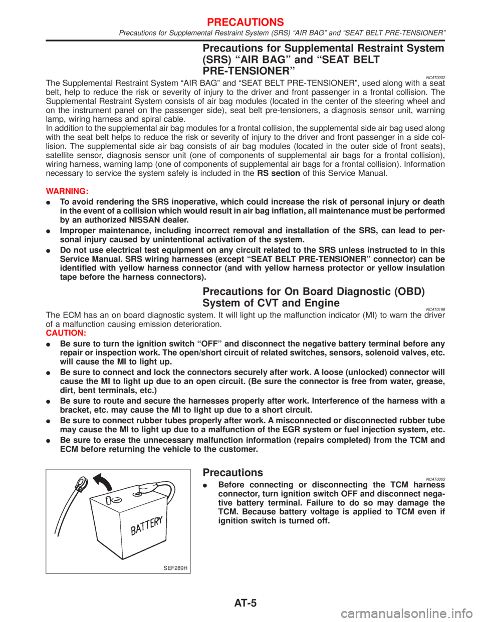
PrecautionsNCAT0003IBefore connecting or disconnecting the TCM harness
connector, turn ignition switch OFF and disconnect nega-
tive battery terminal. Failure to do so may damage the
TCM. Because battery voltage is applied to TCM even if
ignition switch is turned off.
SEF289H
PRECAUTIONS
Precautions for Supplemental Restraint System (SRS) ªAIR BAGº and ªSEAT BELT PRE-TENSIONERº
AT-5
Page 8 of 2267
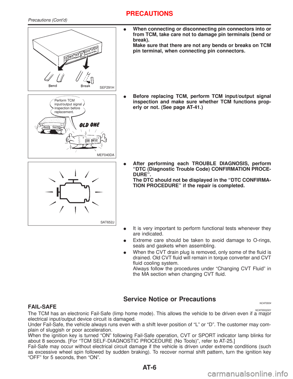
IWhen connecting or disconnecting pin connectors into or
from TCM, take care not to damage pin terminals (bend or
break).
Make sure that there are not any bends or breaks on TCM
pin terminal, when connecting pin connectors.
IBefore replacing TCM, perform TCM input/output signal
inspection and make sure whether TCM functions prop-
erly or not. (See page AT-41.)
IAfter performing each TROUBLE DIAGNOSIS, perform
ªDTC (Diagnostic Trouble Code) CONFIRMATION PROCE-
DUREº.
The DTC should not be displayed in the ªDTC CONFIRMA-
TION PROCEDUREº if the repair is completed.
IIt is very important to perform functional tests whenever they
are indicated.
IExtreme care should be taken to avoid damage to O-rings,
seals and gaskets when assembling.
IWhen the CVT drain plug is removed, only some of the fluid is
drained. Old CVT fluid will remain in torque converter and CVT
fluid cooling system.
Always follow the procedures under ªChanging CVT Fluidº in
the MA section when changing CVT fluid.
Service Notice or PrecautionsNCAT0004FAIL-SAFENCAT0004S01The TCM has an electronic Fail-Safe (limp home mode). This allows the vehicle to be driven even if a major
electrical input/output device circuit is damaged.
Under Fail-Safe, the vehicle always runs even with a shift lever position of ªLº or ªDº. The customer may com-
plain of sluggish or poor acceleration.
When the ignition key is turned ªONº following Fail-Safe operation, CVT or SPORT indicator lamp blinks for
about 8 seconds. [For ªTCM SELF-DIAGNOSTIC PROCEDURE (No Tools)º, refer to AT-25.]
Fail-Safe may occur without electrical circuit damage if the vehicle is driven under extreme conditions (such
as excessive wheel spin followed by sudden braking). To recover normal shift pattern, turn the ignition key
ªOFFº for 5 seconds, then ªONº.
SEF291H
MEF040DA Perform TCM
input/output signal
inspection before
replacement.
SAT652J
PRECAUTIONS
Precautions (Cont'd)
AT-6
Page 19 of 2267
The following emission-related diagnostic information is cleared from the ECM memory when erasing DTC
related to OBD. For details, refer to EC section (ªEmission-related Diagnostic Informationº, ªON BOARD
DIAGNOSTIC SYSTEM DESCRIPTIONº).
IDiagnostic trouble codes (DTC)
I1st trip diagnostic trouble codes (1st trip DTC)
IFreeze frame data
I1st trip freeze frame data
ISystem readiness test (SRT) codes
ITest values
IDistance traveled while MI is activated
IOthers
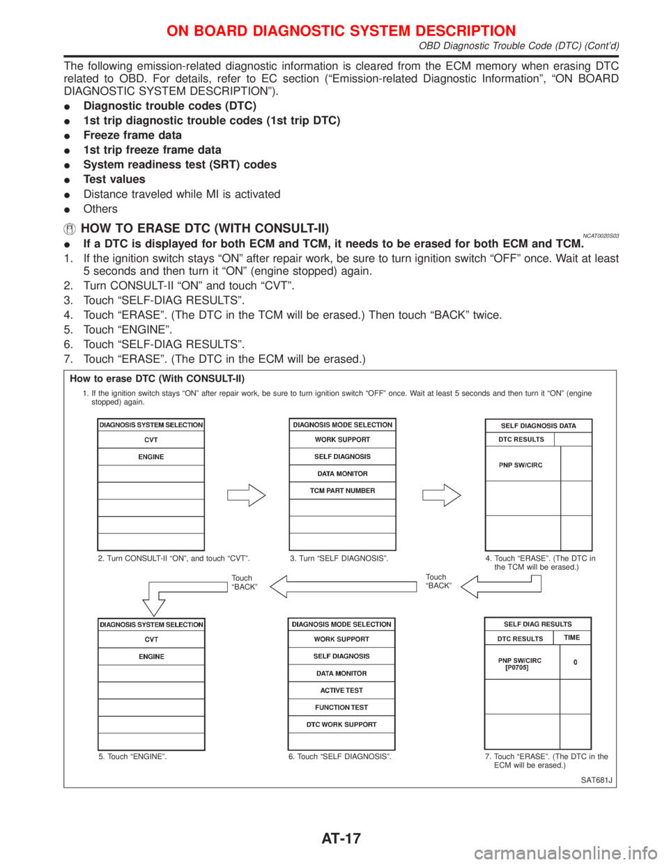
HOW TO ERASE DTC (WITH CONSULT-II)NCAT0020S03IIf a DTC is displayed for both ECM and TCM, it needs to be erased for both ECM and TCM.
1. If the ignition switch stays ªONº after repair work, be sure to turn ignition switch ªOFFº once. Wait at least
5 seconds and then turn it ªONº (engine stopped) again.
2. Turn CONSULT-II ªONº and touch ªCVTº.
3. Touch ªSELF-DIAG RESULTSº.
4. Touch ªERASEº. (The DTC in the TCM will be erased.) Then touch ªBACKº twice.
5. Touch ªENGINEº.
6. Touch ªSELF-DIAG RESULTSº.
7. Touch ªERASEº. (The DTC in the ECM will be erased.)
SAT681J
How to erase DTC (With CONSULT-II)
1. If the ignition switch stays ªONº after repair work, be sure to turn ignition switch ªOFFº once. Wait at least 5 seconds and then turn it ªONº (engine
stopped) again.
2. Turn CONSULT-II ªONº, and touch ªCVTº. 3. Turn ªSELF DIAGNOSISº. 4. Touch ªERASEº. (The DTC in
the TCM will be erased.)
Touch
ªBACKºTouch
ªBACKº
5. Touch ªENGINEº. 6. Touch ªSELF DIAGNOSISº. 7. Touch ªERASEº. (The DTC in the
ECM will be erased.)
.
.
ON BOARD DIAGNOSTIC SYSTEM DESCRIPTION
OBD Diagnostic Trouble Code (DTC) (Cont'd)
AT-17
Page 20 of 2267
HOW TO ERASE DTC (WITH GST)NCAT0020S041. If the ignition switch stays ªONº after repair work, be sure to turn ignition switch ªOFFº once. Wait at least
5 seconds and then turn it ªONº (engine stopped) again.
2. Perform ªOBD SELF-DIAGNOSTIC PROCEDURE (No Tools)º. Refer to AT-25. (The engine warm-up step
can be skipped when performing the diagnosis only to erase the DTC.)
3. Select Mode 4 with Generic Scan Tool (GST). For details, refer to EC section ªGeneric Scan Tool (GST)º.
HOW TO ERASE DTC (NO TOOLS)NCAT0020S051. If the ignition switch stays ªONº after repair work, be sure to turn ignition switch ªOFFº once. Wait at least
5 seconds and then turn it ªONº (engine stopped) again.
2. Perform ªTCM SELF-DIAGNOSTIC PROCEDURE (No Tools)º. Refer to AT-25. (The engine warm-up step
can be skipped when performing the diagnosis only to erase the DTC.)
3. Change the diagnostic test mode from Mode II to Mode I by turning the mode selector on the ECM.
Refer to EC section ªHOW TO SWITCH DIAGNOSTIC TEST MODESº.
Malfunction Indicator (MI)NCAT00211. The malfunction indicator will light up when the ignition switch
is turned ON without the engine running. This is for checking
the lamp.
IIf the malfunction indicator does not light up, refer to EL sec-
tion (ªWarning Lamps/System Descriptionº, ªWARNING
LAMPS AND CHIMEº).
(Or see MI & Data Link Connectors in EC section.)
2. When the engine is started, the malfunction indicator should go
off.
If the lamp remains on, the on board diagnostic system has
detected an emission-related (OBD) malfunction. For detail,
refer to EC section (ªON BOARD DIAGNOSTIC SYSTEM
DESCRIPTIONº).
CONSULT-IINCAT0022After performing ªSELF-DIAGNOSTIC PROCEDURE (WITH CON-
SULT-II)º (AT-19), place check marks for results on the ªDIAGNOS-
TIC WORKSHEETº, AT-31. Reference pages are provided follow-
ing the items.
NOTICE:
IAdditional CONSULT-II information can be found in the Opera-
tion Manual supplied with the CONSULT-II unit.
SAT652J
ON BOARD DIAGNOSTIC SYSTEM DESCRIPTION
OBD Diagnostic Trouble Code (DTC) (Cont'd)
AT-18
Page 26 of 2267
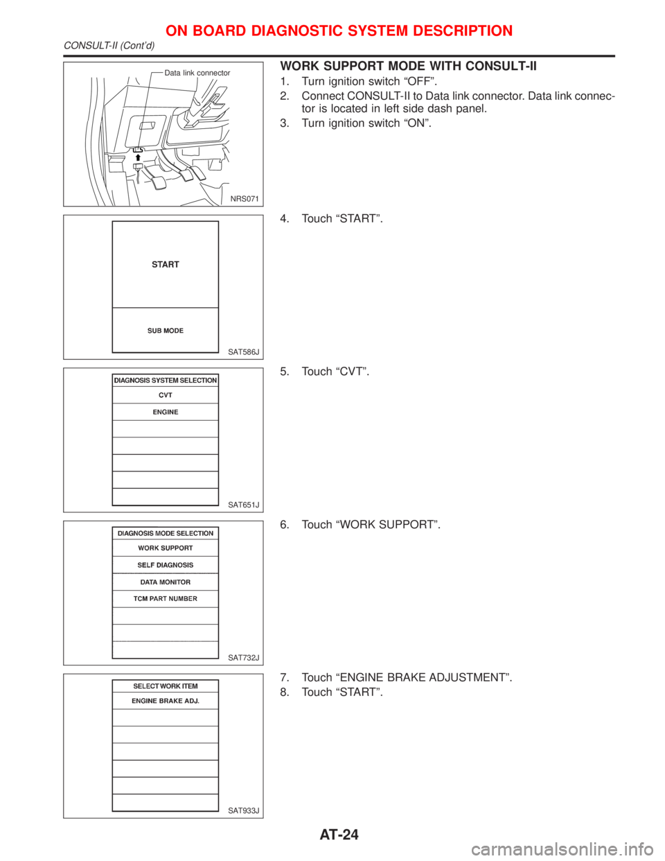
WORK SUPPORT MODE WITH CONSULT-II
1. Turn ignition switch ªOFFº.
2. Connect CONSULT-II to Data link connector. Data link connec-
tor is located in left side dash panel.
3. Turn ignition switch ªONº.
4. Touch ªSTARTº.
5. Touch ªCVTº.
6. Touch ªWORK SUPPORTº.
7. Touch ªENGINE BRAKE ADJUSTMENTº.
8. Touch ªSTARTº.
NRS071 Data link connector
SAT586J
SAT651J
SAT732J
SAT933J
ON BOARD DIAGNOSTIC SYSTEM DESCRIPTION
CONSULT-II (Cont'd)
AT-24
Page 27 of 2267
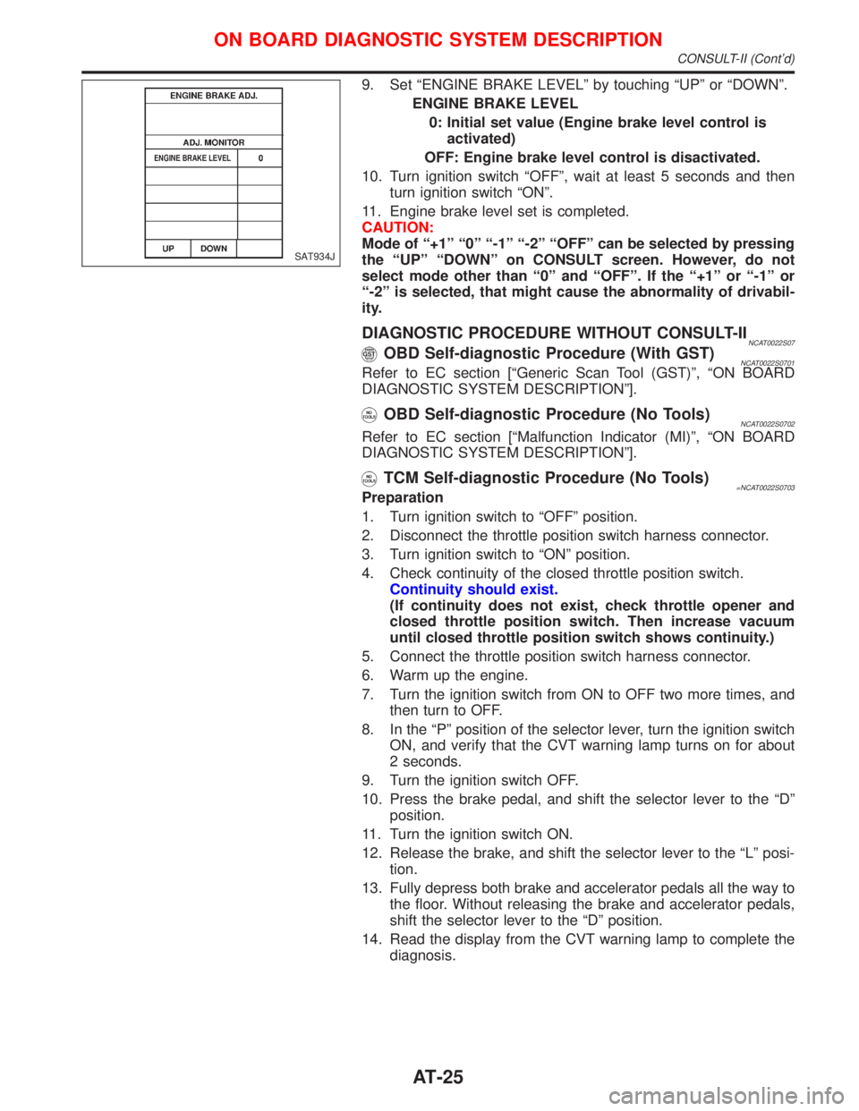
9. Set ªENGINE BRAKE LEVELº by touching ªUPº or ªDOWNº.
ENGINE BRAKE LEVEL
0: Initial set value (Engine brake level control is
activated)
OFF: Engine brake level control is disactivated.
10. Turn ignition switch ªOFFº, wait at least 5 seconds and then
turn ignition switch ªONº.
11. Engine brake level set is completed.
CAUTION:
Mode of ª+1º ª0º ª-1º ª-2º ªOFFº can be selected by pressing
the ªUPº ªDOWNº on CONSULT screen. However, do not
select mode other than ª0º and ªOFFº. If the ª+1º or ª-1º or
ª-2º is selected, that might cause the abnormality of drivabil-
ity.
DIAGNOSTIC PROCEDURE WITHOUT CONSULT-IINCAT0022S07OBD Self-diagnostic Procedure (With GST)NCAT0022S0701Refer to EC section [ªGeneric Scan Tool (GST)º, ªON BOARD
DIAGNOSTIC SYSTEM DESCRIPTIONº].
OBD Self-diagnostic Procedure (No Tools)NCAT0022S0702
Refer to EC section [ªMalfunction Indicator (MI)º, ªON BOARD
DIAGNOSTIC SYSTEM DESCRIPTIONº].
TCM Self-diagnostic Procedure (No Tools)=NCAT0022S0703Preparation
1. Turn ignition switch to ªOFFº position.
2. Disconnect the throttle position switch harness connector.
3. Turn ignition switch to ªONº position.
4. Check continuity of the closed throttle position switch.
Continuity should exist.
(If continuity does not exist, check throttle opener and
closed throttle position switch. Then increase vacuum
until closed throttle position switch shows continuity.)
5. Connect the throttle position switch harness connector.
6. Warm up the engine.
7. Turn the ignition switch from ON to OFF two more times, and
then turn to OFF.
8. In the ªPº position of the selector lever, turn the ignition switch
ON, and verify that the CVT warning lamp turns on for about
2 seconds.
9. Turn the ignition switch OFF.
10. Press the brake pedal, and shift the selector lever to the ªDº
position.
11. Turn the ignition switch ON.
12. Release the brake, and shift the selector lever to the ªLº posi-
tion.
13. Fully depress both brake and accelerator pedals all the way to
the floor. Without releasing the brake and accelerator pedals,
shift the selector lever to the ªDº position.
14. Read the display from the CVT warning lamp to complete the
diagnosis.
SAT934J
ON BOARD DIAGNOSTIC SYSTEM DESCRIPTION
CONSULT-II (Cont'd)
AT-25
Page 39 of 2267
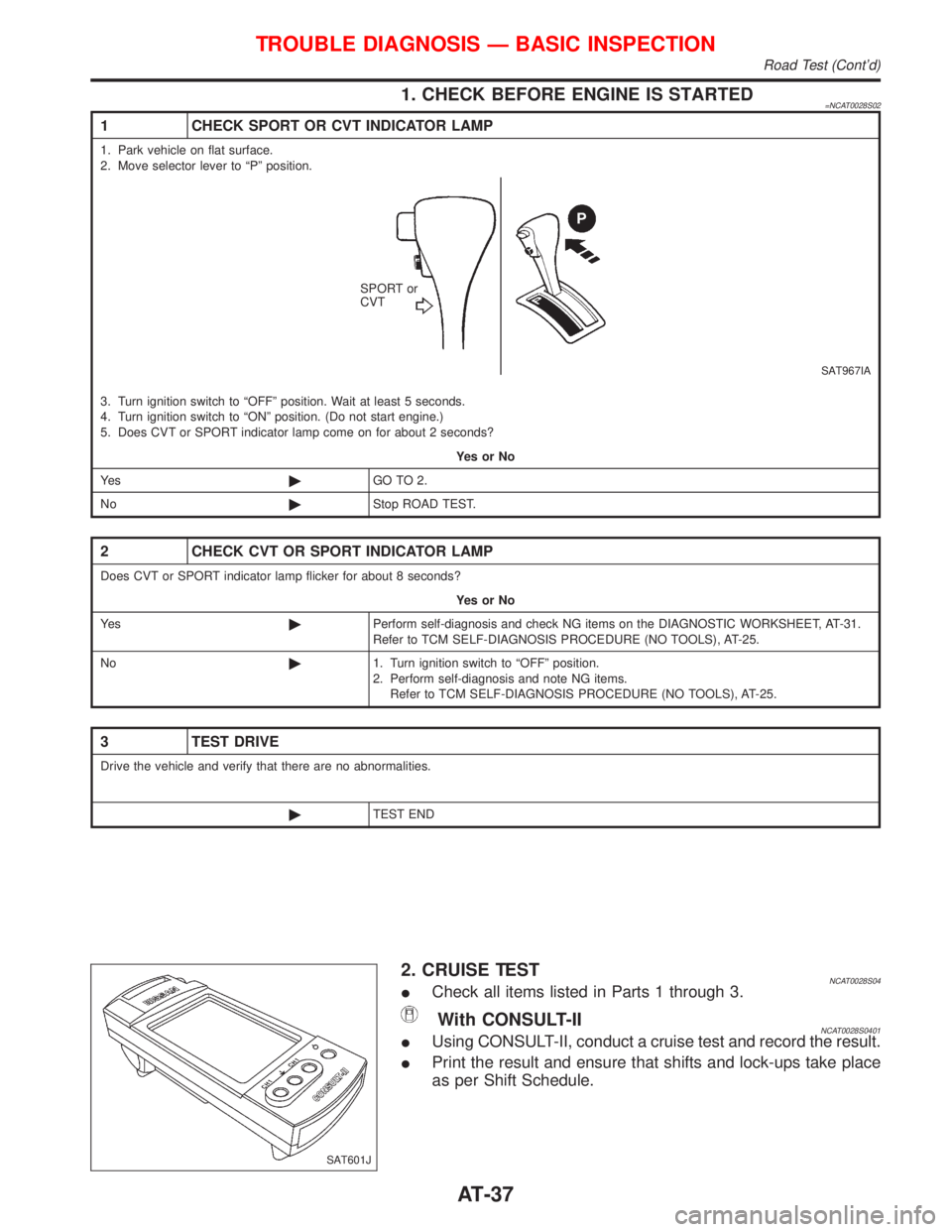
1. CHECK BEFORE ENGINE IS STARTED=NCAT0028S02
1 CHECK SPORT OR CVT INDICATOR LAMP
1. Park vehicle on flat surface.
2. Move selector lever to ªPº position.
SAT967IA
SPORT or
CVT
3. Turn ignition switch to ªOFFº position. Wait at least 5 seconds.
4. Turn ignition switch to ªONº position. (Do not start engine.)
5. Does CVT or SPORT indicator lamp come on for about 2 seconds?
YesorNo
Ye s©GO TO 2.
No©Stop ROAD TEST.
2 CHECK CVT OR SPORT INDICATOR LAMP
Does CVT or SPORT indicator lamp flicker for about 8 seconds?
YesorNo
Ye s©Perform self-diagnosis and check NG items on the DIAGNOSTIC WORKSHEET, AT-31.
Refer to TCM SELF-DIAGNOSIS PROCEDURE (NO TOOLS), AT-25.
No©1. Turn ignition switch to ªOFFº position.
2. Perform self-diagnosis and note NG items.
Refer to TCM SELF-DIAGNOSIS PROCEDURE (NO TOOLS), AT-25.
3 TEST DRIVE
Drive the vehicle and verify that there are no abnormalities.
©TEST END
2. CRUISE TESTNCAT0028S04ICheck all items listed in Parts 1 through 3.
With CONSULT-IINCAT0028S0401IUsing CONSULT-II, conduct a cruise test and record the result.
IPrint the result and ensure that shifts and lock-ups take place
as per Shift Schedule.
SAT601J
TROUBLE DIAGNOSIS Ð BASIC INSPECTION
Road Test (Cont'd)
AT-37
Page 40 of 2267
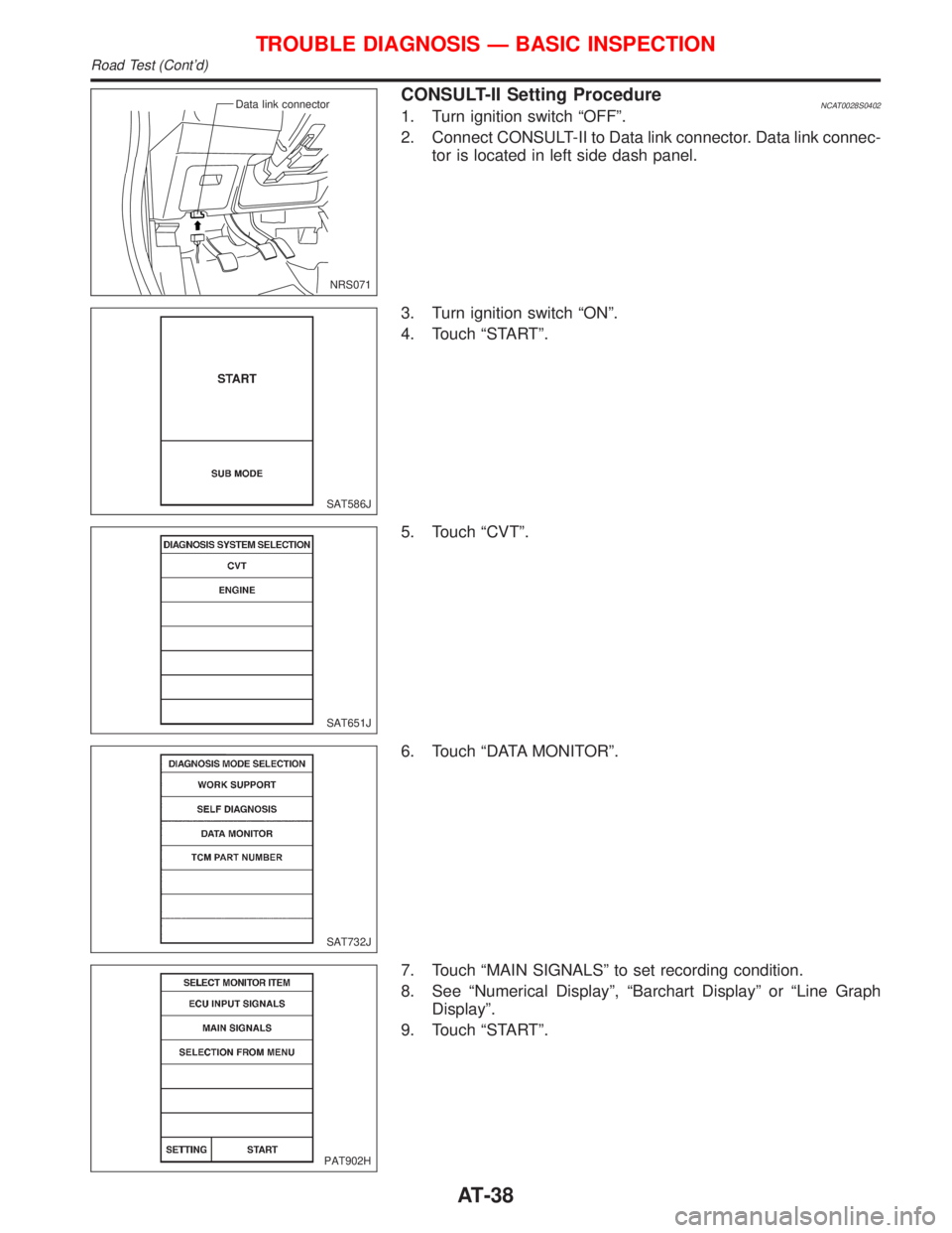
CONSULT-II Setting ProcedureNCAT0028S04021. Turn ignition switch ªOFFº.
2. Connect CONSULT-II to Data link connector. Data link connec-
tor is located in left side dash panel.
3. Turn ignition switch ªONº.
4. Touch ªSTARTº.
5. Touch ªCVTº.
6. Touch ªDATA MONITORº.
7. Touch ªMAIN SIGNALSº to set recording condition.
8. See ªNumerical Displayº, ªBarchart Displayº or ªLine Graph
Displayº.
9. Touch ªSTARTº.
NRS071 Data link connector
SAT586J
SAT651J
SAT732J
PAT902H
TROUBLE DIAGNOSIS Ð BASIC INSPECTION
Road Test (Cont'd)
AT-38
Page 43 of 2267
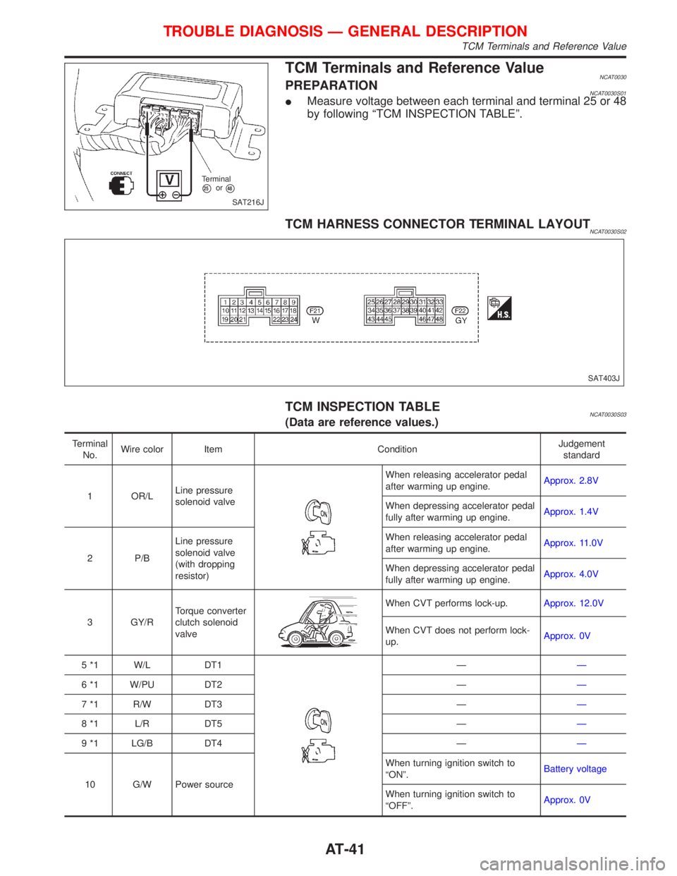
TCM Terminals and Reference ValueNCAT0030PREPARATIONNCAT0030S01IMeasure voltage between each terminal and terminal 25 or 48
by following ªTCM INSPECTION TABLEº.
TCM HARNESS CONNECTOR TERMINAL LAYOUTNCAT0030S02
TCM INSPECTION TABLENCAT0030S03(Data are reference values.)
Terminal
No.Wire color Item ConditionJudgement
standard
1 OR/LLine pressure
solenoid valve
When releasing accelerator pedal
after warming up engine.Approx. 2.8V
When depressing accelerator pedal
fully after warming up engine.Approx. 1.4V
2 P/BLine pressure
solenoid valve
(with dropping
resistor)When releasing accelerator pedal
after warming up engine.Approx. 11.0V
When depressing accelerator pedal
fully after warming up engine.Approx. 4.0V
3 GY/RTorque converter
clutch solenoid
valve
When CVT performs lock-up.Approx. 12.0V
When CVT does not perform lock-
up.Approx. 0V
5 *1 W/L DT1
ÐÐ
6 *1 W/PU DT2 ÐÐ
7 *1 R/W DT3 ÐÐ
8 *1 L/R DT5 ÐÐ
9 *1 LG/B DT4 ÐÐ
10 G/W Power sourceWhen turning ignition switch to
ªONº.Battery voltage
When turning ignition switch to
ªOFFº.Approx. 0V
SAT216J Terminal
p25orp48
SAT403J
TROUBLE DIAGNOSIS Ð GENERAL DESCRIPTION
TCM Terminals and Reference Value
AT-41
Page 45 of 2267
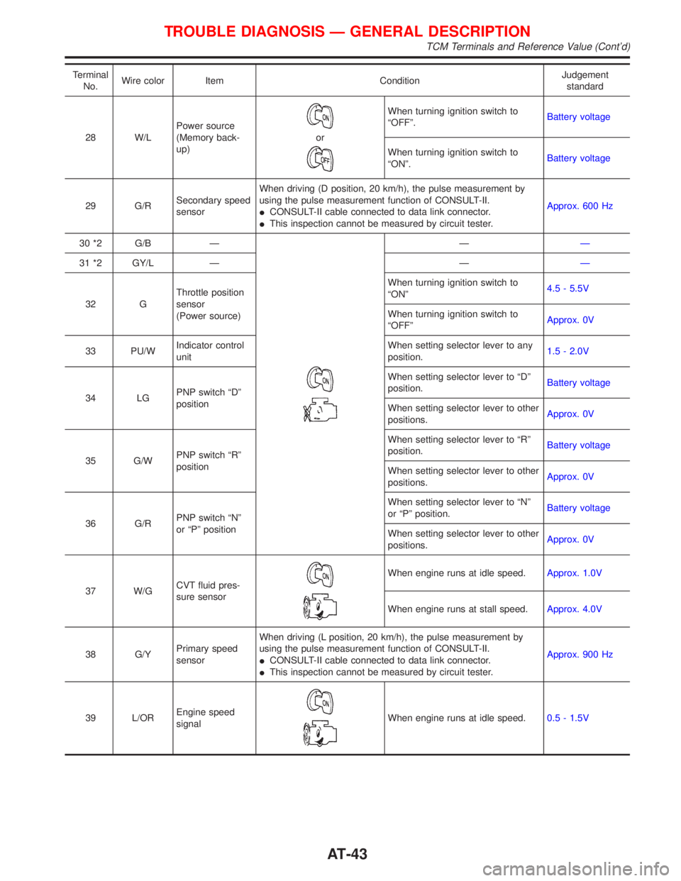
Terminal
No.Wire color Item ConditionJudgement
standard
28 W/LPower source
(Memory back-
up)
or
When turning ignition switch to
ªOFFº.Battery voltage
When turning ignition switch to
ªONº.Battery voltage
29 G/RSecondary speed
sensorWhen driving (D position, 20 km/h), the pulse measurement by
using the pulse measurement function of CONSULT-II.
ICONSULT-II cable connected to data link connector.
IThis inspection cannot be measured by circuit tester.Approx. 600 Hz
30 *2 G/B Ð
ÐÐ
31 *2 GY/L Ð ÐÐ
32 GThrottle position
sensor
(Power source)When turning ignition switch to
ªONº4.5 - 5.5V
When turning ignition switch to
ªOFFºApprox. 0V
33 PU/WIndicator control
unitWhen setting selector lever to any
position.1.5 - 2.0V
34 LGPNP switch ªDº
positionWhen setting selector lever to ªDº
position.Battery voltage
When setting selector lever to other
positions.Approx. 0V
35 G/WPNP switch ªRº
positionWhen setting selector lever to ªRº
position.Battery voltage
When setting selector lever to other
positions.Approx. 0V
36 G/RPNP switch ªNº
or ªPº positionWhen setting selector lever to ªNº
or ªPº position.Battery voltage
When setting selector lever to other
positions.Approx. 0V
37 W/GCVT fluid pres-
sure sensor
When engine runs at idle speed.Approx. 1.0V
When engine runs at stall speed.Approx. 4.0V
38 G/YPrimary speed
sensorWhen driving (L position, 20 km/h), the pulse measurement by
using the pulse measurement function of CONSULT-II.
ICONSULT-II cable connected to data link connector.
IThis inspection cannot be measured by circuit tester.Approx. 900 Hz
39 L/OREngine speed
signal
When engine runs at idle speed.0.5 - 1.5V
TROUBLE DIAGNOSIS Ð GENERAL DESCRIPTION
TCM Terminals and Reference Value (Cont'd)
AT-43