ignition NISSAN PRIMERA 1999 Electronic Repair Manual
[x] Cancel search | Manufacturer: NISSAN, Model Year: 1999, Model line: PRIMERA, Model: NISSAN PRIMERA 1999Pages: 2267, PDF Size: 35.74 MB
Page 2231 of 2267
Trouble Diagnoses without CONSULT-II
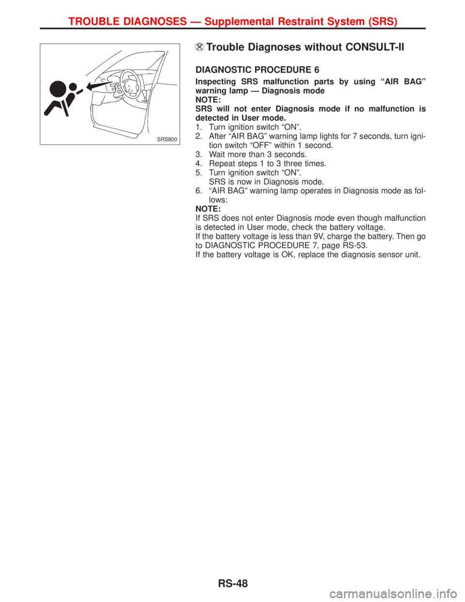
DIAGNOSTIC PROCEDURE 6
Inspecting SRS malfunction parts by using ªAIR BAGº
warning lamp Ð Diagnosis mode
NOTE:
SRS will not enter Diagnosis mode if no malfunction is
detected in User mode.
1. Turn ignition switch ªONº.
2. After ªAIR BAGº warning lamp lights for 7 seconds, turn igni-
tion switch ªOFFº within 1 second.
3. Wait more than 3 seconds.
4. Repeat steps 1 to 3 three times.
5. Turn ignition switch ªONº.
SRS is now in Diagnosis mode.
6. ªAIR BAGº warning lamp operates in Diagnosis mode as fol-
lows:
NOTE:
If SRS does not enter Diagnosis mode even though malfunction
is detected in User mode, check the battery voltage.
If the battery voltage is less than 9V, charge the battery. Then go
to DIAGNOSTIC PROCEDURE 7, page RS-53.
If the battery voltage is OK, replace the diagnosis sensor unit.
SRS800
TROUBLE DIAGNOSES Ð Supplemental Restraint System (SRS)
RS-48
Page 2232 of 2267
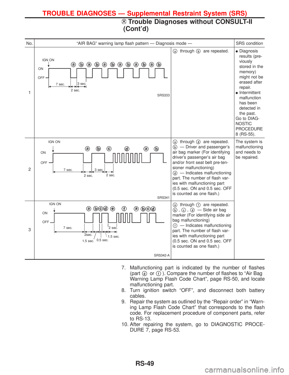
7. Malfunctioning part is indicated by the number of flashes
(part
pdorpf). Compare the number of flashes to ªAir Bag
Warning Lamp Flash Code Chartº, page RS-50, and locate
malfunctioning part.
8. Turn ignition switch ªOFFº, and disconnect both battery
cables.
9. Repair the system as outlined by the ªRepair orderº in ªWarn-
ing Lamp Flash Code Chartº that corresponds to the flash
code. For replacement procedure of component parts, refer
to RS-13.
10. After repairing the system, go to DIAGNOSTIC PROCE-
DURE 7, page RS-53.
No. ªAIR BAGº warning lamp flash pattern Ð Diagnosis mode Ð SRS condition
1
SRS333
pathroughpbare repeated.lDiagnosis
results (pre-
viously
stored in the
memory)
might not be
erased after
repair.
lIntermittent
malfunction
has been
detected in
the past.
Go to DIAG-
NOSTIC
PROCEDURE
8 (RS-55).
2
SRS341
pathroughpdare repeated.
pbÐ Driver and passenger's
air bag marker (For identifying
driver's passenger's air bag
and/or front seat belt pre-ten-
sioner malfunctioning)
pdÐ Indicates malfunctioning
part. The number of flash var-
ies with malfunctioning part
(0.5 sec. ON and 0.5 sec. OFF
is counted as one flash.)The system is
malfunctioning
and needs to
be repaired.
3
SRS342-A
pathroughpfare repeated.
pb,pc,pdÐ Side air bag
marker (For identifying side air
bag malfunctioning)
pfÐ Indicates malfunctioning
part. The number of flash var-
ies with malfunctioning part
(0.5 sec. ON and 0.5 sec. OFF
is counted as one flash.)
IGN ON
ON
OFF
7 sec.3 sec.
2 sec.
IGN ON
ON
OFF
7 sec.3 sec.
2 sec.2 sec.
0.5 sec.
1.5 sec. IGN ON
ON
OFF
7 sec.
2sec.
1.5 sec.2 sec.
TROUBLE DIAGNOSES Ð Supplemental Restraint System (SRS)
Trouble Diagnoses without CONSULT-II
(Cont'd)
RS-49
Page 2236 of 2267
DIAGNOSTIC PROCEDURE 7
Final checking after repairing SRS by using ªAIR BAGº
warning lamp Ð Diagnosis mode and User mode
1. After repairing SRS connect both battery cables.
2. Turn ignition switch from ªOFFº to ªONº.
3. ªAIR BAGº warning lamp operates in Diagnosis mode as fol-
lows:
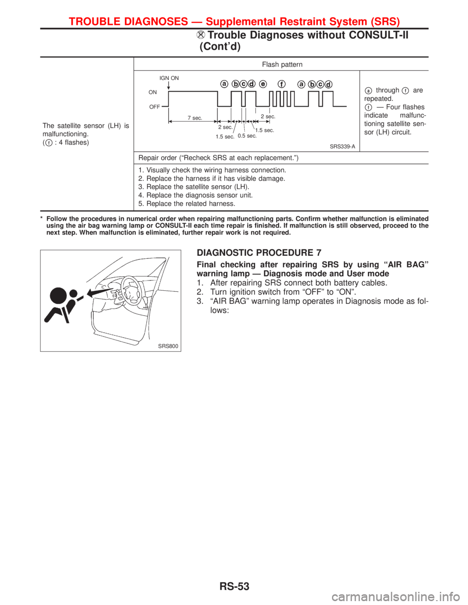
The satellite sensor (LH) is
malfunctioning.
(
pf: 4 flashes)Flash patternSRS339-A
pathroughpfare
repeated.
pfÐ Four flashes
indicate malfunc-
tioning satellite sen-
sor (LH) circuit.
Repair order (ªRecheck SRS at each replacement.º)
1. Visually check the wiring harness connection.
2. Replace the harness if it has visible damage.
3. Replace the satellite sensor (LH).
4. Replace the diagnosis sensor unit.
5. Replace the related harness.
* Follow the procedures in numerical order when repairing malfunctioning parts. Confirm whether malfunction is eliminated
using the air bag warning lamp or CONSULT-II each time repair is finished. If malfunction is still observed, proceed to the
next step. When malfunction is eliminated, further repair work is not required.
IGN ON
ON
OFF
7 sec.2 sec.
2 sec.
1.5 sec.
1.5 sec.0.5 sec.
SRS800
TROUBLE DIAGNOSES Ð Supplemental Restraint System (SRS)
Trouble Diagnoses without CONSULT-II
(Cont'd)
RS-53
Page 2237 of 2267
NOTE:
When diagnosis sensor unit is replaced with a new one,
ªAIR BAGº warning lamp will operate in User mode. Check-
ing ªAIR BAGº warning lamp operation in Diagnosis mode
is not required. Go to step 6.
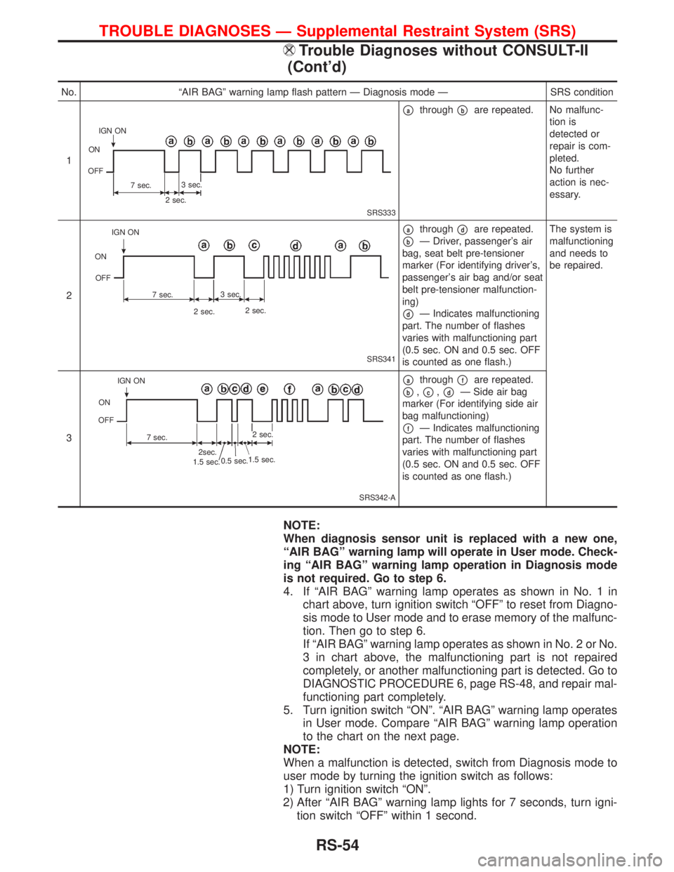
4. If ªAIR BAGº warning lamp operates as shown in No. 1 in
chart above, turn ignition switch ªOFFº to reset from Diagno-
sis mode to User mode and to erase memory of the malfunc-
tion. Then go to step 6.
If ªAIR BAGº warning lamp operates as shown in No. 2 or No.
3 in chart above, the malfunctioning part is not repaired
completely, or another malfunctioning part is detected. Go to
DIAGNOSTIC PROCEDURE 6, page RS-48, and repair mal-
functioning part completely.
5. Turn ignition switch ªONº. ªAIR BAGº warning lamp operates
in User mode. Compare ªAIR BAGº warning lamp operation
to the chart on the next page.
NOTE:
When a malfunction is detected, switch from Diagnosis mode to
user mode by turning the ignition switch as follows:
1) Turn ignition switch ªONº.
2) After ªAIR BAGº warning lamp lights for 7 seconds, turn igni-
tion switch ªOFFº within 1 second.
No. ªAIR BAGº warning lamp flash pattern Ð Diagnosis mode Ð SRS condition
1
SRS333
pathroughpbare repeated. No malfunc-
tion is
detected or
repair is com-
pleted.
No further
action is nec-
essary.
2
SRS341
pathroughpdare repeated.
pbÐ Driver, passenger's air
bag, seat belt pre-tensioner
marker (For identifying driver's,
passenger's air bag and/or seat
belt pre-tensioner malfunction-
ing)
pdÐ Indicates malfunctioning
part. The number of flashes
varies with malfunctioning part
(0.5 sec. ON and 0.5 sec. OFF
is counted as one flash.)The system is
malfunctioning
and needs to
be repaired.
3
SRS342-A
pathroughpfare repeated.
pb,pc,pdÐ Side air bag
marker (For identifying side air
bag malfunctioning)
pfÐ Indicates malfunctioning
part. The number of flashes
varies with malfunctioning part
(0.5 sec. ON and 0.5 sec. OFF
is counted as one flash.)
IGN ON
ON
OFF
7 sec.3 sec.
2 sec.
IGN ON
ON
OFF
7 sec.3 sec.
2 sec.2 sec.
0.5 sec.
1.5 sec. IGN ON
ON
OFF
7 sec.
2sec.
1.5 sec.2 sec.
TROUBLE DIAGNOSES Ð Supplemental Restraint System (SRS)
Trouble Diagnoses without CONSULT-II
(Cont'd)
RS-54
Page 2238 of 2267
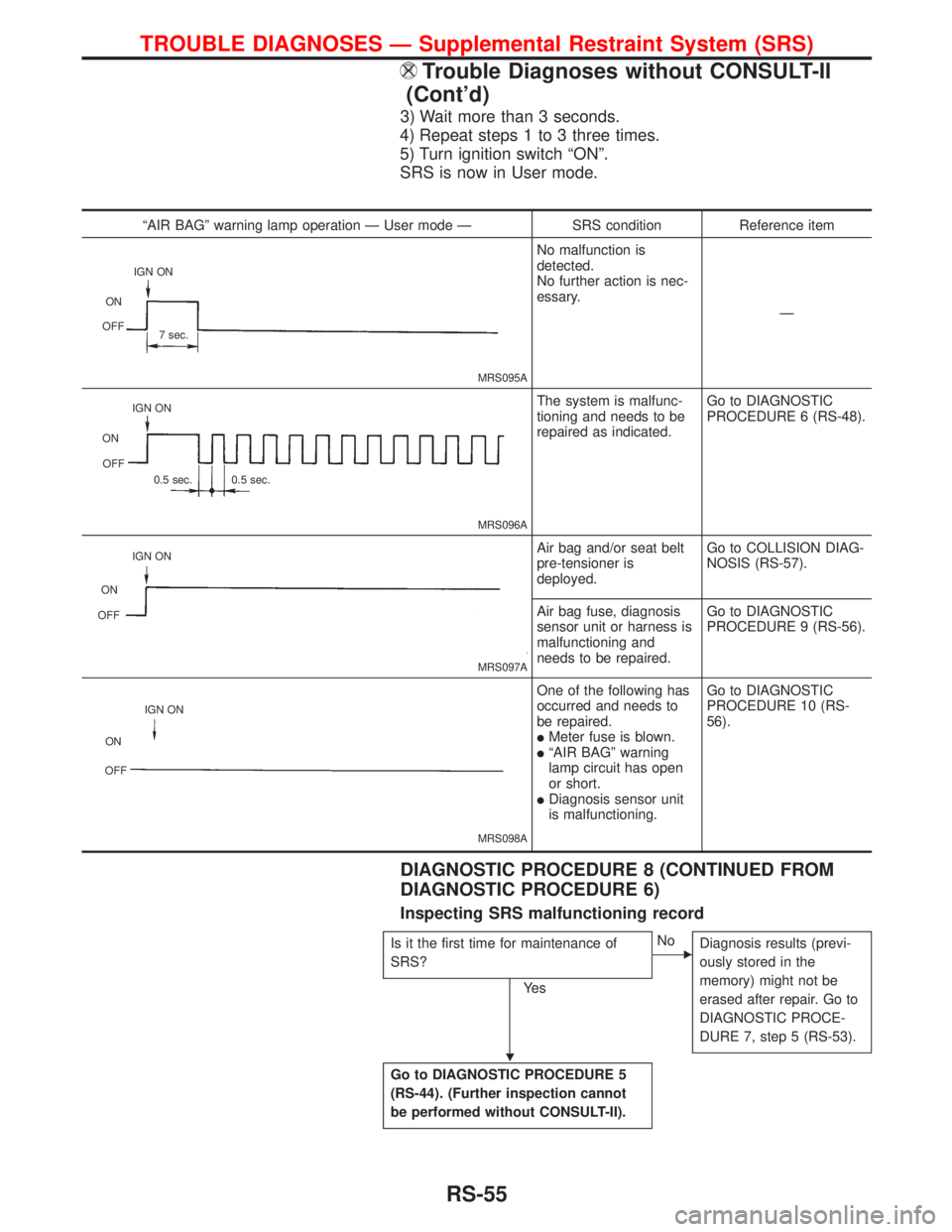
3) Wait more than 3 seconds.
4) Repeat steps 1 to 3 three times.
5) Turn ignition switch ªONº.
SRS is now in User mode.
DIAGNOSTIC PROCEDURE 8 (CONTINUED FROM
DIAGNOSTIC PROCEDURE 6)
Inspecting SRS malfunctioning record
Is it the first time for maintenance of
SRS?
Ye s
ENo
Diagnosis results (previ-
ously stored in the
memory) might not be
erased after repair. Go to
DIAGNOSTIC PROCE-
DURE 7, step 5 (RS-53).
Go to DIAGNOSTIC PROCEDURE 5
(RS-44). (Further inspection cannot
be performed without CONSULT-II).
ªAIR BAGº warning lamp operation Ð User mode Ð SRS condition Reference item
MRS095A
No malfunction is
detected.
No further action is nec-
essary.
Ð
MRS096A
The system is malfunc-
tioning and needs to be
repaired as indicated.Go to DIAGNOSTIC
PROCEDURE 6 (RS-48).
MRS097A
Air bag and/or seat belt
pre-tensioner is
deployed.Go to COLLISION DIAG-
NOSIS (RS-57).
Air bag fuse, diagnosis
sensor unit or harness is
malfunctioning and
needs to be repaired.Go to DIAGNOSTIC
PROCEDURE 9 (RS-56).
MRS098A
One of the following has
occurred and needs to
be repaired.
lMeter fuse is blown.lªAIR BAGº warning
lamp circuit has open
or short.
lDiagnosis sensor unit
is malfunctioning.Go to DIAGNOSTIC
PROCEDURE 10 (RS-
56).
IGN ON
ON
OFF
7 sec.
IGN ON
ON
OFF
0.5 sec. 0.5 sec.
IGN ON
ON
OFF
IGN ON
ON
OFF
H
TROUBLE DIAGNOSES Ð Supplemental Restraint System (SRS)
Trouble Diagnoses without CONSULT-II
(Cont'd)
RS-55
Page 2239 of 2267
Trouble Diagnoses for Air Bag Warning Lamp
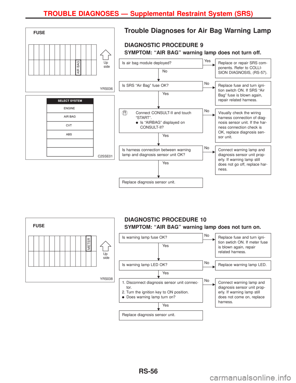
DIAGNOSTIC PROCEDURE 9
SYMPTOM: ªAIR BAGº warning lamp does not turn off.
Is air bag module deployed?
No
EYe s
Replace or repair SRS com-
ponents. Refer to COLLI-
SION DIAGNOSIS, (RS-57).
Is SRS ªAir Bagº fuse OK?
Ye s
ENo
Replace fuse and turn igni-
tion switch ON. If SRS ªAir
Bagº fuse is blown again,
repair related harness.
Connect CONSULT-II and touch
ªSTARTº.
lIs ªAIRBAGº displayed on
CONSULT-II?
Ye s
ENo
Visually check the wiring
harness connection of diag-
nosis sensor unit. If the har-
ness connection check is
OK, replace diagnosis sen-
sor unit.
Is harness connection between warning
lamp and diagnosis sensor unit OK?
Ye s
ENo
Connect warning lamp and
diagnosis sensor unit prop-
erly. If warning lamp still
does not go off, replace har-
ness.
Replace diagnosis sensor unit.
DIAGNOSTIC PROCEDURE 10
SYMPTOM: ªAIR BAGº warning lamp does not turn on.
Is warning lamp fuse OK?
Ye s
ENo
Replace fuse and turn igni-
tion swtich ON. If meter fuse
is blown again, repair
related harness.
Is warning lamp LED OK?
Ye s
ENo
Replace warning lamp LED.
1. Disconnect diagnosis sensor unit connec-
tor.
2. Turn the ignition key to ON position.
lDoes warning lamp turn on?
Ye s
ENo
Connect warning lamp and
diagnosis sensor unit prop-
erly. If warning lamp still
does not come on, replace
harness.
Replace diagnosis sensor unit.
YRS036
FUSE
Up
side
AIR BAG
C2SSE01
YRS038
FUSE
Up
side
METER
H
H
H
H
H
H
H
TROUBLE DIAGNOSES Ð Supplemental Restraint System (SRS)
RS-56
Page 2248 of 2267
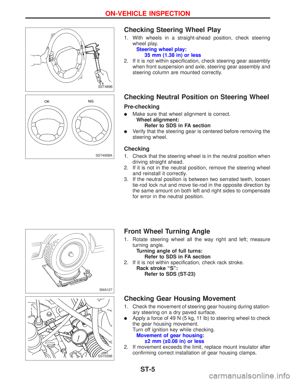
Checking Steering Wheel Play
1. With wheels in a straight-ahead position, check steering
wheel play.
Steering wheel play:
35 mm (1.38 in) or less
2. If it is not within specification, check steering gear assembly
when front suspension and axle, steering gear assembly and
steering column are mounted correctly.
Checking Neutral Position on Steering Wheel
Pre-checking
lMake sure that wheel alignment is correct.
Wheel alignment:
Refer to SDS in FA section
lVerify that the steering gear is centered before removing the
steering wheel.
Checking
1. Check that the steering wheel is in the neutral position when
driving straight ahead.
2. If it is not in the neutral position, remove the steering wheel
and reinstall it correctly.
3. If the neutral position is between two serrated teeth, loosen
tie-rod lock nut and move tie-rod in the opposite direction by
the same amount on both left and right sides to compensate
for error in the neutral position.
Front Wheel Turning Angle
1. Rotate steering wheel all the way right and left; measure
turning angle.
Turning angle of full turns:
Refer to SDS in FA section
2. If it is not within specification, check rack stroke.
Rack stroke ªSº:
Refer to SDS (ST-23)
Checking Gear Housing Movement
1. Check the movement of steering gear housing during station-
ary steering on a dry paved surface.
lApply a force of 49 N (5 kg, 11 lb) to steering wheel to check
the gear housing movement.
Turn off ignition key while checking.
Movement of gear housing:
2 mm ( 0.08 in) or less
2. If movement exceeds the limit, replace mount insulator after
confirming correct installation of gear housing clamps.
.SST489B
SST490BA
SMA127
.SST059B
ON-VEHICLE INSPECTION
ST-5
Page 2252 of 2267
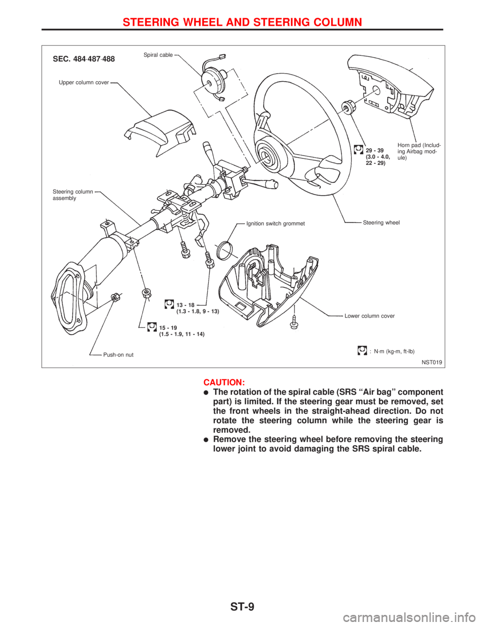
CAUTION:
lThe rotation of the spiral cable (SRS ªAir bagº component
part) is limited. If the steering gear must be removed, set
the front wheels in the straight-ahead direction. Do not
rotate the steering column while the steering gear is
removed.
lRemove the steering wheel before removing the steering
lower joint to avoid damaging the SRS spiral cable.
NST019 Upper column cover
Steering column
assembly
Ignition switch grommet
Lower column cover
13-18
(1.3 - 1.8, 9 - 13)
15-19
(1.5 - 1.9, 11 - 14)
Push-on nut
: N´m (kg-m, ft-lb)
SEC. 484×487×488Spiral cable
Steering wheel
29-39
(3.0 - 4.0,
22 - 29)Horn pad (Includ-
ing Airbag mod-
ule)
STEERING WHEEL AND STEERING COLUMN
ST-9