sr20 NISSAN PRIMERA 1999 Electronic Repair Manual
[x] Cancel search | Manufacturer: NISSAN, Model Year: 1999, Model line: PRIMERA, Model: NISSAN PRIMERA 1999Pages: 2267, PDF Size: 35.74 MB
Page 1 of 2267
Edition:May 2001
GENERA LINFORMATIONGI
MAINTENANCEMA
ENGIN EMECHANICALEM
ENGIN ELUBRICATIO N&LC
ENGIN ECONTRO LSYSTEMQG16/18DE
ENGIN ECONTRO LSYSTEMSR20DE
ENGIN ECONTRO LSYSTEMCD20T
ACCELERATO RCONTROL,FE
CLUTCHCL
MANUA LTRANSAXLEMT
AUTOMATI CTRANSAXLEAT
FRON TAXL E& FRON TSUSPENSIONFA
REA RAXL E& REA RSUSPENSIONRA
BRAK ESYSTEMBR
STEERIN GSYSTEMST
RESTRAIN TSYSTEMRS
BOD Y& TRIMBT
HEATE R&AIR CONDITIONERHA
ELECTRICA LSYSTEMEL
ALPHABETICA LINDEXIDX
PRIMERA
NISSA NEUROP EN.V.
Page 120 of 2267
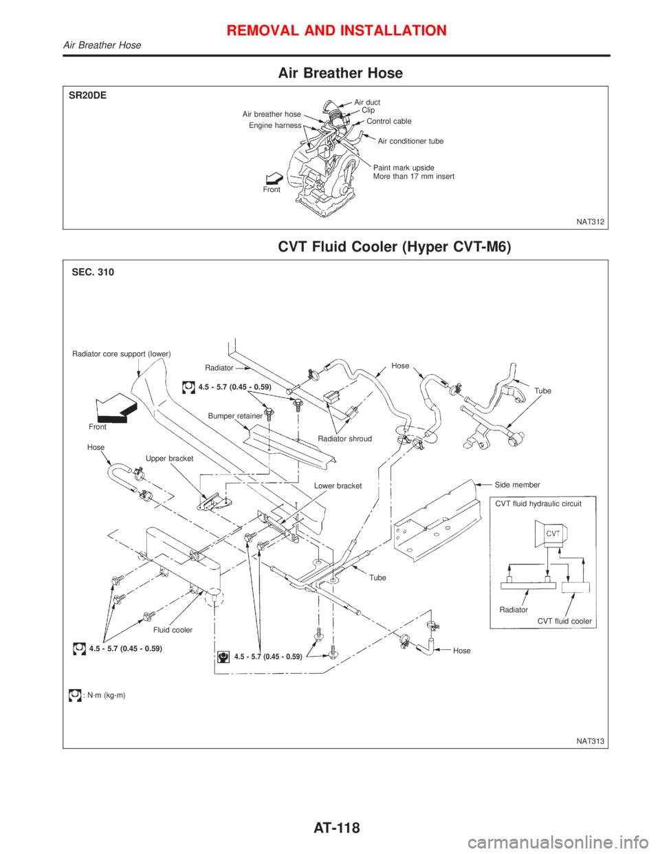
Air Breather Hose
CVT Fluid Cooler (Hyper CVT-M6)
Air duct
Clip
Control cable
Air conditioner tube
Paint mark upside
More than 17 mm insert
Front Engine harness Air breather hose
NAT312
SR20DE
Radiator core support (lower)
Radiator
4.5 - 5.7 (0.45 - 0.59)
Bumper retainer
Front
Hose
Upper bracket
Fluid cooler
4.5 - 5.7 (0.45 - 0.59)
: N´m (kg-m)
4.5 - 5.7 (0.45 - 0.59)
Tube
HoseRadiator
CVT fluid cooler CVT fluid hydraulic circuit Side memberTube Hose
Radiator shroud
Lower bracket
NAT313
SEC. 310
REMOVAL AND INSTALLATION
Air Breather Hose
AT-118
Page 122 of 2267
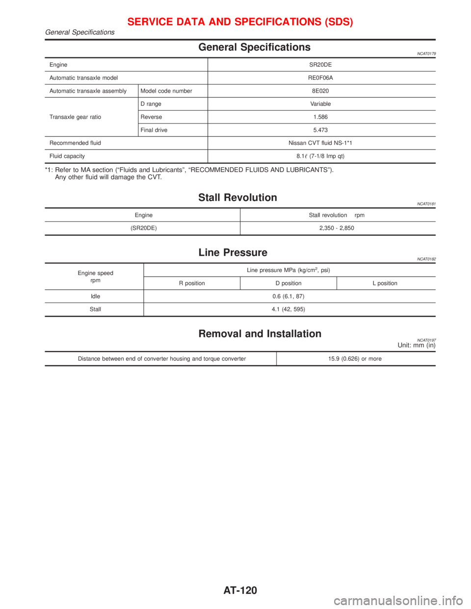
General SpecificationsNCAT0179
EngineSR20DE
Automatic transaxle modelRE0F06A
Automatic transaxle assembly Model code number 8E020
Transaxle gear ratioD range Variable
Reverse 1.586
Final drive 5.473
Recommended fluidNissan CVT fluid NS-1*1
Fluid capacity8.1(7-1/8 Imp qt)
*1: Refer to MA section (ªFluids and Lubricantsº, ªRECOMMENDED FLUIDS AND LUBRICANTSº).
Any other fluid will damage the CVT.
Stall RevolutionNCAT0181
Engine Stall revolution rpm
(SR20DE) 2,350 - 2,850
Line PressureNCAT0182
Engine speed
rpmLine pressure MPa (kg/cm2, psi)
R position D position L position
Idle 0.6 (6.1, 87)
Stall 4.1 (42, 595)
Removal and InstallationNCAT0197Unit: mm (in)
Distance between end of converter housing and torque converter 15.9 (0.626) or more
SERVICE DATA AND SPECIFICATIONS (SDS)
General Specifications
AT-120
Page 123 of 2267
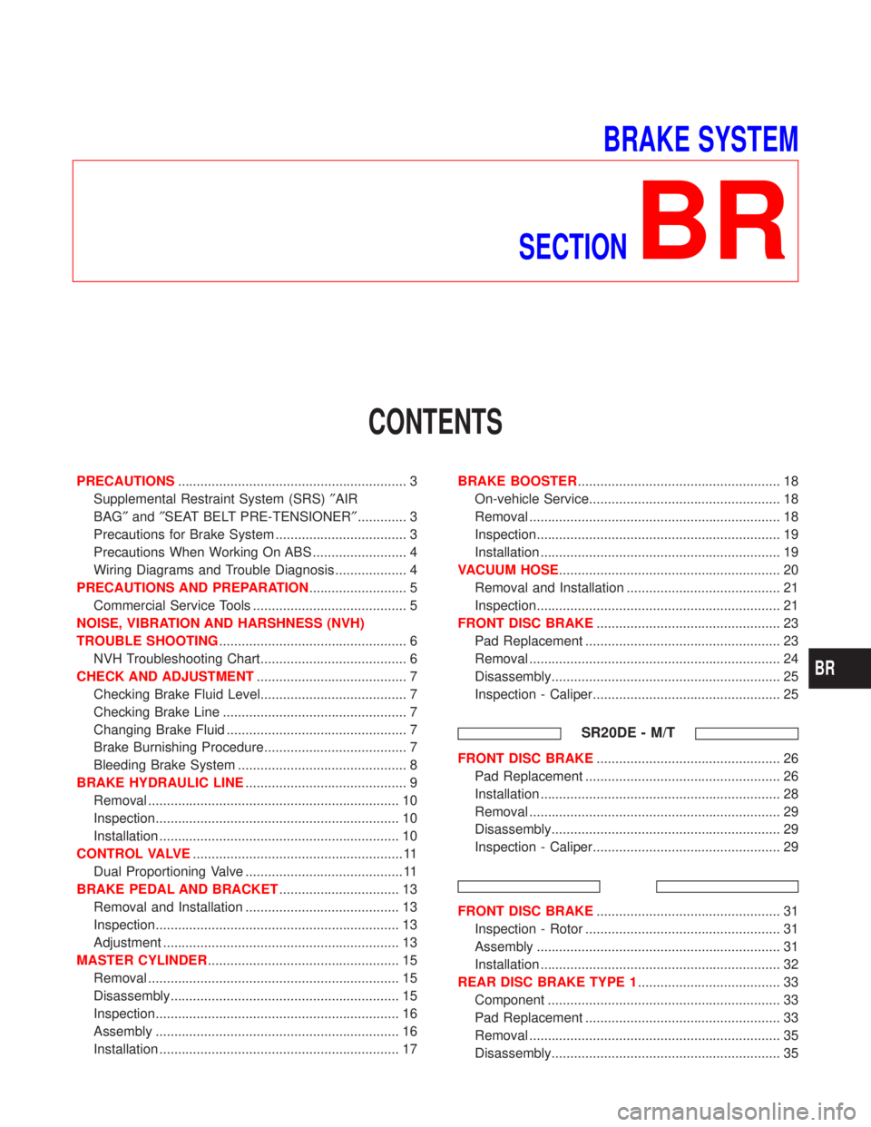
BRAKE SYSTEM
SECTION
BR
CONTENTS
PRECAUTIONS............................................................. 3
Supplemental Restraint System (SRS)²AIR
BAG²and²SEAT BELT PRE-TENSIONER²............. 3
Precautions for Brake System ................................... 3
Precautions When Working On ABS ......................... 4
Wiring Diagrams and Trouble Diagnosis ................... 4
PRECAUTIONS AND PREPARATION.......................... 5
Commercial Service Tools ......................................... 5
NOISE, VIBRATION AND HARSHNESS (NVH)
TROUBLE SHOOTING.................................................. 6
NVH Troubleshooting Chart....................................... 6
CHECK AND ADJUSTMENT........................................ 7
Checking Brake Fluid Level....................................... 7
Checking Brake Line ................................................. 7
Changing Brake Fluid ................................................ 7
Brake Burnishing Procedure...................................... 7
Bleeding Brake System ............................................. 8
BRAKE HYDRAULIC LINE........................................... 9
Removal ................................................................... 10
Inspection................................................................. 10
Installation ................................................................ 10
CONTROL VALVE........................................................ 11
Dual Proportioning Valve .......................................... 11
BRAKE PEDAL AND BRACKET................................ 13
Removal and Installation ......................................... 13
Inspection................................................................. 13
Adjustment ............................................................... 13
MASTER CYLINDER................................................... 15
Removal ................................................................... 15
Disassembly............................................................. 15
Inspection................................................................. 16
Assembly ................................................................. 16
Installation ................................................................ 17BRAKE BOOSTER...................................................... 18
On-vehicle Service................................................... 18
Removal ................................................................... 18
Inspection................................................................. 19
Installation ................................................................ 19
VACUUM HOSE........................................................... 20
Removal and Installation ......................................... 21
Inspection................................................................. 21
FRONT DISC BRAKE................................................. 23
Pad Replacement .................................................... 23
Removal ................................................................... 24
Disassembly............................................................. 25
Inspection - Caliper.................................................. 25
SR20DE - M/T
FRONT DISC BRAKE................................................. 26
Pad Replacement .................................................... 26
Installation ................................................................ 28
Removal ................................................................... 29
Disassembly............................................................. 29
Inspection - Caliper.................................................. 29
FRONT DISC BRAKE................................................. 31
Inspection - Rotor .................................................... 31
Assembly ................................................................. 31
Installation ................................................................ 32
REAR DISC BRAKE TYPE 1...................................... 33
Component .............................................................. 33
Pad Replacement .................................................... 33
Removal ................................................................... 35
Disassembly............................................................. 35
BR
Page 148 of 2267
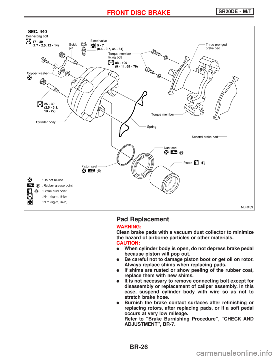
Pad Replacement
WARNING:
Clean brake pads with a vacuum dust collector to minimize
the hazard of airborne particles or other materials.
CAUTION:
lWhen cylinder body is open, do not depress brake pedal
because piston will pop out.
lBe careful not to damage piston boot or get oil on rotor.
Always replace shims when replacing pads.
lIf shims are rusted or show peeling of the rubber coat,
replace them with new shims.
lIt is not necessary to remove connecting bolt except for
disassembly or replacement of caliper assembly. In this
case, suspend cylinder body with wire so as not to
stretch brake hose.
lBurnish the brake contact surfaces after refinishing or
replacing rotors, after replacing pads, or if a soft pedal
occurs at very low mileage.
Refer to ªBrake Burnishing Procedureº, ªCHECK AND
ADJUSTMENTº, BR-7.
NBR439
FRONT DISC BRAKESR20DE - M/T
BR-26
Page 149 of 2267
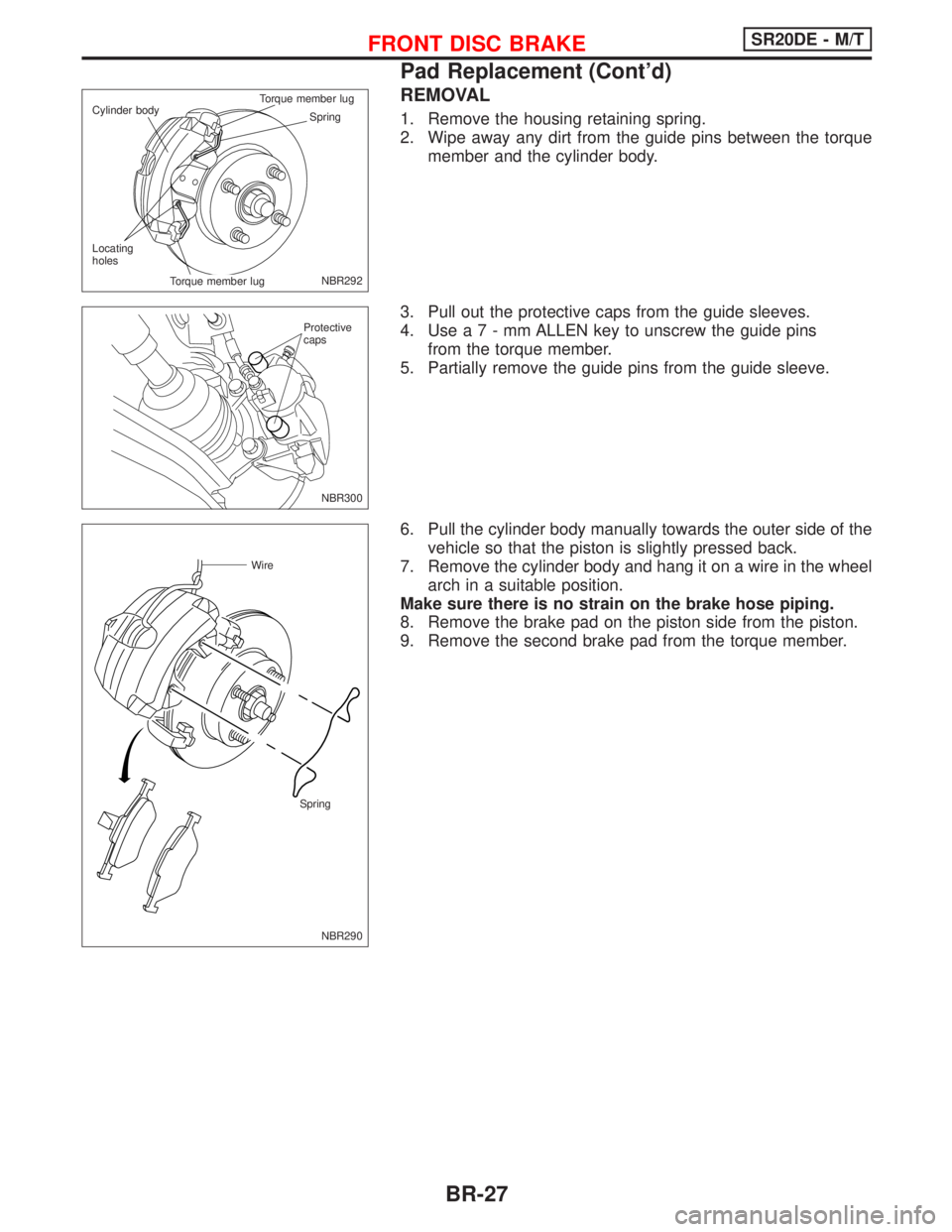
REMOVAL
1. Remove the housing retaining spring.
2. Wipe away any dirt from the guide pins between the torque
member and the cylinder body.
3. Pull out the protective caps from the guide sleeves.
4. Usea7-mmALLEN key to unscrew the guide pins
from the torque member.
5. Partially remove the guide pins from the guide sleeve.
6. Pull the cylinder body manually towards the outer side of the
vehicle so that the piston is slightly pressed back.
7. Remove the cylinder body and hang it on a wire in the wheel
arch in a suitable position.
Make sure there is no strain on the brake hose piping.
8. Remove the brake pad on the piston side from the piston.
9. Remove the second brake pad from the torque member.
NBR292 Spring Cylinder bodyTorque member lug.Torque member lug Locating
holes
NBR300 Protective
caps
NBR290
Wire
Spring
FRONT DISC BRAKESR20DE - M/T
Pad Replacement (Cont'd)
BR-27
Page 150 of 2267
CAUTION:
Do not use any sharp tools or cleaning agents which con-
tains mineral oil. Damage to the installation can occur.
10. Clean the cylinder body and guide grooves in the torque
member.
11. Check the dust cover and guide sleeves for damage.
12. Measure the amount of wear on the brake pad
Standard pad thickness:
11 mm (0.43 in)
Pad wear limit:
2.0 mm (0.079 in)
14. Press the piston fully back with a suitable tool.
CAUTION:
Carefully monitor brake fluid level to avoid brake fluid from
returning to the reservoir when pushing back the piston.
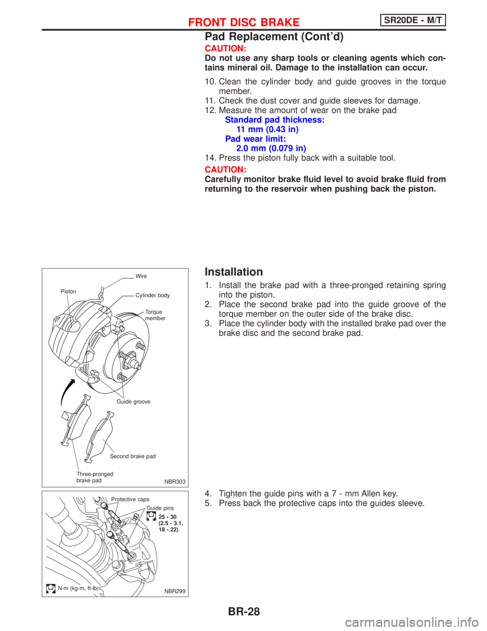
Installation
1. Install the brake pad with a three-pronged retaining spring
into the piston.
2. Place the second brake pad into the guide groove of the
torque member on the outer side of the brake disc.
3. Place the cylinder body with the installed brake pad over the
brake disc and the second brake pad.
4. Tighten the guide pins witha7-mmAllen key.
5. Press back the protective caps into the guides sleeve.
NBR303
Wire
Cylinder body
Torque
member
Guide groove
Second brake pad
Three-pronged
brake pad Piston
Guide pins
25-30
(2.5 - 3.1,
18 - 22) Protective caps
.N´m (kg-m, ft-lb)NBR299
FRONT DISC BRAKESR20DE - M/T
Pad Replacement (Cont'd)
BR-28
Page 151 of 2267
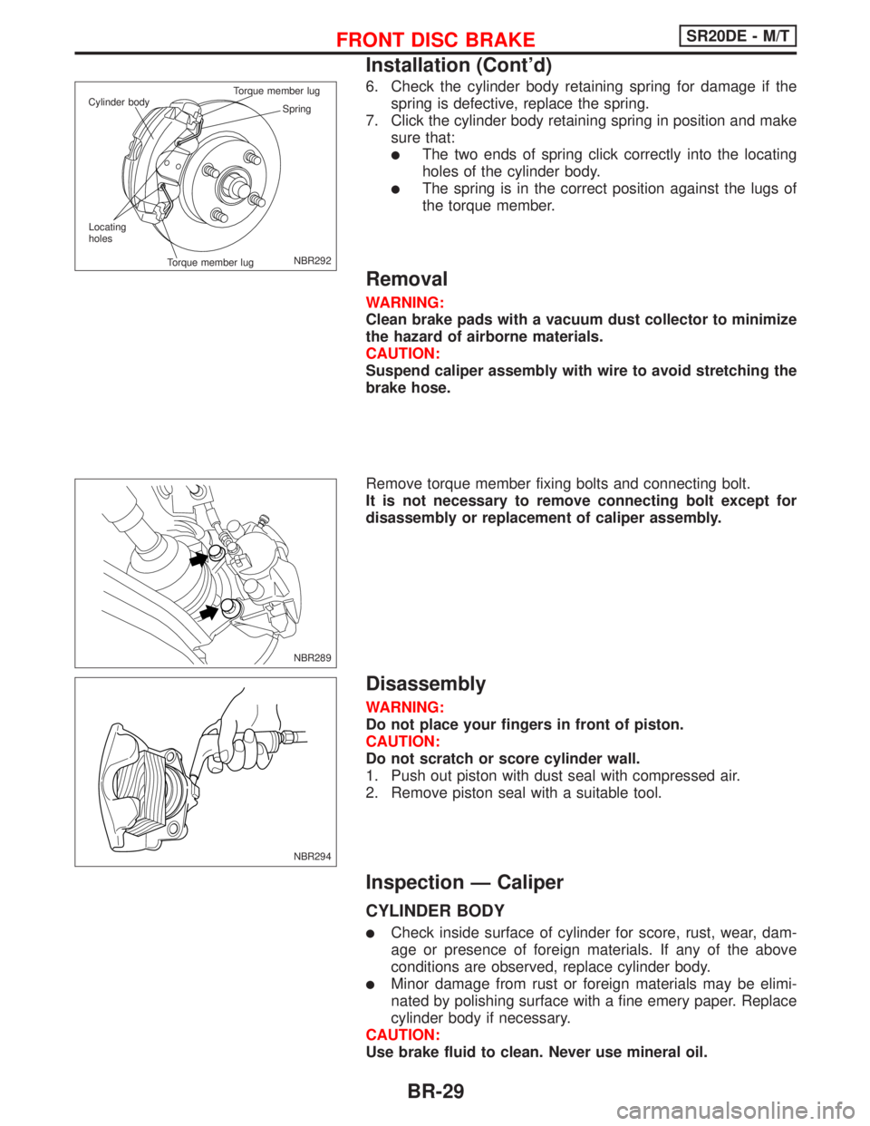
6. Check the cylinder body retaining spring for damage if the
spring is defective, replace the spring.
7. Click the cylinder body retaining spring in position and make
sure that:
lThe two ends of spring click correctly into the locating
holes of the cylinder body.
lThe spring is in the correct position against the lugs of
the torque member.
Removal
WARNING:
Clean brake pads with a vacuum dust collector to minimize
the hazard of airborne materials.
CAUTION:
Suspend caliper assembly with wire to avoid stretching the
brake hose.
Remove torque member fixing bolts and connecting bolt.
It is not necessary to remove connecting bolt except for
disassembly or replacement of caliper assembly.
Disassembly
WARNING:
Do not place your fingers in front of piston.
CAUTION:
Do not scratch or score cylinder wall.
1. Push out piston with dust seal with compressed air.
2. Remove piston seal with a suitable tool.
Inspection Ð Caliper
CYLINDER BODY
lCheck inside surface of cylinder for score, rust, wear, dam-
age or presence of foreign materials. If any of the above
conditions are observed, replace cylinder body.
lMinor damage from rust or foreign materials may be elimi-
nated by polishing surface with a fine emery paper. Replace
cylinder body if necessary.
CAUTION:
Use brake fluid to clean. Never use mineral oil.
NBR292 Spring Cylinder bodyTorque member lug
Torque member lug Locating
holes
NBR289
NBR294
FRONT DISC BRAKESR20DE - M/T
Installation (Cont'd)
BR-29
Page 152 of 2267
PISTON
CAUTION:
Piston sliding surface is plated. Do not polish with emery
paper even if rust or foreign materials are stuck to sliding
surface.
Check piston for score, rust, wear, damage or presence of for-
eign materials. Replace if any of the above conditions are
observed.
GUIDE PIN, BOLT, AND RETAINING SPRING
Check for wear, cracks or other damage. Replace if any of the
above conditions are observed.
FRONT DISC BRAKESR20DE - M/T
Inspection Ð Caliper (Cont'd)
BR-30
Page 213 of 2267
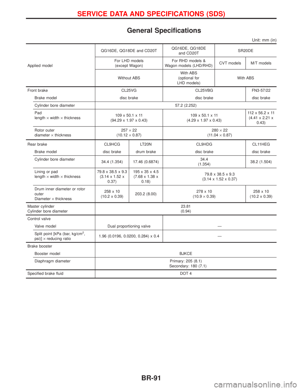
General Specifications
Unit: mm (in)
Applied modelQG16DE, QG18DE and CD20TQG16DE, QG18DE
and CD20TSR20DE
For LHD models
(except Wagon)For RHD models &
Wagon models (LHD/RHD)CVT models M/T models
Without ABSWith ABS
(optional for
LHD models)With ABS
Front brake CL25VG CL25VBG FN3-57/22
Brake model disc brake disc brake disc brake
Cylinder bore diameter 57.2 (2.252)
Pad
length´width´thickness109 x 50.1 x 11
(94.29 x 1.97 x 0.43)109 x 50.1 x 11
(4.29 x 1.97 x 0.43)112x56.2x11
(4.41 x 2.21 x
0.43)
Rotor outer
diameter´thickness257´22
(10.12´0.87)280´22
(11.04´0.87)
Rear brake CL9HCG LT20N CL9HDG CL11HEG
Brake model disc brake drum brake disc brake disc brake
Cylinder bore diameter
34.4 (1.354) 17.46 (0.6874)34.4
(1.354)38.2 (1.504)
Lining or pad
length´width´thickness79.8 x 38.5 x 9.3
(3.14 x 1.52 x
0.37)195x35x4.5
(7.68 x 1.38 x
0.18)79.8 x 38.5 x 9.3
(3.14 x 1.52 x 0.37)
Drum inner diameter or rotor
outer
Diameter´thickness258x10
(10.2 x 0.39)203.2 (8.00)278x10
(10.9´0.39)258x10
(10.2 x 0.39)
Master cylinder
Cylinder bore diameter23.81
(0.94)
Control valve
Valve model Dual proportioning valve Ð
Split point [kPa (bar, kg/cm
2,
psi)]´reducing ratio1.96 (0.0196, 0.0200, 0.284) x 0.4 Ð
Brake booster
Booster model BJKCE
Diaphragm diameter Primary: 205 (8.1)
Secondary: 180 (7.1)
Specified brake fluid DOT 4
SERVICE DATA AND SPECIFICATIONS (SDS)
BR-91