check engine NISSAN PULSAR 1987 Owners Manual
[x] Cancel search | Manufacturer: NISSAN, Model Year: 1987, Model line: PULSAR, Model: NISSAN PULSAR 1987Pages: 238, PDF Size: 28.91 MB
Page 125 of 238
Clutch 125
(3) Remove the nuts retaining the outer cable
flange to the vehicle bulkhead.
(4) Working inside the ve hicle, disconnect the
inner cable from the top of the clutch pedal. (5) Pull the clutch cable through the bulkhead
into the engine compartment. (6) Release the clip retaining the centre of the
clutch cable and remove the cable from the vehicle. (7) Check the inner cable for fraying, wear and
damage. Check the outer cable for kinks, wear and
damage. If necessary, renew the cable assembly. Installation is a reversal of the removal procedure
with attention to the following points:
(1) Lubricate the inner cable ends with lithium
base molybdenum disulphide grease prior to installa-
tion. (2) Tighten the nuts retaining the outer cable
flange to a torque of 11 Nm. (3) Check and if necessary , adjust the clutch
pedal height and free play as described under the
heading Clutch Adjustments.
6. CLUTCH ADJUSTMENTS
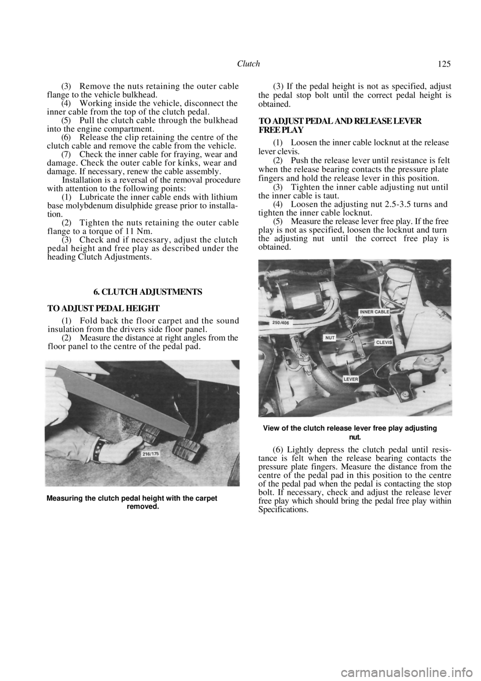
TO ADJUST PEDAL HEIGHT (1) Fold back the floor carpet and the sound
insulation from the drivers side floor panel.
(2) Measure the distance at right angles from the
floor panel to the centre of the pedal pad. (3) If the pedal height is not as specified, adjust
the pedal stop bolt until the correct pedal height is
obtained.
TO ADJUST PEDAL AND RELEASE LEVER
FREE PLAY
(1) Loosen the inner cable locknut at the release
lever clevis. (2) Push the release lever until resistance is felt
when the release bearing contacts the pressure plate
fingers and hold the release lever in this position.
(3) Tighten the inner cable adjusting nut until
the inner cable is taut.
(4) Loosen the adjusting nut 2.5-3.5 turns and
tighten the inner cable locknut. (5) Measure the release lever free play. If the free
play is not as specified, loosen the locknut and turn
the adjusting nut until the correct free play is
obtained.
View of the clutch release lever free play adjusting
nut.
(6) Lightly depress the clutch pedal until resis-
tance is felt when the release bearing contacts the
pressure plate fingers. Measure the distance from the
centre of the pedal pad in this position to the centre
of the pedal pad when the pedal is contacting the stop
bolt. If necessary, check and adjust the release lever
free play which should bring the pedal free play within
Specifications.
Measuring the clutch pedal height with the carpet
removed.
Page 126 of 238
126
MANUAL TRANSAXLE AND DRIVE SHAFTS
SPECIFICATIONS
TRANSAXLE
Type .....................................Five speed, synchromesh
on all forward gears
Model .......................................................... RS5F31A
Gear ratios: 1.6 liter -
First .......................................................... 3.333:1
Second...................................................... 1.955:1
Third......................................................... 1.286:1
Fourth....................................................... 0.975:1
Fifth.......................................................... 0.810:1
Reverse .................................................... 3.417:1
1.8 liter -
First .......................................................... 3.063:1
Second...................................................... 1.826:1
Third......................................................... 1.286:1
Fourth ....................................................... 0.975:1
Fifth.......................................................... 0.810:1
Reverse .................................................... 3.417:1
Gear end float:
Fifth...............................................0.18-0.41 mm
Second, third and fourth................0.20-0.40 mm
First ...............................................0.18-0.31 mm
Synchro ring to gear clearance:
Standard ............................................ 1.0-1.3 mm
Minimum ................................................. 0.7 mm
Turning torque (new bearings):
Differential assembly ........................ 3.9-7.8 Nm
Total differential and mainshaft __ 5.9-13.7 Nm
Differential and final drive:
Type ........................ Helical ring gear and pinion
Ratio......................................................... 4.167:1
Lubricant:
Grade ............................................. 80W-90 GL-4
Capacity ..................................................2.7 liters
DRIVE SHAFTS
C.V. joint lubrication:
Lubricant ........ Valvoline Special Moly EP grease
Amount ................................................. 40 grams
TORQUE WRENCH SETTINGS
Transaxle case retaining bolts ........
Cover plate to transaxle case .......................... 8.3 Nm
Input shaft bearing retainer bolts ..................... 21 Nm
Control bracket bolts ...................................... 8.3 Nm
Reverse check plug.......................................... 25 Nm
Ring gear to differential case........................... 88 Nm
Filler and drain plugs....................................... 34 Nm
Reverse lamps switch ...................................... 29 Nm
Upper and centre clutch housing to engine…...49 Nm
Lower clutch housing to engine ...................... 21 Nm
1. MANUAL TRANSAXLE AND DRIVE
SHAFT
TROUBLE SHOOTING
DIFFICULT GEAR CHANGE
(1) Faulty clutch or clutch release mechanism:
Check and adjust or overhaul the clutch or the clutch
release mechanism. (2) Loose control bracket retaining bolts: Dis-
mantle the transaxle and tighten the control bracket
retaining bolts. Apply Loctite or an equivalent to the
bolt threads to prevent a repeat of the problem.
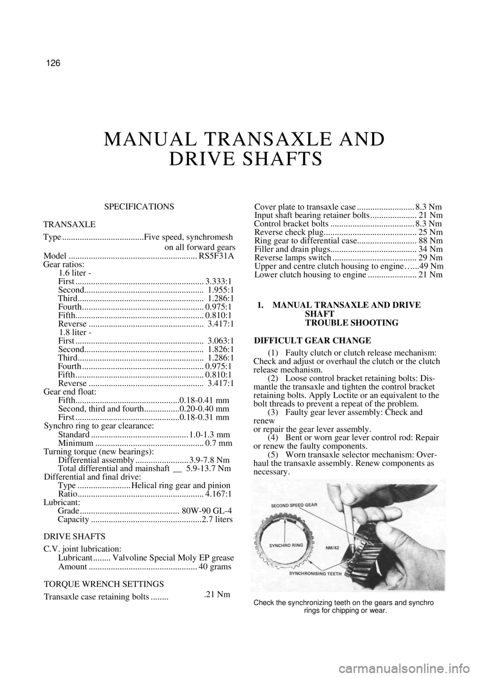
(3) Faulty gear lever assembly: Check and
renew
or repair the gear lever assembly. (4) Bent or worn gear lever control rod: Repair
or renew the faulty components. (5) Worn transaxle selector mechanism: Over-
haul the transaxle assembly. Renew components as
necessary.
.21 NmCheck the synchronizing teeth on the gears and synchro
rings for chipping or wear.
Page 127 of 238
Manual Transaxle and Drive Shafts 127
(6) Lubricating oil too thick: Drain the transaxle
and refill with the corre ct amount and grade of
lubricating oil. (7) Excessive end float in the mainshaft or input
shaft gears: Overhaul the transaxle.
NOTE: Check the clutch for correct opera-
tion. If reverse gear can be selected without
any gear clash this is a good indication that
the clutch is operating normally. Also check
that the correct type and grade of lubricating
oil is being used.
SLIPPING OUT OF GEAR
(1) Worn gear control rod assembly bushes:
Check and renew the worn components as necessary. (2) Faulty gear lever assembly: Check and renew
the faulty components. (3) Faulty synchroniser mechanism: Overhaul
the transaxle.
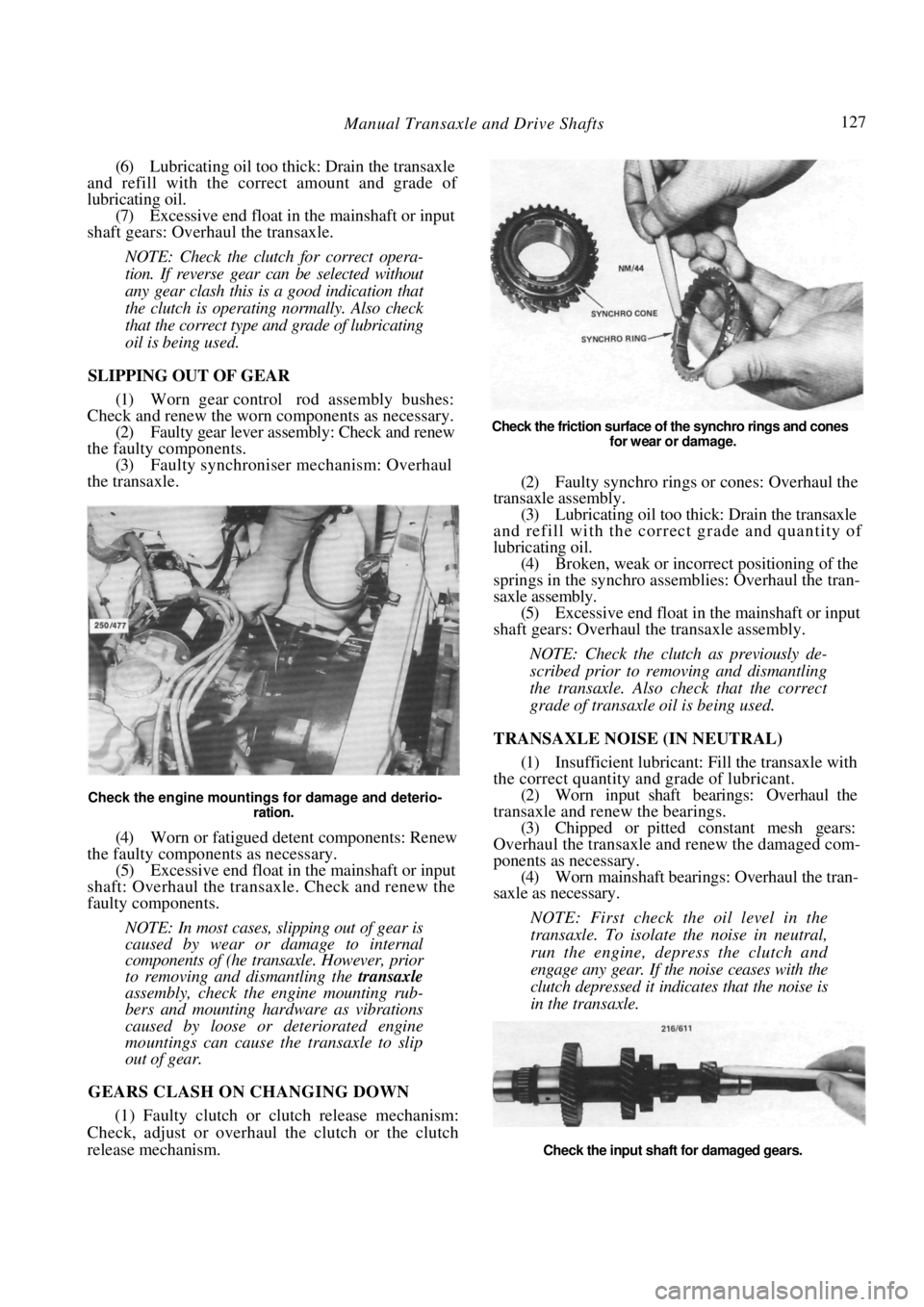
Check the engine mountings for damage and deterio-
ration.
(4) Worn or fatigued detent components: Renew
the faulty components as necessary.
(5) Excessive end float in the mainshaft or input
shaft: Overhaul the transaxle. Check and renew the
faulty components.
NOTE: In most cases, slipping out of gear is
caused by wear or damage to internal
components of (he tran saxle. However, prior
to removing and dismantling the transaxle
assembly, check the engine mounting rub-
bers and mounting hardware as vibrations
caused by loose or deteriorated engine
mountings can cause the transaxle to slip
out of gear.
GEARS CLASH ON CHANGING DOWN
(1) Faulty clutch or clutch release mechanism:
Check, adjust or overhaul the clutch or the clutch
release mechanism.
Check the friction surface of the synchro rings and cones
for wear or damage.
(2) Faulty synchro rings or cones: Overhaul the
transaxle assembly.
(3) Lubricating oil too thick: Drain the transaxle
and refill with the correct grade and quantity of
lubricating oil. (4) Broken, weak or incorrect positioning of the
springs in the synchro asse mblies: Overhaul the tran-
saxle assembly.
(5) Excessive end float in the mainshaft or input
shaft gears: Overhaul the transaxle assembly.
NOTE: Check the clutch as previously de-
scribed prior to removing and dismantling
the transaxle. Also check that the correct
grade of transaxle oil is being used.
TRANSAXLE NOISE (IN NEUTRAL)
(1) Insufficient lubricant: Fill the transaxle with
the correct quantity and grade of lubricant. (2) Worn input shaft bearings: Overhaul the
transaxle and renew the bearings. (3) Chipped or pitted constant mesh gears:
Overhaul the transaxle and renew the damaged com-
ponents as necessary. (4) Worn mainshaft bearings: Overhaul the tran-
saxle as necessary.
NOTE: First check the oil level in the
transaxle. To isolate the noise in neutral,
run the engine, depress the clutch and
engage any gear. If the noise ceases with the
clutch depressed it indicates that the noise is
in the transaxle.
Check the input shaft for damaged gears.
Page 129 of 238
Manual Transaxle and Drive Shafts 129
renewed as individual units. The C.V. joints are
lubricated in manufacture and need no attention in
service unless one of the r ubber boots is damaged. In
this case the joint can be cl eaned and repacked with
the recommended grease and a new boot installed.
From July 1989, Pulsar Q and Vector SSS manual
transaxle models are equipped with a limited slip
differential incorporating a viscous coupling. The
coupling is not repairable and must be renewed as an
assembly if unserviceable. A test procedure for the
viscous coupling is included in the text in this section.
3. TRANSAXLE ASSEMBLY
Special Equipment Required:
To Dismantle and Assemble — Puller set, press
and press plates, dial gauge
To Measure Mainshaft Turning Torque —
Suitable slotted adaptor and torque gauge
TO REMOVE AND INSTAL
(1) Raise the front of the vehicle and support it
on chassis stands.
(2) Remove the battery as described in the
Electrical System section. (3) Remove the drive shafts as described later in
this section. (4) Disconnect and remove the starter motor as
described in the Elect rical System section.
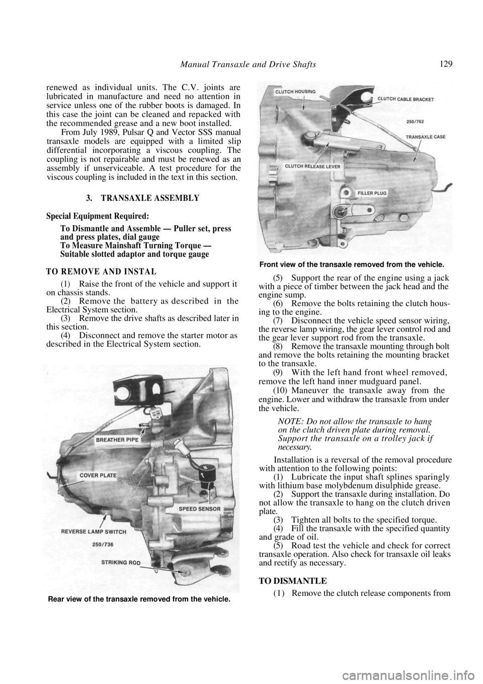
Front view of the transaxle removed from the vehicle.
(5) Support the rear of the engine using a jack
with a piece of timber between the jack head and the
engine sump.
(6) Remove the bolts retaining the clutch hous-
ing to the engine. (7) Disconnect the vehicle speed sensor wiring,
the reverse lamp wiring, the gear lever control rod and
the gear lever support rod from the transaxle. (8) Remove the transaxle mounting through bolt
and remove the bolts retaining the mounting bracket
to the transaxle.
(9) With the left hand front wheel removed,
remove the left hand inner mudguard panel. (10) Maneuver the transaxle away from the
engine. Lower and withdraw the transaxle from under
the vehicle.
NOTE: Do not allow the transaxle to hang
on the clutch driven plate during removal.
Support the transaxle on a trolley jack if
necessary.
Installation is a reversal of the removal procedure
with attention to the following points:
(1) Lubricate the input shaft splines sparingly
with lithium base molybdenum disulphide grease. (2) Support the transaxle during installation. Do
not allow the transaxle to hang on the clutch driven
plate. (3) Tighten all bolts to the specified torque.
(4) Fill the transaxle with the specified quantity
and grade of oil. (5) Road test the vehicle and check for correct
transaxle operation. Also ch eck for transaxle oil leaks
and rectify as necessary.
TO DISMANTLE
(1) Remove the clutch release components from Rear view of the transaxle removed from the vehicle.
Page 140 of 238
140
AUTOMATIC TRANSAXLE
SPECIFICATIONS
Make .............................................. JATCO RL3F01A
Type .....................3 speed and reverse epicyclic gear
train with lock up torque converter
Operation .................................... Automatic hydraulic
Lubricant:
Type....................................................... Dexron IT
Capacity................................................. 6.3 liters
TORQUE WRENCH SETTINGS
Drive plate to crankshaft bolls ........................60 Nm
Drive plate to torque converter bolts ..............49 Nm
Convener housing to engine ...........................22 Nm
Converter housing to transaxle ........................23 Nm
Transaxle sump to transaxle ............................. 7 Nm
Oil cooler pipe to transaxle .............................49 Nm
Selector shaft locknut .......................................42 Nm
Transaxle filter bolts.........................................12 Nm
1. AUTOMATIC TRANSAXLE TROUBLE SHOOTING
NO DRIVE IN D RANGE
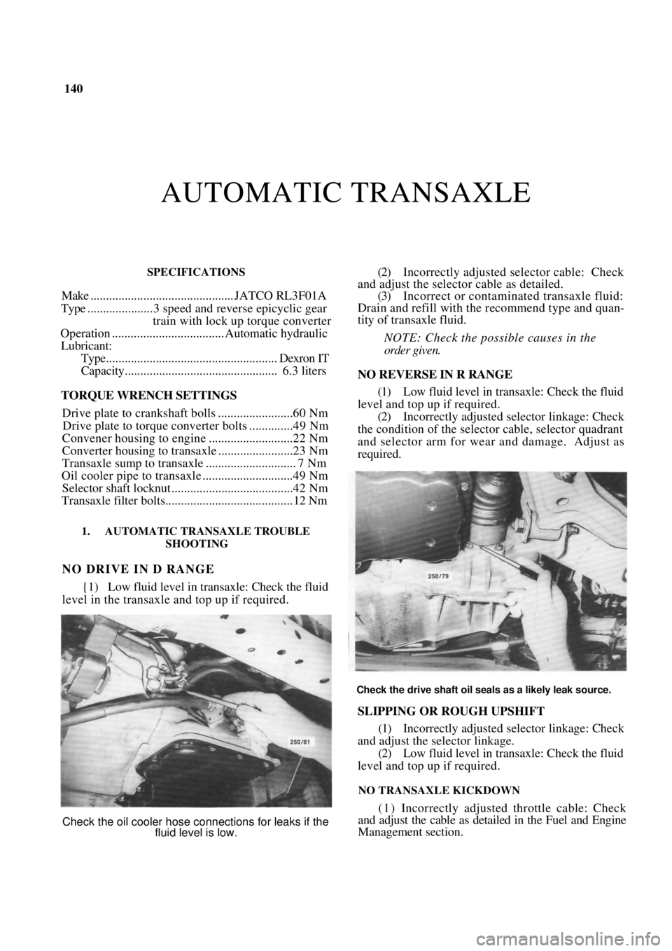
{1) Low fluid level in transaxle: Check the fluid
level in the transaxle and top up if required.
(2) Incorrectly adjusted selector cable: Check
and adjust the selector cable as detailed. (3) Incorrect or contaminated transaxle fluid:
Drain and refill with the recommend type and quan-
tity of transaxle fluid.
NOTE: Check the possible causes in the
order given.
NO REVERSE IN R RANGE
(1) Low fluid level in transaxle: Check the fluid
level and top up if required. (2) Incorrectly adjusted selector linkage: Check
the condition of the selector cable, selector quadrant
and selector arm for wear and damage. Adjust as
required.
Check the drive shaft oil seals as a likely leak source.
SLIPPING OR ROUGH UPSHIFT
(1) Incorrectly adjusted selector linkage: Check
and adjust the selector linkage. (2) Low fluid level in transaxle: Check the fluid
level and top up if required.
NO TRANSAXLE KICKDOWN
(1) Incorrectly adjusted throttle cable: Check
and adjust the cable as detailed in the Fuel and Engine
Management section.
Check the oil cooler hose connections for leaks if the
fluid level is low.
Page 141 of 238
Automatic Transaxle 141
(2) Incorrectly adjusted kickdown cable: Check
and adjust or renew the kickdown cable as required.
NOTE: Check and adjust the throttle cable
before adjusting the kickdown cable.
ENGINE WILL NOT START IN P OR N
RANGE OR WILL START IN ANY RANGE
(1) Neutral safety switch faulty: Adjust or renew
the neutral safety switch. (2) Incorrectly adjusted selector cable: Check
and adjust the selector cable as detailed.
2. DESCRIPTION
The automatic transaxle combines a fluid coup-
ling or torque converter with a fully automatic three
speed epicyclic gear system.
The transaxle provides th ree forward ratios and
one reverse. The hydraulic system consists of a single
pump and valv e arrangement.
The final drive or differential and the transaxle
use a common lubricant. The transaxle oil pan and
final drive drain plug will have to be removed to drain
the transaxle completely. Topping up or refilling is
done through the dipstick tube.
The gear selector lever is floor mounted and
connected to the transaxle by an adjustable cable. The
selector quadrant adjacent to the base of the lever is
marked P, R, N, D, 2, 1.
It is necessary for the selector lever to be in P or
N before the engine can be started. When testing or
tuning the engine, the handbrake must be firmly
applied and the selector lever placed in the P position,
otherwise the vehicle could move forward or back-
wards as the engine speed is increased.
For long distance towing the vehicle should be
towed with the front end raised.
It is not possible to start the engine by either
towing or pushing the vehicle.
The transaxle can be removed from the vehicle
without engine removal.
NOTE: As extensive knowledge and equip-
ment is required to overhaul the automatic
transaxle assembly, it is therefore not a
worthwhile repair proposition for the aver-
age person. However if the transaxle must
be overhauled by a specialist or be replaced
with a reconditioned unit, the removal and
installation procedure is fully described at
the end of this section.
3. TRANSAXLE FLUID
Only use the recommended transaxle fluid speci-
fied by the manufacturer when topping up or changing
the fluid in the system.
TO CHECK AND TOP UP
NOTE: The fluid level should be checked
after approximately 5 minutes driving on
the road when the engine has achieved its
normal operating temperature of approxi-
mately 65 deg C.
(1) Place the vehicle on a level floor and open
the engine bonnet.
NOTE: When working on the automatic
transaxle cleanliness is very important. Do
not reuse transaxle fluid and do not allow
foreign matter to enter the filler opening.
(2) Clean around the top of the dipstick to
ensure that no dirt or foreign matter can enter the
dipstick tube.
(3) Place the selector in the P position and
firmly apply the handbrake. (4) Move the selector thro ugh each gear return-
ing it to the P position.
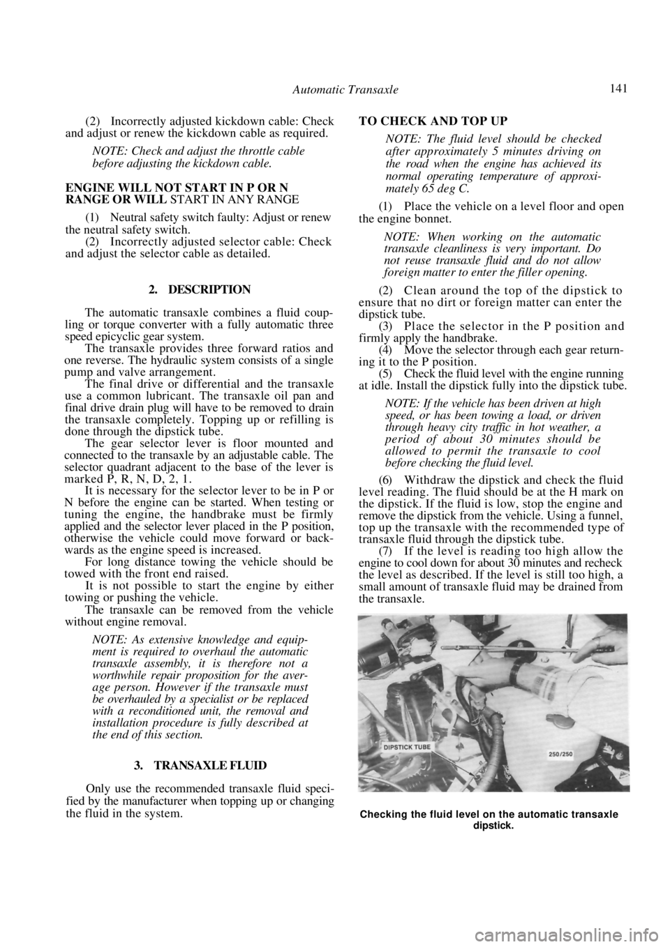
(5) Check the fluid level with the engine running
at idle. Install the dipstick fully into the dipstick tube.
NOTE: If the vehicle has been driven at high
speed, or has been towing a load, or driven
through heavy city traffic in hot weather, a
period of about 30 minutes should be
allowed to permit the transaxle to cool
before checking the fluid level.
(6) Withdraw the dipstick and check the fluid
level reading. The fluid should be at the H mark on
the dipstick. If the fluid is low, stop the engine and
remove the dipstick from the vehicle. Using a funnel,
top up the transaxle with the recommended type of
transaxle fluid through the dipstick tube. (7) If the level is reading too high allow the
engine to cool down for about 30 minutes and recheck
the level as described. If the level is still too high, a
small amount of transaxle fluid may be drained from
the transaxle.
Checking the fluid level on the automatic transaxle
dipstick.
Page 142 of 238
142 Automatic Transaxle
(8) Install the dipstick and start the engine and
recheck the fluid level.
NOTE; Do not overfill the transaxle or
foaming and unsatisfactory operation of the
transaxle will result.
TO DRAIN AND REFILL
This is not a normal maintenance and lubrication
procedure. It is only necessary to drain the complete
system, including the torq ue converter and the oil
cooler, when the transaxle assembly is removed for
overhaul or the renewal of transaxle components such
as bearings, clutches or as semblies. When this condi-
tion arises, the torque converter and the cooler should
be cleaned and flushed to remove any dirt or sludge.
After transaxle overhaul, install approximately 6
liters of new transaxle fluid, and top up as previously
described.
4. BRAKE BAND
Band adjustment is not a normal maintenance
procedure.
The adjustment entails removal of the valve body
and for this reason the vehicle should be taken to an
authorized dealer.
5. KICKDOWN CABLE
TO ADJUST
(1) On models with a 1.6 liter engine, remove
the air cleaner assembly. (2) With the aid of an assistant, ensure that the
throttle valve is fully open when the throttle pedal is
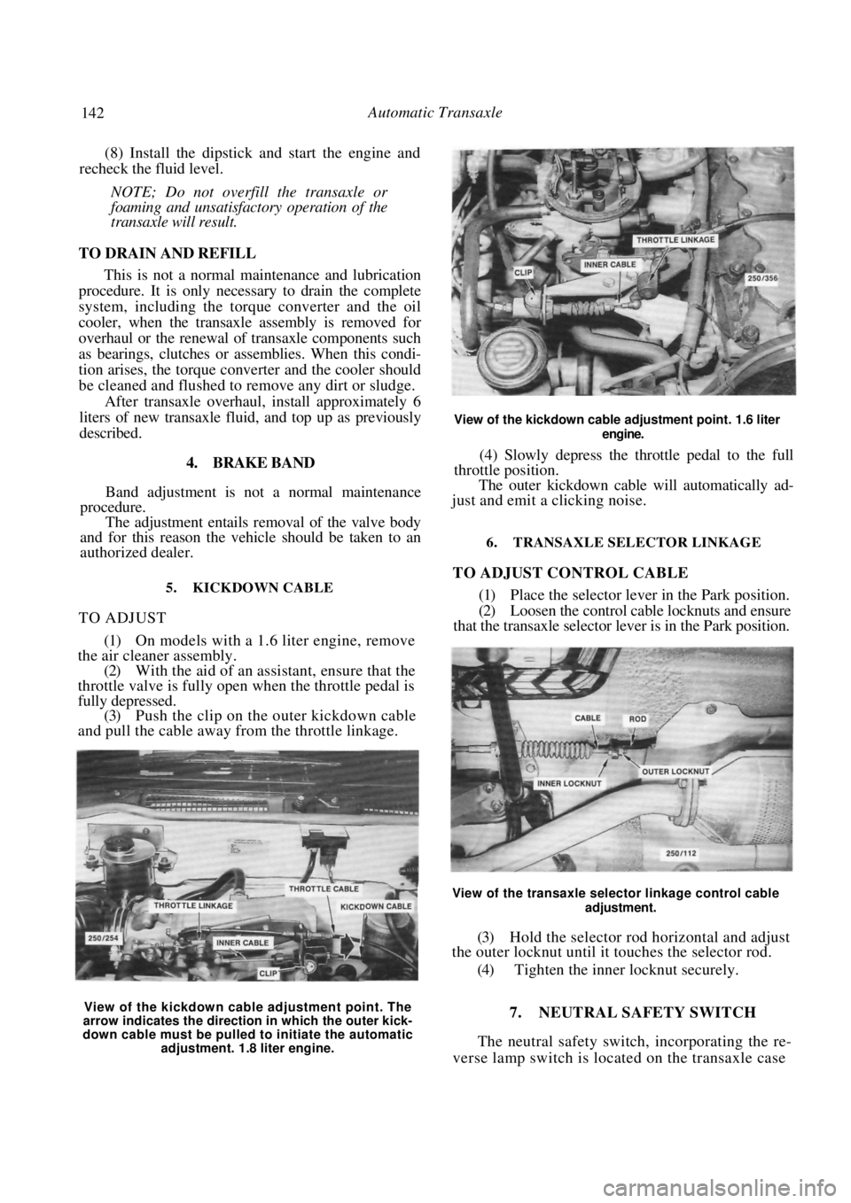
fully depressed. (3) Push the clip on the outer kickdown cable
and pull the cable away from the throttle linkage.
View of the kickdown cable adjustment point. 1.6 liter
engine.
(4) Slowly depress the throttle pedal to the full
throttle position.
The outer kickdown cable will automatically ad-
just and emit a clicking noise.
6. TRANSAXLE SELECTOR LINKAGE
TO ADJUST CONTROL CABLE
(1) Place the selector lever in the Park position.
(2) Loosen the control cable locknuts and ensure
that the transaxle selector lever is in the Park position.
View of the transaxle selector linkage control cable
adjustment.
(3) Hold the selector rod horizontal and adjust
the outer locknut until it touches the selector rod.
(4) Tighten the inner locknut securely.
7. NEUTRAL SAFETY SWITCH
The neutral safety switch, incorporating the re-
verse lamp switch is located on the transaxle case
View of the kickdown cable adjustment point. The
arrow indicates the direction in which the outer kick-
down cable must be pulled to initiate the automatic adjustment. 1.8 liter engine.
Page 143 of 238
Automatic Transaxle 143
facing towards the radiator support panel at the front
of the vehicle.
The neutral safety switch allows electrical current
to pass to the starter circ uit only when the selector
lever is in the Park or Neutral position. The switch is
adjustable but non-repairable.
TO TEST
(1) Disconnect the neutral safety switch wiring
connector.
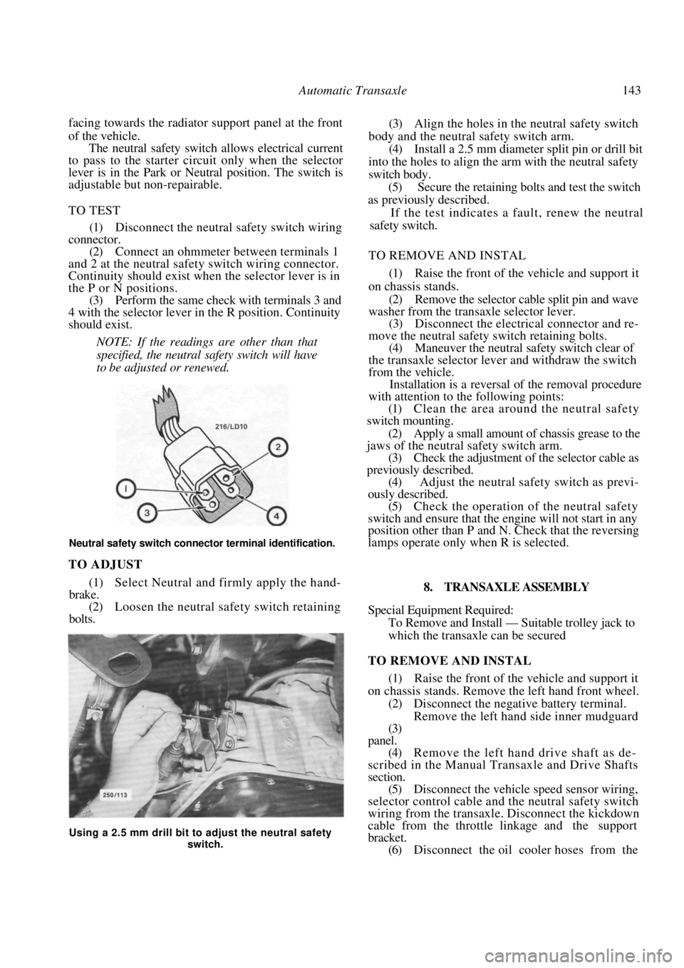
(2) Connect an ohmmeter between terminals 1
and 2 at the neutral safety switch wiring connector.
Continuity should exist when the selector lever is in
the P or N positions. (3) Perform the same check with terminals 3 and
4 with the selector lever in the R position. Continuity
should exist.
NOTE: If the readings are other than that
specified, the neutral safety switch will have
to be adjusted or renewed.
Neutral safety switch connector terminal identification.
TO ADJUST
(1) Select Neutral and firmly apply the hand-
brake. (2) Loosen the neutral safety switch retaining
bolts.
(3) Align the holes in the neutral safety switch
body and the neutral safety switch arm. (4) Install a 2.5 mm diameter split pin or drill bit
into the holes to align the arm with the neutral safety
switch body. (5) Secure the retaining bolts and test the switch
as previously described.
If the test indicates a fault, renew the neutral
safety switch.
TO REMOVE AND INSTAL
(1) Raise the front of the vehicle and support it
on chassis stands. (2) Remove the selector cable split pin and wave
washer from the transaxle selector lever.
(3) Disconnect the electric al connector and re-
move the neutral safety switch retaining bolts. (4) Maneuver the neutral safety switch clear of
the transaxle selector lever and withdraw the switch
from the vehicle. Installation is a reversal of the removal procedure
with attention to the following points:
(1) Clean the area around the neutral safety
switch mounting.
(2) Apply a small amount of chassis grease to the
jaws of the neutral safety switch arm. (3) Check the adjustment of the selector cable as
previously described. (4) Adjust the neutral safety switch as previ-
ously described.
(5) Check the operation of the neutral safety
switch and ensure that the engine will not start in any
position other than P and N. Check that the reversing
lamps operate only when R is selected.
8. TRANSAXLE ASSEMBLY
Special Equipment Required:
To Remove and Install — Suitable trolley jack to
which the transaxle can be secured
TO REMOVE AND INSTAL
(1) Raise the front of the vehicle and support it
on chassis stands. Remove the left hand front wheel.
(2) Disconnect the negative battery terminal. Remove the left hand side inner mudguard
(3)
panel.
(4) Remove the left hand drive shaft as de-
scribed in the Manual Tran saxle and Drive Shafts
section. (5) Disconnect the vehicle speed sensor wiring,
selector control cable and the neutral safety switch
wiring from the transaxle. Disconnect the kickdown
cable from the throttle linkage and the support
bracket. (6) Disconnect the oil cooler hoses from the
Using a 2.5 mm drill bit to adjust the neutral safety
switch.
Page 144 of 238
144 Automatic Transaxle
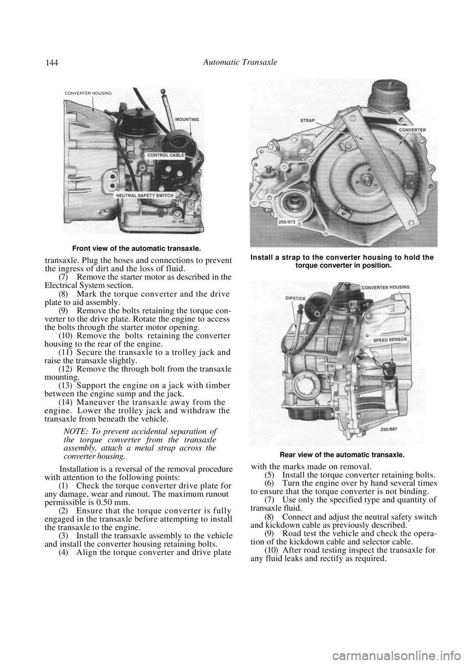
Front view of the automatic transaxle.
transaxle. Plug the hoses and connections to prevent
the ingress of dirt and the loss of fluid.
(7) Remove the starter motor as described in the
Electrical System section.
(8) Mark the torque converter and the drive
plate to aid assembly.
(9) Remove the bolts retaining the torque con-
verter to the drive plate. Rotate the engine to access
the bolts through the starter motor opening. (10) Remove the bolts retaining the converter
housing to the rear of the engine. (11) Secure the transaxle to a trolley jack and
raise the transaxle slightly. (12) Remove the through bolt from the transaxle
mounting.
(13) Support the engine on a jack with timber
between the engine sump and the jack. (14) Maneuver the transaxle away from the
engine. Lower the trolley jack and withdraw the
transaxle from beneath the vehicle.
NOTE: To prevent accidental separation of
the torque converter from the transaxle
assembly, attach a metal strap across the
converter housing.
Installation is a reversal of the removal procedure
with attention to the following points:
(1) Check the torque converter drive plate for
any damage, wear and runout. The maximum runout
permissible is 0.50 mm.
(2) Ensure that the torque converter is fully
engaged in the transaxle be fore attempting to install
the transaxle to the engine. (3) Install the transaxle assembly to the vehicle
and install the converter housing retaining bolts. (4) Align the torque converter and drive plate
Install a strap to the converter housing to hold the
torque converter in position.
Rear view of the automatic transaxle.
with the marks made on removal.
(5) Install the torque converter retaining bolts.
(6) Turn the engine over by hand several times
to ensure that the torque converter is not binding. (7) Use only the specified type and quantity of
transaxle fluid.
(8) Connect and adjust the neutral safety switch
and kickdown cable as previously described.
(9) Road test the vehicle and check the opera-
tion of the kickdown cable and selector cable. (10) After road testing inspect the transaxle for
any fluid leaks and rectify as required.
CONVERTER HOUSING
Page 148 of 238
148 Steering — Part 2
3. STEERING COLUMN
Special Equipment Required:
To Remove Steering Wheel — Steering wheel
puller
TO REMOVE AND INSTAL
(1) Disconnect the negative battery terminal.
(2) Working in the engine compartment, mark
the relationship between the steering shaft universal
coupling joint and the steering gear pinion shaft. (3) Remove the pinch bolts from the universal
joint. (4) Working inside the vehi cle, remove the steer-
ing wheel as previously described. (5) Remove the steering column shroud screws,
unclip the lower and upper covers and remove them
from the steering column. (6) Disconnect all the steering column wiring
connectors. (7) Remove the lower trim from underneath the
steering column.
(8) Fold back the insulator and remove the nuts
from the steering colu mn floor bracket.
(9) Remove the nuts from the lower steering
column bracket. (10) Remove the bolts from the tilt bracket
assembly. (11) Maneuver the steering column from the
vehicle.
Installation is a reversal of the removal procedure
with attention to the following points:
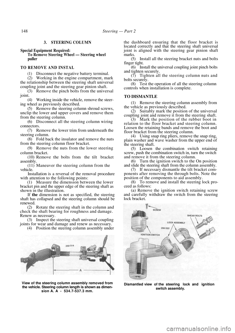
(1) Measure the dimension between the lower
bracket pin and the upper edge of the steering shaft as
shown in the illustration.
If the dimension is not as specified, the steering
shaft has collapsed and the steering column should be
renewed.
(2) Rotate the steering shaft in the column and
check the shaft bearing for roughness and damage.
Renew as necessary. (3) Inspect the steering shaft universal coupling
joints for wear and damage and renew as necessary. (4) Position the steering column assembly under
the dashboard ensuring that the floor bracket is
located correctly and that the steering shaft universal
joint is aligned with the steering gear pinion shaft
marks.
(5) Install all the steering bracket nuts and bolts
finger tight. (6) Install the universal coupling joint pinch bolts
and tighten securely.
(7) Tighten all the stee ring column nuts and
bolts securely. (8) Test the operation of all the steering column
controls when installation is complete.
TO DISMANTLE
(1) Remove the steering column assembly from
the vehicle as previously described. (2) Suitably mark the position of the universal
coupling joint and remove it from the steering shaft. (3) Mark the position of the rubber boot in
relation to the floor bracket and steering column.
Loosen the retaining bands and remove the boot and
floor bracket from th e steering column.
(4) Using snap ring pliers, remove the snap ring,
plain washer and wave washer from the upper end of
the steering shaft. (5) Loosen the combination switch retaining
screw, push the combination switch in, turn the switch
and remove it from the steering column. (6) Turn the ignition switch to the On position
and slide the steering shaft from the column assembly. (7) If necessary dismantle the tilt bracket com-
ponents after removing the through bolts. Note the
position of the components to aid assembly. (8) To remove and install the steering lock pro-
ceed as follows: (a) Remove the ignition switch retaining screw
and carefully withdraw the switch from the steering
lock bracket.
View of the steering column assembly removed from
the vehicle. Steering column length is shown as dimen- sion A. A - 534.7-537.3 mm. Dismantled view of the steering lock and ignition
switch assembly.