torque NISSAN PULSAR 1987 Repair Manual
[x] Cancel search | Manufacturer: NISSAN, Model Year: 1987, Model line: PULSAR, Model: NISSAN PULSAR 1987Pages: 238, PDF Size: 28.91 MB
Page 155 of 238

Steering — Part 3 155
(4) Support the rack carefully and lever back the
tabs of the ball housing lock washers. To prevent
damage to the steering gear, avoid any impact to the
steering rack.
(5) Holding the rack with an adjustable spanner,
unscrew the ball housings from the rack using a
Stillsons wrench. Remove and discard the lock wash-
ers. Installation is a reversal of the removal procedure
with attention to the following points:
(1) Install the new lock washer to the
rack,
ensuring that the lockwasher tangs are located in the
rack end. (2) Install the ball housing as semblies to the rack.
Tighten the ball housings to the specified torque and
secure by bending the lock washer. (3) Before installing the rubber boots ensure that
the vent holes, located towards each end of the rack
near the ball housings, are clear. If necessary clear the
hole with a suitable probe. (4) Apply sealant to the la rge end of the rubber
boot and grease to the small end. and install the boots,
being careful not to damage or twist them. Secure the boots with the clamps and clip
s ensuring that the clips
are facing downwards.
(5) Install the t i e rod end locknuts and tie rod
ends to the t i e rod. Install the t i e rod ends the same
number of turns noted on removal. Tighten the lock-
nuts to the specified torque.
Install the power steerin g gear assembly to the
vehicle as described under the previous heading and
bleed the system as described under the heading In
Car Adjustments, Checks and Minor Repairs.
TO RENEW RUBBER BOOTS
The procedure to renew the rubber boots is fully
covered in the Manual Steering section under the
Steering Gear Assembly heading.
TO RENEW TIE ROD ENDS
The procedure to renew the t i e rod ends is fully
covered in the Manual Steering section under the
Steering Gear Assembly heading.
Page 156 of 238

156
FRONT SUSPENSION
SPECIFICATIONS
Type.................. Independent MacPherson strut with
coil springs and control arms
Shock absorber .................. Hydraulic, non-repairable
Hub bearing end float (maximum) ............. 0.05 mm
Ball joint axial play (maximum) ....................0.7 mm
Ball joint turning torque (used)...............0.5-4.9 Nm
Wheel alignment:
Toe in ..................................................... 0-2 mm
Camber ........................................- 0 ° 1 0 ' ± 4 5 '
Caster ..............................................1 ° 1 0 ' ± 4 5 '
King pin inclination..................... 1 3 ° 5 5 ' ± 4 5 '
TORQUE WRENCH SETTINGS
Hub bearing nut..................................... 196-235 Nm
Suspension unit to steering knuckle nut ...... 118 Nm
Suspension unit to body nuts ......................... 29 Nm
Piston rod nut .................................................. 72 Nm
Brake caliper to steering knuckle bolts ........... 52 Nm
Ball joint to steering knuckle bolt ................... 86 Nm
Control arm bracket bolts ............................... 98 Nm
Control arm pivot bolt ................................ 118 Nm
Stabiliser bar link nuts..................................... 44 Nm
Stabiliser bar bracket bolts .............................. 21 Nm
1. FRONT SUSPENSION TROUBLE
SHOOTING
FRONT END NOISE
(1) Loose upper suspension mounting or piston
rod: Tighten the mounting or piston rod nuts. (2) Loose or worn suspension unit lower ball
joint: Tighten or renew the lower ball joint.
(3) Noise in the suspension unit: Renew the
faulty suspension unit, preferably in pairs.
(4) Worn or loose steering gear: Overhaul the
steering gear assembly. (5) Worn front hub bearings: Renew the hub
bearings:
(6) Loose or defective stab ilizer bar, control arm
or mountings: Check, tighten or renew the mounting
rubbers.
Check the ball joints for wear and deterioration.
(7) Worn stabilizer bar link ball joints: Renew
the stabilizer bar links.
(8) Drive shafts worn or insufficiently lubri-
cated: Check the lubricant and the dust boots and
renew as necessary. (9) Drive shaft splines in the hub or the
differential worn or dama ged: Check and renew as
necessary.
NOTE: To check the front suspension com-
ponents for wear, raise the front of the
vehicle, support it on chassis stands and
allow both front wheel to hang free. With an
assistant pushing and pulling the front
wheels in and out at the top and then at the
bottom, check for excessive looseness at the
front hub bearings and lower control arm
inner pivot bushes. Noise or vibration in the
front end can also be caused by excessive
tire or wheel unbalance. Drive shaft joint
noise is usually more pronounced when
moving slowly with the steering on full lock.
POOR OR ERRATIC ROAD HOLDING
ABILITY
(1) Low or uneven tire pressures: Inflate the
tires to the recommended pressures.
(2) Defective suspension unit: Renew the faulty
unit, preferably in pairs.
Page 158 of 238

158 Front Suspension
Installed view of the front suspension. When using a floor jack locate the head of the jack on the crossmember.
(2) Remove the cap, split pin, castellated re-
tainer and with the aid of an assistant applying the
brakes, loosen and remove the hub nut.
(3) Remove the split pin and the castellated nut
retaining the tie rod end to the steering knuckle. (4) Disconnect the tie rod end from the steering
knuckle using a suitable puller. Alternatively place a
suitable dolly or hammer against one side of the
steering knuckle eye and strike the opposite side with
a hammer.
(5) Remove the brake caliper anchor plate bolts,
withdraw the caliper from the disc and support it with
a piece of wire inside the inner mudguard. Ensure that
the brake hose is not twisted.
(6) Withdraw the brake disc from the hub.
(7) Loosely install the hub nut and tap on the nut
with a soft faced hammer to separate the drive shaft
from the hub. (8) Place a mark on the suspension unit to
steering knuckle cam head bolt to ensure correct wheel
alignment on assembly. (9) Remove the steering knuckle to suspension
unit nuts and bolts. (10) Remove the split pin and the castellated nut
retaining the lower ball joint stud to the steering
knuckle. (11) Disconnect the ball joint stud from the steering knuckle using a suitable puller or alternatively
place a suitable dolly or hammer against one side of
the steering knuckle eye and strike the opposite side
with a hammer.
(12)
Withdraw the steering knuckle from the
vehicle taking care not to drop the drive shaft or
damage its boot. (13) Clean and check the steering knuckle for
wear, cracks and damage. (14) If necessary, dismantle the hub and check
the bearing assembly using the dismantling procedure
described later in this section. Installation is a reversal of the removal procedure
with attention to the following points:
(1) Install the steering knuckle and hub assembly
over the drive shaft and loosely install the ball joint
stud nut and the suspension unit to knuckle bolts and
nuts.
(2) Ensure that the suspension unit to steering
knuckle cam head bolt mark s are aligned and tighten
the retaining nuts to the specified torque.
NOTE: If the cam head bolt is not installed
in its original position, a wheel alignment
should be performed.
(3) Tighten the ball joint to steering knuckle stud
bolt to the specified torque.
Page 159 of 238

Front Suspension 159
(4) Install the tie rod end to the steering knuckle
and tighten the castellated nut securely. Install a
new
split pin.
(5) Install the brake disc to the hub.
(6) Install the brake caliper to the steering
knuckle and tighten the retaining bolts to the specified
torque. (7) Install the hub nut and washer to the
drive
shaft and with the aid of an assistant applying the
brakes, tighten the hub nut to the specified torque. (8) Install the hub nut retainer and a new
split
pin to the drive shaft. (9) Check the hub end float as described later in
this section. (10) Install the fron t wheel and lower the vehicle
to the ground.
TO DISMANTLE
NOTE: The front wheel bearing assembly is
non-serviceable. If the wheel bearing is dis-
mantled for any reason it should be re-
newed.
(1) Remove the steering knuckle from the vehi-
cle as previously described. (2) Hold the steering knuckle assembly in a vice
with soft jaw guards. (3) Using a hammer and a suitable pipe or tube
that pushes on the inside of the hub, drive out the
wheel hub and outside inner race from the steering
knuckle assembly. (4) Using snap ring pliers, remove the snap ring
that retains the outer bearing race from the wheel side
of the steering knuckle. (5) Using a suitable press and press plates,
support the steering knuckle with the outside face
downwards. To aid in dismantling, position the inside
inner race in the bearing and press the assembly from
the steering knuckle. Discard the bearing assembly. (6) Using a bearing puller and a press, remove
the inner race from the hub assembly. If the inner race cannot be removed from the hub
in this manner, it may be necessary to grind the race
using an angle grinder and split the race using a cold
chisel.
(7) Thoroughly clean and dry the steering
knuckle and hub in a suitable solvent. (8) Inspect all the components for wear, damage
and cracks and renew if necessary.
TO ASSEMBLE
Assembly is a reversal of the dismantling proce-
dure with attention to the following points:
(1) Apply grease to the oil seal lips of the new
bearing assembly.
NOTE: Ensure that (he inside of the outer
race of the bearing is precoated with wheel
bearing grease. If necessary, pack the outer
race of the wheel bearing with wheel bearing
grease after it is installed to the steering
knuckle.
(2) Using the press and press plates, support the
steering knuckle with the outside face uppermost.
Using a suitable diameter steel tube that contacts on
the outer race only, press the outer race full into the
steering knuckle.
(3) Install the snap ring to the groove in the
steering knuckle.
(4) Install the inner races to the steering
knuckle
and support the inner race on the press using a
suitable tube or mandrel. (5) Using the press and a suitable tube press the
hub assembly into the steerin g knuckle. When using
the press ensure that the pressing force does not
exceed 29 kN. (6) With the press exerting a force of 44.1 kN
rotate the steering knuckle from side to side several
turns to ensure that the wh eel bearings are operating
smoothly.
(7) Install the steering knuckle to the vehicle
as
previously described.
TO CHECK HUB END FLOAT
(1) Raise the front of the vehicle and support it
on chassis stands. Remove the front wheel.
(2) Mount the dial gauge on the steering knuckle
so that the dial gauge plunger is against the wheel hub.
(3) Zero the dial gauge and attempt to move the
hub in and out. Total hub e nd float should not exceed
0.05 mm. (4) Renew the wheel bearing as previously de-
scribed if necessary.
4. SUSPENSION UNIT
Special Equipment Required:
To Dismantle — Spring compressor
TO REMOVE AND DISMANTLE
(1) Raise the front of the vehicle and support it
on chassis stands. Remove the front wheels.
Dismantled view of the steering knuckle and hub
components.
Page 161 of 238
Front Suspension 161
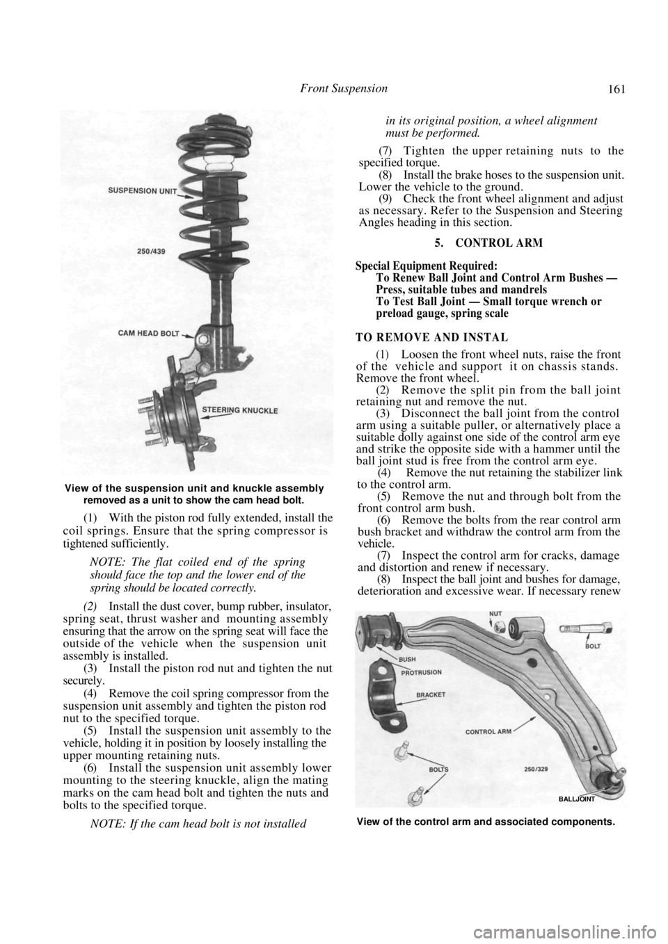
View of the suspension unit and knuckle assembly removed as a unit to show the cam head bolt.
(1) With the piston rod fully extended, install the
coil springs. Ensure that the spring compressor is
tightened sufficiently.
NOTE: The flat coiled end of the spring
should face the top and the lower end of the
spring should be located correctly.
(2) Install the dust cover, bump rubber, insulator,
spring seat, thrust washer and mounting assembly
ensuring that the arrow on the spring seat will face the
outside of the vehicle when the suspension unit
assembly is installed.
(3) Install the piston rod nut and tighten the nut
securely.
(4) Remove the coil spring compressor from the
suspension unit assembly and tighten the piston rod
nut to the specified torque. (5) Install the suspension unit assembly to the
vehicle, holding it in position by loosely installing the
upper mounting retaining nuts. (6) Install the suspension unit assembly lower
mounting to the steering knuckle, align the mating
marks on the cam head bolt and tighten the nuts and
bolts to the specified torque.
NOTE: If the cam head bolt is not installed
in its original position, a wheel alignment
must be performed.
(7) Tighten the upper retaining nuts to the
specified torque.
(8) Install the brake hoses to the suspension unit.
Lower the vehicle to the ground.
(9) Check the front wheel alignment and adjust
as necessary. Refer to the Suspension and Steering
Angles heading in this section.
5. CONTROL ARM
Special Equipment Required:
To Renew Ball Joint and Control Arm Bushes —
Press, suitable t ubes and mandrels
To Test Ball Joint — Small torque wrench or
preload gauge, spring scale
TO REMOVE AND INSTAL
(1) Loosen the front wheel nuts, raise the front
of the vehicle and support it on chassis stands.
Remove the front wheel.
(2) Remove the split pin from the ball joint
retaining nut and remove the nut.
(3) Disconnect the ball joint from the control
arm using a suitable puller, or alternatively place a
suitable dolly against one si de of the control arm eye
and strike the opposite side with a hammer until the
ball joint stud is free from the control arm eye. (4) Remove the nut retaining the stabilizer link
to the control arm.
(5) Remove the nut and through bolt from the
front control arm bush. (6) Remove the bolts from the rear control arm
bush bracket and withdraw the control arm from the
vehicle. (7) Inspect the control arm for cracks, damage
and distortion and renew if necessary. (8) Inspect the ball joint and bushes for damage,
deterioration and excessive wear. If necessary renew
BALLJOINT
View of the control arm and associated components.
Page 162 of 238

162 Front Suspension
the ball joint or bushes as described later in this
section.
Installation is a reversal of the removal procedure
with attention to the following points:
(1) When installing the control arm bush
bracket, ensure that the protrusion on the bracket is
towards the inside of the vehicle.
(2) Do not fully tighten the control arm bush
bolts and through bolt nut until the curb weight of the
vehicle is on the suspension.
NOTE: Curb weight is with the vehicle
unladen except for a full tank of fuel and
normal amounts of oil and water and with
the spare lyre, jack and hand tools in their
normal positions.
(3) Tighten the ball joint nut to the specified
torque and retain with a new split pin.
TO CHECK AND RENEW BALL JOINT
(1) Remove the control arm from the vehicle as
previously described.
(2) Install the ball joint nut and turn the ball
joint at least ten revolutions to ensure that the ball
joint is correctly seated. (3) Using a spring scale with the hook placed
over the split pin hole, check the ball joint swinging
torque. A new ball joint should measure 15.7-80.4 N
and a used ball joint should measure 7.8-80.4 N.
Renew the ball joint if necessary. (4) Using a small torque wrench or preload
gauge, measure the force requi red to rotate the ball
joint. A new ball joint should measure between
1.0-4.9 Nm and a used ball joint should measure
between 0.5-4.9 Nm. Renew the ball joint if neces-
sary.
(5) To renew the ball joint, remove the snap ring
from the stud end of the ball joint using snap ring
pliers. (6) Support the control arm in a press, ball joint
stud uppermost, with a suitable tube that is large
enough for the ball joint to pass through. (7) Press the ball joint out from the control arm.
(8) Press a new ball joint into the control arm
using a suitable tube that pushes on the outer circum-
ference of the joint only.
(9) Install the snap ring and install the
control
arm to the vehicle as previously described.
TO RENEW CONTROL ARM BUSHES
(1) Remove the control arm from the vehicle as
previously described. Mark the position of the rear
control arm bush. (2) To remove the rear control arm bush use a
bearing puller and a press. When installing the bush
use a suitable tube that pushes on the inner edge of the
bush only. NOTE: Ensure that the bush is installed
with the flat portion in its original location.
(3)
To remove the front control arm bush use a
suitable tube that pushes on the outer circumference
of the bush and a split tu be supporting the control
arm. (4) After the bush has been pressed out approx-
imately half way, cut the protruding part of the bush
using a hacksaw. Cutting the bush in this way will
allow removal.
(5) Support the control arm and push the new
bush in from the outside using a suitable tube that
pushes on the outer circumference only. (6) Install the control ar m to the vehicle as
previously described.
6. STABILISER BAR
TO REMOVE AND INSTAL
(1) Raise the front of the vehicle and support it
on chassis stands.
(2) Remove the bolts at the flexible joint retain-
ing the front engine pipe to the exhaust pipe located
below the stabilizer bar. (3) Remove the bolt from the exhaust pipe
mounting below the stabilizer bar. Disconnect the
exhaust pipe at the flexible joint and allow the front of
the pipe to hang down. (4) Remove the stabilizer bar bracket retaining
bolts and remove the stabilizer bar brackets from the
vehicle. (5) Remove the stabilizer bar lower link nuts
from each control arm. When removing the lower nuts
it may be necessary to hold the upper nuts with a
spanner.
(6) Maneuver the stabilizer bar from the
vehicle.
Installation is a reversal of the removal procedure
with attention to the following points:
(1) Ensure that the stabilizer bar mounting rub-
bers are in a serviceable condition and secure in the
mounting brackets.
Dismantled view of one end of the stabilizer bar.
Page 163 of 238
Front Suspension 163
(2) Ensure that the stabilizer bar links are in
good condition. Renew if necessary.
(3) When installing the stabilizer bar ensure that
the links are installed perpendicular to the control arm
with the ball joint socket face parallel to the end of the
stabilizer bar. (4) Ensure that the brackets are installed with
the flat portion facing towards the front of the vehicle.
Tighten the retaining bolts securely.
7. SUSPENSION AND STEERING ANGLES
ADJUSTMENT
NOTE: Extensive knowledge and special-
ised equipment are required to measure and
correct the suspension and steering angles
with the exception of the front wheel toe in.
Therefore, as it is not a viable proposition
for the average person to carry out a com-
plete wheel alignment, the vehicle should be
taken to a wheel alignment specialist.
Prior to carrying out a wheel alignment, a thor-
ough inspection of the steering linkage, front hub
bearings, ball joints and suspension units should be
carried out. Faulty components should be renewed or
repaired as necessary.
The tread of the front ti res should be examined
for excessive or uneven wear as certain conditions of
tire wear are indicative of damaged or worn compo-
nents in the suspension, stee ring linkage and/or wheels
and bearings. Refer to the heading Tire Wear Trouble
Shooting in the Wheels and Tires section. If the tires
are found to be defective, renew them with serviceable
lyres.
TO CHECK AND ADJUST TOE IN/OUT
NOTE: The vehicle s hould be unladen ex-
cept for the normal amount of fuel and with
the tires inflated to the correct pressures.
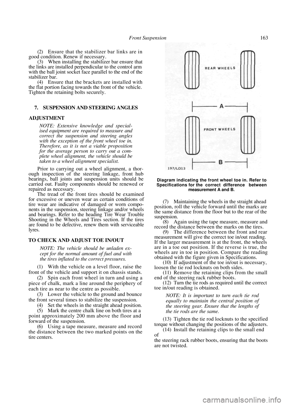
(1) With the vehicle on a level floor, raise the
front of the vehicle and s upport it on chassis stands.
(2) Spin each front wheel in turn and using a
piece of chalk, mark a line around the periphery of
each tire as near to the centre as possible. (3) Lower the vehicle to the ground and bounce
the front several times to stabilize the suspension. (4) Set the wheels in the straight ahead position.
(5) Mark the centre chalk line on both tires at a
point approximately 200 mm above the floor and
forward of the suspension. (6) Using a tape measure, measure and record
the distance between the two marked points on the
tire centers.
Diagram indicating the front wheel toe in. Refer to
Specifications for the correct difference between
measurement A and B.
(7) Maintaining the wheels in the straight ahead
position, roll the vehicle forward until the marks are
the same distance from the floor but to the rear of the
suspension. (8) Again using the tape measure, measure and
record the distance between the marks on the tires.
(9) The difference between the front and rear
measurement will give the correct toe in/out reading.
If the larger measurement is at the front, the wheels
are in a toe out position. If the reverse is true, the
wheels are in toe in position. Compare the reading
obtained with the figure given in Specifications.
(10) If adjustment of the to e in/out is necessary,
loosen the tie rod locknuts on both sides. (11) Remove the retaining clips from the small
end of the steering rack rubber boots. (12) Turn the tie rods as required until the correct
toe in/out reading is obtained.
NOTE: It is important to turn each tie rod
equally to maintain the central position of
the steering gear. Ensure that the lengths of
the tie rods are the same.
(13) Tighten the tie rod locknuts to the specified
torque without changing the positions of the adjusters.
(14) Install the retaining clips to the small end
of
the steering rack rubber boots, ensuring that the boots
are not twisted.
Page 164 of 238
164
REAR SUSPENSION
SPECIFICATIONS
Type........................... Independent MacPherson strut
Shock absorber.................... Oil filled, non-repairable
Maximum hub bearing end float ................. 0.05 mm
Rear wheel alignment:
Toe out ........................................3 mm ± 2 mm
Camber ............................................. - 1 ° ± 4 5 '
TORQUE WRENCH SETTINGS
Hub retaining nut ......................................... 255 Nm
Suspension unit retaining nuts ....................... 29 Nm
Upper mounting retaining nut ........................ 72 Nm
Suspension unit to knuckle nuts .................. 118 Nm
Control arms to knuckle nut ........................ 118 Nm
Control arms to crossmember nut ............... 118 Nm
Stabiliser bar mounting bracket bolts .......... 108 Nm
Stabiliser bar retaining nut.............................. 83 Nm
Backing plate bolts........................................... 45 Nm
1. REAR SUSPENSION TROUBLE SHOOTING
REAR END NOISE
( 1 ) Defective suspension unit or mounting: Re-
new the faulty components.
(2) Loose or worn control arm bushes or pivot
bolts: Check and tighten or renew the worn compo-
nents. (3) Broken coil spring: Renew the coil spring,
preferably in matching pairs. (4) Worn rear hub bearing: Check and renew the
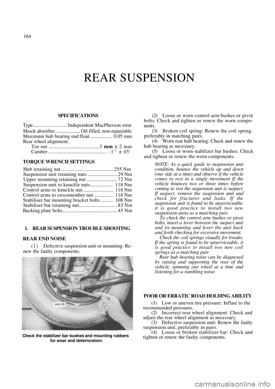
hub bearing as necessary. (5) Loose or worn stabilizer bar bushes: Check
and tighten or renew the worn components.
NOTE: As a quick guide to suspension unit
condition, bounce the vehicle up and down
(one side at a time) and observe if the vehicle
comes to rest in a single movement If the
vehicle bounces two or three times before
coming to rest the susp ension unit is suspect.
If suspect, remove the suspension unit and
check for fractures and leaks. If the
suspension unit is found to be unserviceable,
it is good practice to install two new
suspension units as a matching pair.
To check the control arm bushes or pivot
bolts, insert a lever between the suspect unit
and its mounting and lever the unit back
and forth checking for excessive movement.
Check the coil springs visually for breaks.
If the spring is found to be unserviceable, it
is good practice to install two new coil
springs as a matching pair.
Rear hub bearing noise can be diagnosed
by raising and supporting the rear of the
vehicle, spinning one wheel at a time and
listening for a rumbling noise.
POOR OR ERRATIC ROAD HOLDING ABILITY
(1) Low or uneven tire pressure: Inflate to the
recommended pressures.
(2) Incorrect rear wheel alignment: Check and
adjust the rear wheel alignment as necessary.
(3) Defective suspension unit: Renew the faulty
suspension unit, preferably in pairs. (4) Loose or broken stabilizer bar: Check and
tighten or renew the faulty components.
Check the stabilizer bar bushes and mounting rubbers
for wear and deterioration.
Page 166 of 238
166 Rear Suspension
3. REAR HUB
Special Equipment Required
To Check Hub Bearing End Float — Dial gauge
To Renew Bearing — Press and suitable drift
TO REMOVE AND INSTAL
(1) Raise the rear of the vehicle and support it
on chassis stands. Remove the rear wheel and release
the handbrake.
(2) On models with rear drum brakes, proceed
to operation (6).
(3) Remove the clip securing the brake hose to
the suspension unit and disengage the hose.
(4) Remove the bolts securing the brake caliper
to the knuckle assembly. (5) Slide the caliper from the disc and support it
away from the working area, ensuring that no excess
strain is placed on the brake hose. (6) Rotate the hub and check that it rotates
smoothly. If it does not rotate smoothly, renew the
hub bearing. (7) Mount a dial gauge with the plunger posi-
tioned against the outer face of the hub. Move the hub
back and forth in line with the stub axle and note the
reading on the dial gauge. If the end float exceeds
Specifications, renew the hub bearing.
(8) Remove the hub grease cap from the rear
hub. (9) Remove the split pin from the stub axle and
remove the nut retainer, the hub retaining nut and
washer. Remove the hub assembly from the stub axle. Installation is a reversal of the removal procedure
with attention to the following points:
(1) Tighten the hub retaining nut to the specified
torque. (2) Check the hub bearing end float as previ-
ously described.
(3) On models with disc brakes, install the brake
caliper and tighten the retaining bolts to the torque
specified in the Brakes section. Install the brake hose to
the suspension unit and secure with the retaining clip.
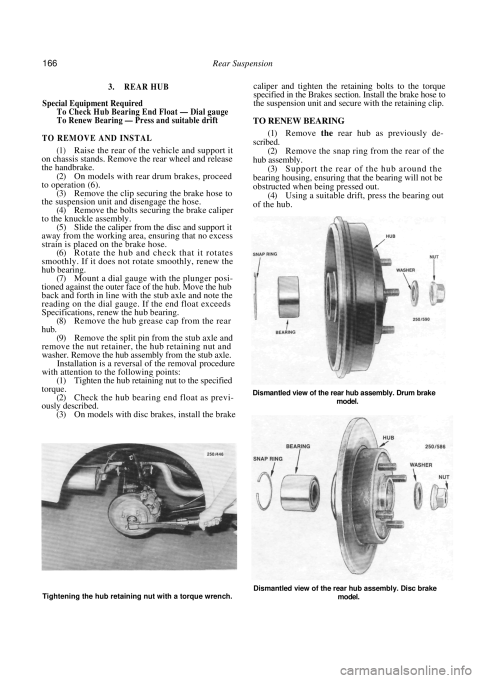
TO RENEW BEARING
(1) Remove the rear hub as previously de-
scribed. (2) Remove the snap ring from the rear of the
hub assembly. (3) Support the rear of the hub around the
bearing housing, ensuring that the bearing will not be
obstructed when being pressed out. (4) Using a suitable drift, press the bearing out
of the hub.
Dismantled view of the rear hub assembly. Drum brake
model.
Tightening the hub retaining nut with a torque wrench. Dismantled view of the rear hub assembly. Disc brake
model.
Page 168 of 238
168 Rear Suspension
NOTE: If a coil spring is defective it is
advisable to renew both coil springs as a
matched set.
(13) Check the spring seat for cracks, deforma-
tion or wear and renew as necessary.
(14) Check the upper mounting and the insulator
for wear, damage, signs of melting rubber or deterio-
ration. (15) Check that the piston rod is not cracked,
bent or damaged.
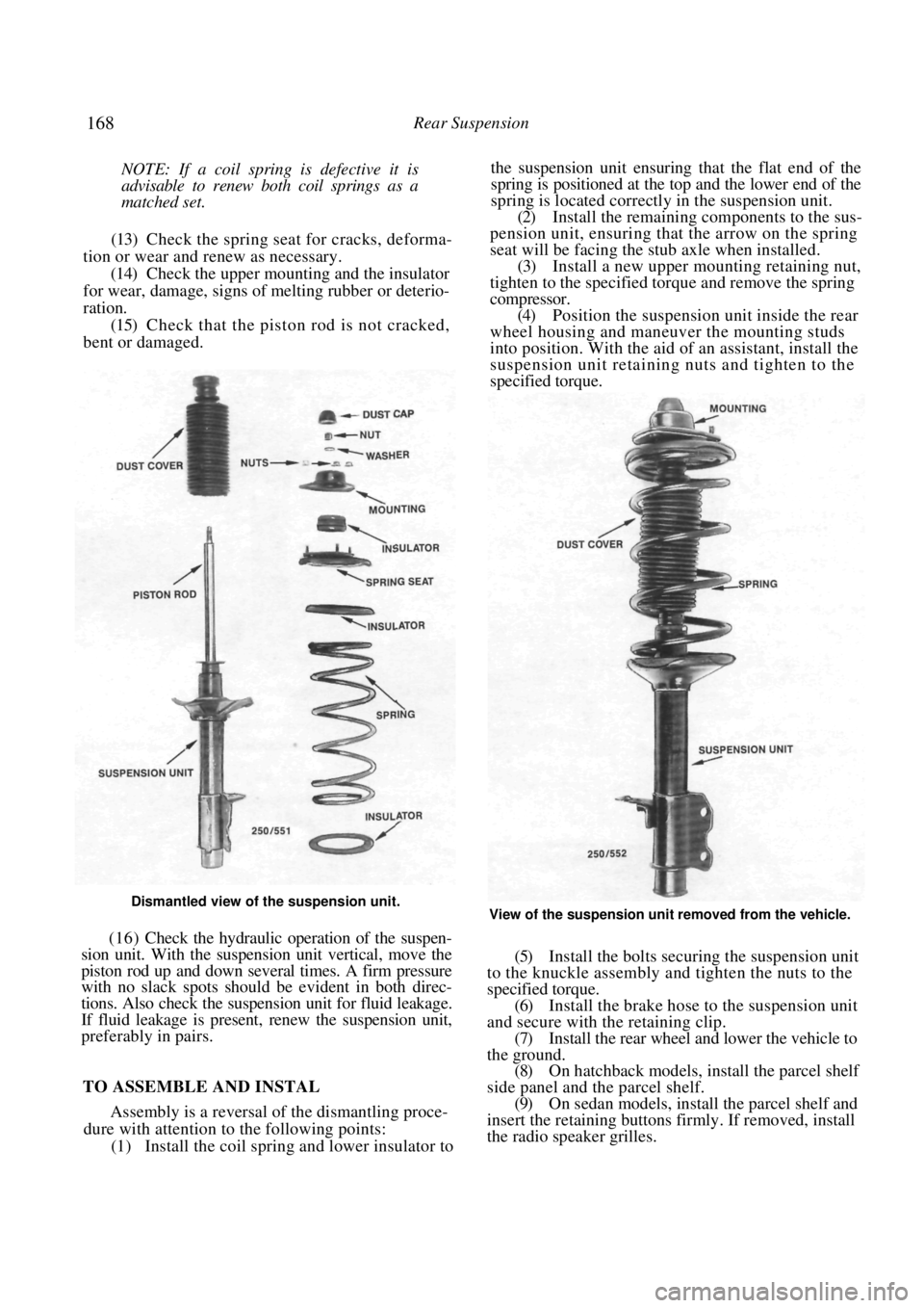
Dismantled view of the suspension unit.
(16 ) Check the hydraulic operation of the suspen-
sion unit. With the suspension unit vertical, move the
piston rod up and down severa l times. A firm pressure
with no slack spots should be evident in both direc-
tions. Also check the suspen sion unit for fluid leakage.
If fluid leakage is present, renew the suspension unit,
preferably in pairs.
TO ASSEMBLE AND INSTAL
Assembly is a reversal of the dismantling proce-
dure with attention to the following points:
(1) Install the coil spring and lower insulator to
the suspension unit ensuring th at the flat end of the
spring is positioned at the top and the lower end of the
spring is located correctly in the suspension unit.
(2) Install the remaining co mponents to the sus-
pension unit, ensuring that the arrow on the spring
seat will be facing the stub axle when installed.
(3) Install a new upper mounting retaining nut,
tighten to the specified tor que and remove the spring
compressor. (4) Position the suspension unit inside the rear
wheel housing and maneuver the mounting studs
into position. With the aid of an assistant, install the
suspension unit retaining nuts and tighten to the
specified torque.
View of the suspension unit removed from the vehicle.
(5) Install the bolts securin g the suspension unit
to the knuckle assembly and tighten the nuts to the
specified torque.
(6) Install the brake hose to the suspension unit
and secure with the retaining clip. (7) Install the rear wheel and lower the vehicle to
the ground. (8) On hatchback models, install the parcel shelf
side panel and the parcel shelf. (9) On sedan models, install the parcel shelf and
insert the retaining buttons firmly. If removed, install
the radio speaker grilles.