engine coolant NISSAN PULSAR 1987 Owner's Manual
[x] Cancel search | Manufacturer: NISSAN, Model Year: 1987, Model line: PULSAR, Model: NISSAN PULSAR 1987Pages: 238, PDF Size: 28.91 MB
Page 84 of 238
Fuel and Engine Management
(4) MAP sensor faulty or supply hose discon-
nected or blocked: Check the vacuum supply hose.
Check the operation of the MAP sensor.
EXCESSIVE FUEL CONSUMPTION
(1) Blocked air cleaner element: Check the ele-
ment and clean or renew as necessary.
(2) Incorrect fuel pressure: Check the fuel pump
and fuel pressure regulator. (3) Faulty coolant temperature sensor: Check
the connections and operation.
(4) Leaks in the fuel supply system: Check the
connections and components for leakage. (5) Leaking fuel injector(s): Clean or renew the
faulty injector(s). (6) Engine operating temperature too low:
Check the thermostat and electric cooling fan as
described in the Cooling an d Heating Systems section.
2. DESCRIPTION
The engine management system on the range of
vehicles covered by this manual controls the opera-
tion of the ignition system and the fuel system.
The central component of the engine management
system is the electronic control unit (ECU). The con-
trol unit is a micro-computer which controls the igni-
tion timing and the amount of fuel injected according
to signals received from various sensors. As changes
are detected in engine load and speed, coolant tem-
perature, barometric pressure, air temperature (1.8
liter engine), throttle position and vehicle speed, the
control unit alters the ignition timing and the fuel
injection amount to achieve optimum engine effi-
ciency.
The control unit incorporates a self diagnosis
mode which stores and displays codes relating to
certain system malfunctions. Whenever power is sup-
plied to the control unit, the control unit performs a
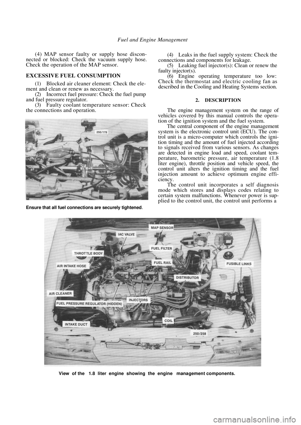
View of the 1.8 liter engine showing the engine management components.
Ensure that all fuel connections are securely tightened.
Page 90 of 238
90 Fuel and Engine Management
To identify the code number, count the number of
times the ECM warning lamp flashes. Each fault code
comprises two groups of flashes separated by a 1.2
second pause. The first group represents tens and the
second group represents single units. For example 1
flash followed by a 1.2 second pause followed by 4
flashes would be code number 14. Similarly 4 flashes
followed by a 1.2 second pause followed by 2 flashes
would be code number 42.
The code will be displayed three times. If more
than one fault code is present, the self diagnosis
system will indicate each one in numerical order, with
a 3.2 second pause between each code, and then
repeat the sequence.
The fault codes can be identified as follows:
CODE NUMBER FAULT AREA
12 Satisfactory operation
13 Oxygen sensor open circuit
14 Coolant temperature sensor circuit (voltage low)
15 Coolant temperature sensor circuit (voltage high)
21 Throttle position sensor circuit (voltage high)
22Throttle position sensor circuit (voltage low)
23MAT sensor circuit (voltage' high) 1.8 liter engine
only
24 Vehicle speed sensor circuit
25 MAT sensor circuit
(voltage low) 1.8 liter engine
only
33 MAP sensor circuit
(voltage high)
34MAP sensor circuit (voltage low)
42 Electronic spark timing circuit
44
Oxygen sensor circuit
(lean exhaust)
45Oxygen sensor circuit (rich exhaust)
51 Mem-Cal
55 Control unit input circuits
Test Procedure
(1) Perform the following checks:
(a) Ensure that the battery voltage is above 11
volts. (b) Ensure that the throttle valve is fully closed.
(c) Place the transaxle in neutral.
(d) Ensure that the air conditioner, fan, tights
and all other accessories are switched off.
(2) Turn the ignition On and confirm that the
ECM warning lamp on the instrument cluster is
illuminated but not flashing.
If code 55 is displayed, refer to the Control Unit
heading, perform the circuit test procedure and rectify
the cause of the code before proceeding.
If the ECM warning lamp flashes codes other than
code 55, check the wiring harness between the diag-
nostic link connector terminal B and the control unit
wiring connector terminal A9 for shorts. Repair or
renew the wiring harness as necessary.
If no fault can be found, renew the control unit.
If the ECM warning lamp does not illuminate,
proceed as follows:
(a) Check the METER fuse located in the fuse
panel adjacent to the steering column and the fusible
links located in the fusible link connecting block at the
rear of the battery. Renew the fuse or fusible links as
necessary. (b) Check the wiring harness to the instrument
cluster. Repair or renew the harness. (c) Check the Check Engine lamp bulb. Renew if
necessary. (d) Check the EGI relay. Renew as necessary.
(3) Connect a jumper lead across terminals A
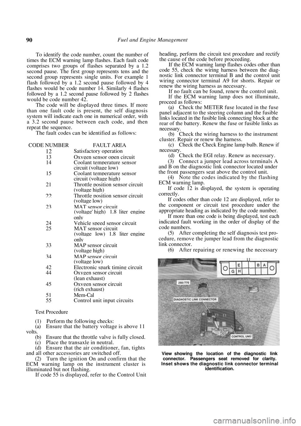
and B on the diagnostic link connector located under
the front passengers seat above the control unit.
(4) Note the codes indicated by the flashing
ECM warning lamp.
If code 12 is displayed, the system is operating
correctly.
If codes other than code 12 are displayed, refer to
the component or circuit test procedure under the
appropriate heading as indicated by the code number.
If more than one code is being displayed, test each
indicated fault working in the order of display of the
code numbers.
(5) After completing the self diagnosis test pro-
cedure, remove the jumper lead from the diagnostic
link connector. (6) After repairing or renewing the necessary
View showing the location of the diagnostic link
connector. Passengers seat removed for clarity.
Inset shows the diagnostic link connector terminal identification.
Page 101 of 238
Fuel and Engine Management 101
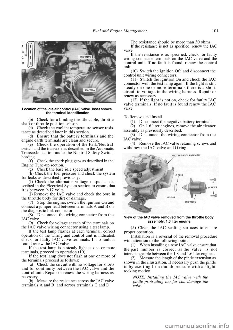
Location of the idle air control (IAC) valve. Inset shows the terminal identification.
(b) Check for a binding throttle cable, throttle
shaft or throttle position sensor. (c) Check the coolant temperature sensor resis-
tance as described later in this section. (d) Ensure that the battery terminals and the
engine earth terminals are clean and secure.
(e) Check the operation of the Park/Neutral
switch and the transaxle as described in the Automatic
Transaxle section under the Neutral Safety Switch
heading. (f) Check the spark plug gaps as described in the
Engine Tune-up section.
(g) Check the base idle speed adjustment.
(h) Check the fuel pressure and check the system
for leaks as described previously.
(I) Check the alternator voltage output as de-
scribed in the Electrical System section to ensure that
it is between 9-17 volts.
(j) Remove the IAC valve and check the bore in
the throttle body for dirt or damage.
(7) Stop the engine, switch the ignition On and
connect a jumper lead between terminals A and B on
the diagnostic link connector. (8) Disconnect the wiring connector from the
IAC valve.
(9) Check for voltage at each of the terminals on
the IAC valve wiring connector using a test lamp. If the test lamp flashes at each terminal, correct
operation of the wiring and control unit is indicated.
check for faulty IAC valve terminals. If no fault is
found renew the IAC valve.
If the test lamp is a steady light at one or more
terminals, proceed to operation (10).
If the test lamp does not flash at one or more of
the terminals proceed as follows:
(a) Check the circuit with no voltage for shorts
and for continuity between the IAC valve and the
control unit. Repair or renew the wiring harness as
necessary.
(b) Measure the resistance across the IAC valve
terminals A and B, and across terminals C and D. The resistance should be more than 30 ohms.
If the resistance is not as specified, renew the IAC
valve.
If the resistance is as specified, check for faulty
wiring connector terminals on the IAC valve and the
control unit. If no fault is found, renew the control
unit
(10) Switch the ignition Oft' and disconnect the
control unit wiring connectors. (11) Switch the ignition On and check the IAC
connector with the test lamp again. If the light is stilt
steady on one or more terminals there is a short
circuit to voltage in the wiring harness. Repair or
renew as necessary. (12) If the light is not on, check for faulty IAC
valve terminals. If no fault is found renew the IAC
valve.
To Remove and Install
(1) Disconnect the negative battery terminal.
(2) On 1.6 liter engines, remove the air cleaner
assembly as previously described. (3) Disconnect the wiring connector from the
IAC valve. (4) Remove the IAC valve retaining screws and
withdraw the IAC valve and O ring.
View of the IAC valve removed from the throttle body
assembly. 1.6 liter engine.
(5) Clean the IAC sealing surfaces to ensure
proper operation.
Installation is a reversal of the removal procedure
with attention to the following points:
(1) When installing a new IAC valve ensure that
the part number is correct as the valve is not
interchangeable between the 1.8 and 1.6 liter engines.
(2) Measure the length of the pintle extension as
shown in the illustration. If necessary push the pintle
in by exerting firm thum b pressure with a slight
rocking motion.
NOTE: Installing (he IAC valve with the
pintle protruding too far can damage the
valve.
Page 109 of 238
Fuel and Engine Management 109
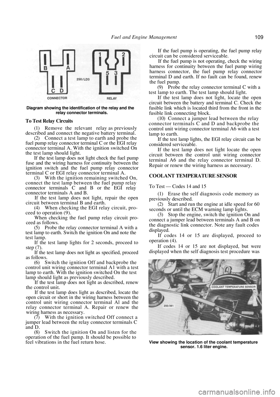
Diagram showing the identification of the relay and the relay connector terminals.
To Test Relay Circuits
(1) Remove the relevant relay as previously
described and connect the ne gative battery terminal.
(2) Connect a test lamp to earth and probe the
fuel pump relay connector terminal C or the EGI relay
connector terminal A. With the ignition switched On
the test lamp should light. If the test lamp does not light check the fuel pump
fuse and the wiring harness for continuity between the
ignition switch and the fuel pump relay connector
terminal C or EGI rela y connector terminal A.
(3) With the ignition remaining switched On,
connect the test lamp between the fuel pump relay
connector terminals C and B or the EGI relay
connector terminals A and B.
If the test lamp does not light, repair the open
circuit between terminal B and earth.
(4) When checking the EGI relay circuit, pro-
ceed to operation (9).
When checking the fuel pu mp relay circuit pro-
ceed as follows.
(5) Probe the relay connector terminal A with a
test lamp to earth. Switch the ignition On and note the
test lamp.
If the test lamp lights for 2 seconds, proceed to
step (7).
If the test lamp does not light as specified, proceed
as follows.
(6) Switch the ignition Off and backprobe the
control unit wiring connector terminal A1 with a test
lamp to earth. With the ignition switched On the test
lamp should light as previously described.
If the test lamp does not light as described, renew
the control unit.
If the test lamp does light as described, locate the
open circuit or short in the wiring harness between the
control unit wiring connector terminal Al and the
relay connector terminal A. Repair or renew the
wiring harness as necessary.
(7) With the ignition switched Off connect a
jumper lead between the relay connector terminals C
and D. (8) Switch the ignition On and listen for the
operation of the fuel pump. It should be possible to
feel vibrations in the fuel return hose. If the fuel pump is operating, the fuel pump relay
circuit can be considered serviceable.
If the fuel pump is not operating, check the wiring
harness for continuity between the fuel pump wiring
harness connector, the fuel pump relay connector
terminal D and earth. If no fault can be found, renew
the fuel pump.
(9) Probe the relay connector terminal C with a
test lamp to earth. The test lamp should light.
If the test lamp does not light, locate the open
circuit between the battery and terminal C. Check the
fusible link which is located third from the front in the
fusible link connecting block.
(10) Connect a jumper lead between the relay
connector terminals C and D and backprobe the
control unit wiring connector terminal A6 with a test
lamp to earth.
If the test lamp lights, the EGI relay circuit can be
considered serviceable.
If the test lamp does not light locate the open
circuit between the contro l unit wiring connector
terminal A6 and the relay connector terminal D.
Repair or renew the wiring harness as necessary.
COOLANT TEMPERATURE SENSOR
To Test — Codes 14 and 15
(1) Erase the self diagnosis code memory as
previously described. (2) Start and run the engine at idle speed for 60
seconds or until the ECM warning lamp lights.
(3) Stop the engine, switch the ignition On and
connect a jumper lead between terminals A and B on
the diagnostic link connect or. Note any fault codes
displayed. If codes 14 or 15 are displayed, proceed to
operation (4).
If codes 14 or 15 are not displayed, but were
displayed when the self diagnosis test procedure was
View showing the location of the coolant temperature
sensor. 1.6 liter engine.
Page 110 of 238

110 Fuel and Engine Management
originally performed, an intermittent fault is indi-
cated. Proceed as follows:
(a) Check for faulty wiri ng connections. Check
that all wiring connectors are clean and secure. (b) Check that all earth wires are secure.
(4) Disconnect the wiring connector from the
coolant temperature sensor. (5) With the ignition switched On, measure the
voltage across the terminals on the coolant tempera-
ture sensor wiring connector. The voltage should be
4-6 volts.
If the voltage is below 4 volts, proceed to opera-
tion (9).
If the voltage is as specified, proceed as follows.
(6) Remove the coolant temperature sensor
from the vehicle. (7) Connect an ohmmeter to the coolant temper-
ature sensor terminals. (8) Immerse the meta1 end of the coolant
tem-
perature sensor in a 50/50 mixture of glycol and iced
water at a temperature of 0 deg C. The resistance
should be 6 000 ohms. Slowly heat the mixture and measure the resis-
tance of the coolant temperature sensor at the follow-
ing temperatures. Compare the results with the spec-
ified values:
0 d e g C ................................................. 6 000 ohms
20 deg C .................................................. 2 500 ohms
30 deg C .................................................. 1 800 ohms
40 deg C.................................................. 1 200 ohms
70 deg C .......................................................450 ohms
90 degC .......................................................250 ohms
100 deg C.....................................................190 ohms
110 deg C.....................................................110 ohms
If the resistances obtained are not as specified at
any of the given temperatures, renew the coolant
temperature sensor and retest for fault codes.
(9) Disconnect the control unit wiring connec-
tors.
(10) Check the wiring harness for shorts and
continuity between the coolant temperature sensor
wiring connector terminals and the control unit wiring
connector terminals C10 and D2. Repair or renew the
wiring harness as necessary.
Also check the control unit terminals for damage.
If no fault is found, renew the control unit and
retest for fault codes.
To Remove and Install
(1) Disconnect the negative battery terminal.
(2) Disconnect the wiring connector from the
coolant temperature sensor.
(3) Drain the coolant as described in the Cooling
and Heating Systems section to a level below the
sensor.
(4) Unscrew the sensor from the thermostat
housing. Installation is a reversal of the removal procedure
with attention to the following points;
(1) Apply Loctite 675 or a similar conductive
sealer to the threads of th e sensor. Tighten the sensor
to the specified torque.
(2) Fill the cooling system with the correct
mixture of water and inhibitor as described in the
Cooling and Heating Systems section. (3) Ensure that the wiring connector is clean and
secure.
THROTTLE POSITION SENSOR
To Test - Codes 21 and 22
NOTE: The following test procedure as-
sumes that fault codes 21 or 22 have been
displayed during the se lf diagnosis test pro-
cedure. If no codes have been displayed but
the operation of the throttle position sensor
is suspect, begin the test procedure at oper-
ation (24).
(1) Erase the self diagnosis code memory as
previously described.
(2) Start and run the engine at idle speed for 60
seconds or until the ECM warning lamp lights. If the engine will not start, disconnect the throttle
position sensor wiring co nnector and proceed to
operation (8). .
(3) With the engine id ling, quickly increase the
engine speed to 3 000 rpm and return to idle.
If the ECM warning lamp remains illuminated,
proceed to operation (4).
If the ECM warning lamp extinguishes, an inter-
mittent fault is indicated. Proceed as follows:
(a) Check for faulty wiri ng connections. Check
that all wiring connectors are clean and secure. (b) Check that all earth wires are secure.
(4) Stop the engine, switch the ignition On and
connect a jumper lead between terminals A and B on
the diagnostic link connect or. Note any fault codes
displayed.
If codes 21 or 22 are displayed, proceed as
follows.
(5) Remove the jumper lead from the diagnostic
link connector. (6) Erase the self diagnosis codes as previously
described. (7) Disconnect the wiring connector from the
throttle position sensor. If code 22 was displayed in operation (4), proceed
to operation (13).
If code 21 was displayed in operation (4), proceed
as follows.
(8) Start and run the engine at idle speed for 2
minutes or until the ECM warning lamp lights. If the
engine will not start, pr oceed to operation (11).
(9) Stop the engine, switch the ignition On and
connect a jumper lead between terminals A and B on
Page 114 of 238

114 Fuel and Engine Management
(6) Check the vehicle for the following:
(a) Low fuel pressure.
(b) Contaminated fuel.
(c) Vacuum leaks at the inlet manifold, engine
vacuum hoses and engine ventilation hoses. (d) Exhaust manifold leaks before the oxygen
sensor. (e) Correct MAP sensor operation.
(f) Blocked oxygen sensor metal vent cover eg.
plugged with mud etc. (g) Fuel injectors) partially blocked. Refer to a
fuel injection specialis t or a Nissan dealer.
If the above items have been checked and no
faults have been found, a faulty oxygen sensor is
indicated. Renew the oxygen sensor, run the engine
and ensure that no fault codes are set.
To Test — Code 45
(1) Run the engine until normal operating tem-
perature is attained. (2) With the ignition switched Off, connect a
jumper lead between terminals B and A on the
diagnostic link connector. (3) Start and run the engine at approximately
1 600-1 800 rpm for 2 minutes and note the ECM
warning lamp. If the ECM warning lamp is on more than off or
flashes at the rate of twice per second, proceed to the
following operation.
If the ECM warning lamp flashes evenly at the
rate of once per second an intermittent fault is
indicated. Proceed as follows:
(a) Check for faulty wiri ng connections. Check
that all wiring connectors are clean and secure. (b) Check that all earth wires are secure.
(4) Switch the engine Off and disconnect the
oxygen sensor wiring connector. (5) Using a jumper lead, connect the oxygen
sensor wiring connector to a suitable engine earth. (6) Start and run the engine at 1 600-1 800 rpm
and note the ECM warning lamp.
If the ECM warning lamp extinguishes for at least
30 seconds, proceed to operation (7).
If the ECM warning lamp flashes on more than off
or flashes at the rate of twice per second, switch the
engine Off and disconnect the control unit wiring
connectors. Using an ohmmeter, check that there is no
resistance between the co ntrol unit wiring connector
terminal D6 and earth. Repair or renew the wiring as
necessary.
If no fault can be found in the wiring harness,
renew the control unit.
NOTE: The wiring harness for terminal D6
earths through the righ t hand rear cylinder
head bolt.
(7) Check the vehicl e for the following:
(a) High fuel pressure.
(b) Leaking injector(s).
(c) Faulty ignition wiring.
(d) Charcoal canister purge system blocked or
restricted.
(e) Faulty coolant temper ature sensor circuit.
(f) Faulty MAT sensor circuit (1.8 liter engine).
(g) MAP sensor operation.
(h) Throttle position sensor operation.
If the above items have been checked and no
faults have been found, a faulty oxygen sensor is
indicated.
Renew the oxygen sensor, run the engine and
ensure that no fault codes are set.
To Remove and Install
(1) If the engine is cold, run the engine for
approximately two minutes to allow easy oxygen
sensor removal. (2) Disconnect the negative battery terminal and
the oxygen sensor connector.
View of the oxygen sensor removed from the exhaust
manifold.
(3) Remove the exhaust manifold heat shield
retaining bolts and remove the heat shield from the
engine.
(4) Remove the oxygen sensor with a short ring
spanner using care not to damage the sensor wire. Installation is a reversal of the removal procedure
with attention to the following points:
(1) When installing a sensor that has previously
been removed, coat the sen sor threads with anti-seize
compound. Nissan recommend a mixture of liquid
graphite and glass beads. (2) Install the sensor and tighten to the specified
torque. (3) Connect the electrical connector ensuring
that the wiring is secured away from the exhaust. (4) Install the heat shield and tighten the retain-
ing bolts securely. On 1.6 liter engines, ensure that the hot air inlet
tube is located correctly be tween the heat shield and
the air cleaner housing.
(5) Start the engine and check for leaks.
VEHICLE SPEED SENSOR
To Test - Code 24
(1) Check the fuel pump and meter fuses. If the
fuses are serviceable, proceed to operation (5). If a
fuse is blown, rectify the cause and renew the fuse.
Page 197 of 238
Electrical System 197
Switch on all lamps and allow them to
illuminate for approximately five minutes to reduce
the charge of the battery and to apply a load to the
circuit.
Start the engine and gradually increase the
speed to approximately 2 500 rpm. The reading on
the ammeter should be approximately 75% of the
rated output of the altern ator. See Specifications.
Switch off all the lamps and run the engine at
1 500-2 000 rpm until the indicated charge is below
10 amps. The voltmeter should now read in excess of
13.6 volts.
NOTE: Should the alternator fail to reach
the specific output, the unit will have to be
removed and overhauled or a replacement
unit installed.
Should the voltage reading be above or
below Specifications, the regulator will have
to be renewed.
TO REMOVE AND INSTAL
Disconnect the negative battery terminal.
On 1.8 liter engines, remove the bolt secur-
ing the air cleaner intake duct and remove the air
cleaner intake duct. Drain the radiator by releasing the radiator
drain plug, located at the bottom of the radiator and
allow the coolant level to fall below the thermostat
housing level. NOTE: Refer to the Cooling and Heating
Systems section when refilling the radiator
coolant to its correct l
evel, failure to do so
could result in severe damage to engine
components.
Remove the retaining bolts securing the
thermostat housing, disconnect the hose from the
radiator and remove the thermostat housing and
radiator hose from the vehicle. Using a socket and extension bar, remove the
bolt securing the alternator to the drive belt tensioning
bar located under the alternator. On vehicles not equipped with air condition-
ing, remove the front splash guard from under the
front of the vehicle and remove the bolt securing the
alternator to the drive belt tensioning bar. Loosen the upper mounting bolts, slacken
the alternator drive belt and remove it from the
alternator pulley.
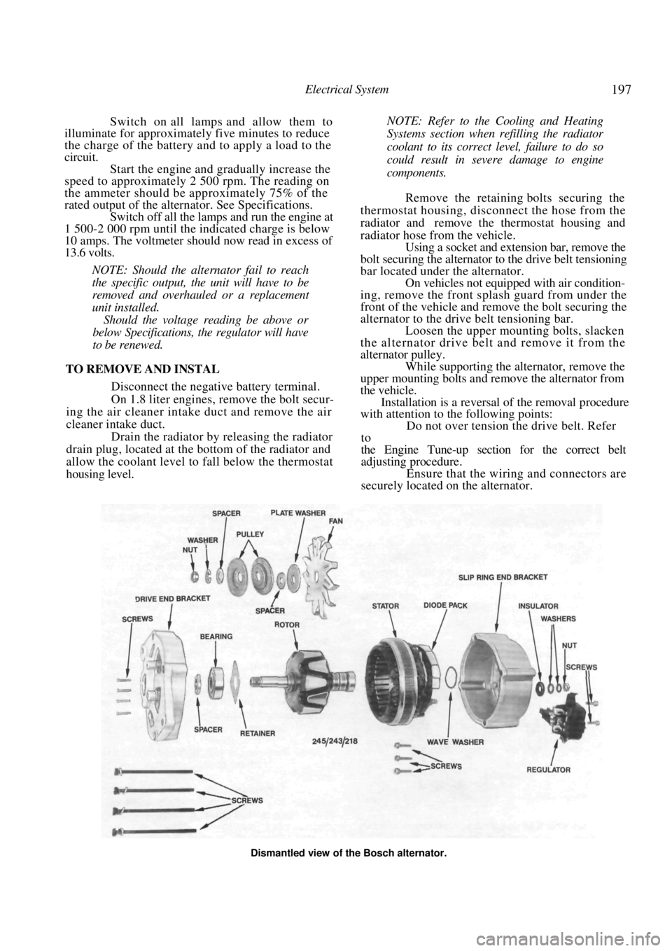
While supporting the alternator, remove the
upper mounting bolts and remove the alternator from
the vehicle. Installation is a reversal of the removal procedure
with attention to the following points:
Do not over tension the drive belt. Refer
to
the Engine Tune-up section for the correct belt
adjusting procedure. Ensure that the wiring and connectors are
securely located on the alternator.
Dismantled view of the Bosch alternator.