rocker NISSAN PULSAR 1987 Workshop Manual
[x] Cancel search | Manufacturer: NISSAN, Model Year: 1987, Model line: PULSAR, Model: NISSAN PULSAR 1987Pages: 238, PDF Size: 28.91 MB
Page 3 of 238
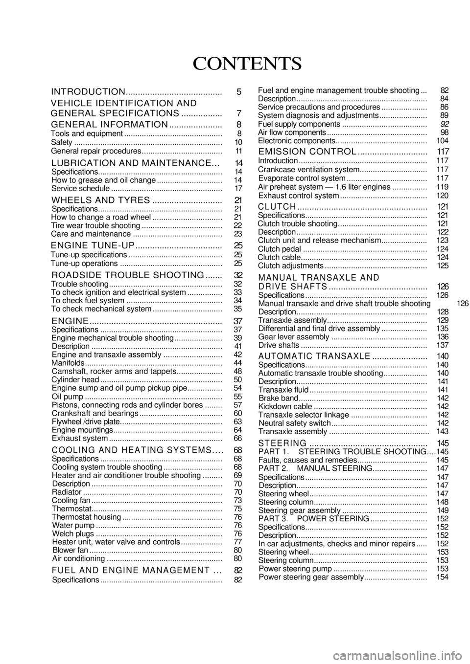
CONTENTS
INTRODUCTION........................................ 5
VEHICLE IDENTIFICATION AND
GENERAL SPECIFICATIONS................. 7
GENERAL INFORMATION...................... 8
Tools and equipment ............................................. 8 Safety .................................................................... 10
General repair procedures..................................... 11
LUBRICATION AND MAINTENANCE... 14
Specifications......................................................... 14
How to grease and oil change .............................. 14
Service schedule ................................................... 17
WHEELS AND TYRES............................. 21
Specifications......................................................... 21
How to change a road wheel ................................ 21
Tire wear troubl e shooting ..................................... 22
Care and main tenance ......................................... 23
ENGINE TUNE-UP.................................... 25
Tune-up specifications ........................................... 25
Tune-up operat ions............................................... 25
ROADSIDE TROUBLE SHOOTING....... 32
Trouble shoot ing.................................................... 32
To check ignition and el ectrical system ................ 33
To check fuel system ............................................ 34
To check mechani cal system ................................ 35
ENGINE....................................................... 37
Specifications ........................................................ 37
Engine mechanical tr ouble shooting ...................... 39
Description ............................................................ 41
Engine and transaxle assembly ........................... 42
Manifolds ............................................................... 44 Camshaft, rocker arms and tappets..................... 48
Cylinder head........................................................ 50
Engine sump and oil pum p pickup pipe................ 54
Oil pump ............................................................... 55
Pistons, connecting rods and cylinder bores ........ 57
Crankshaft and bearings ...................................... 60
Flywheel /drive plate............................................... 63
Engine mountings.................................................. 64
Exhaust system .................................................... 66
COOLING AND HEATING SYSTEMS.... 68
Specifications ........................................................ 68 Cooling system trouble shooting ........................... 68
Heater and air conditioner trouble shooting ......... 69 Description ............................................................ 70
Radiator ................................................................ 70
Cooling fan ............................................................ 73
Thermost at............................................................ 75
Thermostat housing .............................................. 76
Water pump .......................................................... 76
Welch plugs .......................................................... 76
Heater unit, water valv e and controls ................... 77
Blower fan ............................................................. 80
Air condition ing ..................................................... 80
FUEL AND ENGINE MANAGEMENT ... 82
Specifications ........................................................ 82 Fuel and engine management trouble shooting ... 82
Description ............................................................ 84
Service precautions and procedures
..................... 86
System diagnosis and adjustments ...................... 89
Fuel supply components ....................................... 92
Air flow components .............................................. 98
Electronic components .......................................... 104
EMISSION CONTROL............................. 117
Introduction ........................................................... 117
Crankcase ventilati on system............................... 117
Evaporate control system..................................... 117
Air preheat system — 1.6 liter engines ................ 119
Exhaust control system ........................................ 120
CLUTCH...................................................... 121
Specifications........................................................ 121
Clutch trouble shooting......................................... 121
Description ............................................................ 122
Clutch unit and release mechanism..................... 123
Clutch pedal ......................................................... 124
Clutch c able.......................................................... 124
Clutch adjustments ............................................... 125
MANUAL TRANSAXLE AND
DRIVE SHAFTS......................................... 126
Specifications ........................................................ 126
Manual transaxle and drive shaft trouble shooting 126
Description............................................................ 128
Transaxle assembly.............................................. 129
Differential and final drive assembly ..................... 135
Gear lever assembly ............................................ 136
Drive shafts .......................................................... 137
AUTOMATIC TRANSAXLE....................... 140
Specifications........................................................ 140
Automatic transaxle trouble shooting.................... 140
Description............................................................ 141
Transaxle fluid ...................................................... 141
Brake band........................................................... 142
Kickdown cable .................................................... 142
Transaxle select or linkage ................................... 142
Neutral safety switch ............................................ 142
Transaxle assembly .............................................. 143
STEERING................................................. 145
PART 1. STEERING TROUBLE SHOOTING....145
Faults, causes and remedies................................ 145
PART 2. MANUA L STEERING......................... 147
Specifications ........................................................ 147
Description............................................................ 147
Steering wheel ...................................................... 147
Steering column.................................................... 148
Steering gear assembly ....................................... 149
PART 3. POWE R STEERING .......................... 152
Specifications........................................................ 152
Description............................................................ 152
In car adjustments, checks and minor repairs ..... 152
Steering wheel ...................................................... 153
Steering column.................................................... 153 Power steering pump ........................................... 153
Power steering gear assembly............................. 154
Page 39 of 238
Engine 39
Oil pump cover plate screws............................ 6 Nm
Oil pump mounting bolts.................................. 6 Nm
Oil pump pickup bolts
(coat with Loctite 242)..................................... 8 Nm
Sump bolts (coat with Loctite 242) .................. 5 Nm
Sump drain plug .............................................. 35 Nm
*Use new bolts
Head bolts maximum torque 135 Nm
1. ENGINE MECHANICAL TROUBLE
SHOOTING
ENGINE MISSES AT IDLING SPEED
NOTE: For other causes of engine misfire,
refer to the Fuel and Engine Management
section.
(1) Blown head gasket: Check the cylinder com-
pressions and renew the he ad gasket as necessary.
(2) Burnt valves or seats in the cylinder head:
Check the cylinder compressions and overhaul the
cylinder head as necessary. (3) Broken or worn piston rings: Check the
cylinder compressions and renew the piston rings as
necessary.
(4) Weak or broken valve springs: Remove the
camshaft housing top cover and check the condition
of the valve springs. (5) Air leak at the inlet manifold gasket; Check
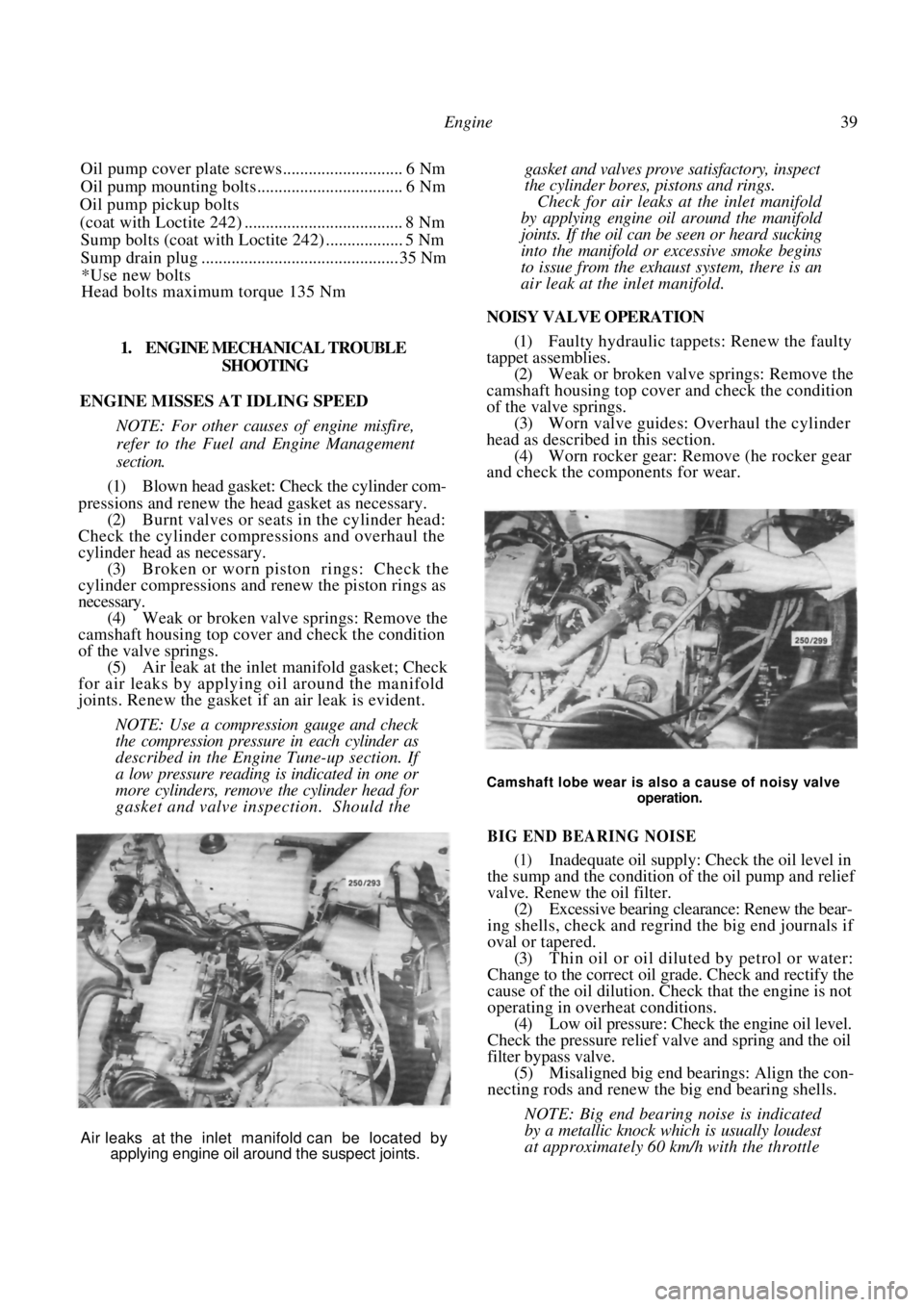
for air leaks by applying oil around the manifold
joints. Renew the gasket if an air leak is evident.
NOTE: Use a compre ssion gauge and check
the compression pressure in each cylinder as
described in the Engine Tune-up section. If
a low pressure reading is indicated in one or
more cylinders, remove the cylinder head for
gasket and valve inspection. Should the
gasket and valves prove satisfactory, inspect
the cylinder bores, pistons and rings.
Check for air leaks at the inlet manifold
by applying engine oil around the manifold
joints. If the oil can be seen or heard sucking
into the manifold or excessive smoke begins
to issue from the exhaust system, there is an
air leak at the inlet manifold.
NOISY VALVE OPERATION
(1) Faulty hydraulic tappets: Renew the faulty
tappet assemblies. (2) Weak or broken valve springs: Remove the
camshaft housing top cover and check the condition
of the valve springs. (3) Worn valve guides: Overhaul the cylinder
head as described in this section. (4) Worn rocker gear: Remove (he rocker gear
and check the components for wear.
Camshaft lobe wear is also a cause of noisy valve
operation.
BIG END BEARING NOISE
(1) Inadequate oil supply: Check the oil level in
the sump and the condition of the oil pump and relief
valve. Renew the oil filter.
(2) Excessive bearing clearance: Renew the bear-
ing shells, check and regrind the big end journals if
oval or tapered. (3) Thin oil or oil diluted by petrol or water:
Change to the correct oil grade. Check and rectify the
cause of the oil dilution. Ch eck that the engine is not
operating in overheat conditions.
(4) Low oil pressure: Check the engine oil level.
Check the pressure relief valve and spring and the oil
filter bypass valve. (5) Misaligned big end bearings: Align the con-
necting rods and renew the big end bearing shells.
NOTE: Big end bearing noise is indicated
by a metallic knock wh ich is usually loudest
at approximately 60 km/h with the throttle
Air leaks at the inlet manifold can be located by
applying engine oil around the suspect joints.
Page 41 of 238
Engine 41
DROP IN OIL PRESSURE
(1) Oil level low in the sump: Check and replen-
ish the oil to the full mark on the dipstick.
(2) Thin or diluted oil: Change to the correct oil
grade and rectify the source of dilution. (3) Oil pump relief valve stuck or spring broken;
Free up the relief valve or renew the broken relief
valve spring. (4) Excessive bearing clearance: Renew the bear-
ing shells or recondition the crankshaft journals as
necessary.
(5) Excessive wear of the oil pump components:
Renew or recondition the oil pump.
NOTE: If the vehicle is not equipped with an
oil pressure gauge re move the oil sender unit
and connect a pressure gauge into the oil
gallery. Check the oil pressure with the
engine cold and hot. If the oil pump or relief
valve are faulty. low pressure will be indi-
cated with the engine both hot and cold.
However, if the bearings are at fault a fairly
high oil pressure will be indicated when the
engine is cold, but a marked drop in pressure
will occur when the engine is hot.
ENGINE WILL NOT ROTATE
(1) Starter motor drive jammed: Remove the
starter motor. Check and renew the damaged drive
and/or flywheel ring gear.
(2) Engine overheated an d seized: Remove and
dismantle the engine. Check and renew any damaged
components. See the following note.
(3) Water in the cylinder due to a blown head
gasket or cracked cylinder block or head: Remove the
cylinder head. If the gasket is blown, check for
cylinder block and head distortion and reface if
necessary. Renew the cylinder head and/or cylinder
block if cracked.
(4) Broken crankshaft, connecting rod. piston
etc. due to overheating, fatigue etc: Remove and
dismantle the engine. Examine and renew any com-
ponents as necessary. (5) Valve head broken off due to overheating,
fatigue etc: Remove the cylinder head and check the
head, piston and cylinder bore for damage. Repair or
renew as necessary.
NOTE: Invariably when an engine seizes
because of overheating due to lack of oil
and/or water, damage is done to the bear-
ings, pistons etc. Although there may be
instances where an engine will start and run
after it has cooled down and the oil and
water have been replenished, it will usually
be found that oil consumption increases, oil
pressure decreases and the engine will be
noisier, depending on the degree of damage.
When a cylinder head gasket blows allow-
ing water into the cylinders, or compression
loss between the cylinders, it is essential to
check the gasket faces on the cylinder block
and head for distortion. Sufficient water can
enter a cylinder because of a blown head
gasket, cracked cylinder or head to prevent
an engine from rotating.
This is normally preceded by difficult
starting, misfiring, excessive steam from the
exhaust and loss of water from the radiator.
Frequent jamming of the starter motor
drive with the flywheel ring gear can be due
to a bent starter armature shaft or damaged
teeth on the drive and/or ring gear. With the
starter motor removed, the flywheel ring
gear teeth can be examined through the
starter motor mounting aperture. Renewal
of the ring gear requires removal of the
transaxle, clutch and flywheel on manual
transaxle models and the removal of the
transaxle and drive plate on automatic
transaxle models. To check for a bent arma-
ture shaft, rotate the shaft by hand while
holding the end in close proximity to a fixed
object.
2. DESCRIPTION
The 1.6 and 1.8 liter engines are basically identi-
cal in design.
Both engines share the same stroke. The 1.8 liter
engine has a larger bore thus giving it increased
capacity.
The engine is a four cylinder, inline, overhead
camshaft design transversely mounted in the front of
the vehicle.
The camshaft runs in five integral support bear-
ings in the camshaft housing which in turn is mounted
directly on to the cylinder head and retained by the
cylinder head bolts.
Camshaft end float is controlled by a retaining
plate engaged in a groove machined in the rear
camshaft journal. The camshaft is driven by the
crankshaft timing gear vi a a reinforced rubber belt.
The aluminum cross flow cylinder head houses
the tappets, rocker arms a nd valve assemblies. An oil
pressure relief valve is installed to the cylinder head to
maintain oil pressure to the hydraulic tappets at a
predetermined setting.
The exhaust valve springs are equipped with
rotators mounted below the valve springs which rotate
the exhaust valve assemblies. The rocker arms pivot
on hydraulic tappet assemblies and locate in notched
lash pads mounted on the valve stems. The camshaft
lobes bear directly onto the rocker arms and due to
the characteristics of the hydraulic tappet assemblies,
no provision is made for tappet clearance adjustment.
Page 42 of 238
42 Engine
The cylinder block is a cast iron alloy, deep skirt
design and the crankshaft is supported in the cylinder
block by five precision insert replaceable main bear-
ings. Crankshaft end float is controlled by the flanged
centre main bearing. Connecting rods are I section
forgings equipped with precision insert replaceable big
end bearings. The gudgeon pins are an interference fit
in the connecting rod and a floating fit in the piston.
The cast aluminum pistons are equipped with
two compression rings and one oil control ring.
The twin rotor, involute gear oil pump is mounted
directly to the front face of the cylinder block. The
inner rotor is internally driven by the crankshaft. The
oil pump pressure relief valve is not adjustable, and
consists of a plunger and spring mounted in the oil
pump body.
The pump draws oil through a screen in the sump
and delivers it, via a full flow replaceable oil filter, to
the oil gallery from where it is distributed to the
hydraulic tappets, camshaft and crankshaft bearings
and to the overhead rocker and valve mechanism.
3. ENGINE AND TRANSAXLE ASSEMBLY
Special Equipment Required:
To Remove and Instill — Suitable lifting tackle,
extra long chassis stands, suitable trolley
TO REMOVE
NOTE: Due to the high residual pressure
within the fuel system, it will be necessary to
depressurize the system before removing any
fuel supply components. Refer to the Fuel
and Engine Management section for the
correct procedure.
(1) Disconnect the negative battery terminal.
(2) Mark around the bonnet hinges with a soft
lead pencil Co facilitate correct installation. With the
aid of an assistant, remove the bonnet retaining bolts
and remove the bonnet from the vehicle.
(3) Drain the engine and transaxle lubricant.
(4) Open the coolant drain tap located on the
lower radiator pipe and drain the coolant. (5) Loosen the hose clips and disconnect the
heater hoses from the heater pipes at the bulkhead.
NOTE: Do not use excessive force to remove
the heater hoses from the heater pipes or the
heater core will become dislodged from the
heater unit. If necessary, cut the heater
hoses from the pipes using a sharp knife.
(6) Loosen the hose clamps and disconnect the
radiator hoses from the engine assembly. (7) Disconnect the positive lead from the bat-
tery. (8) On 1.8 liter models, disconnect the air inlet
duct.
(9) On 1.6 liter models, remove the air cleaner
assembly. Refer to the Fuel and Engine Management
section if necessary. (10) Disconnect the throttle cable from the throt-
tle body and from the camshaft housing top cover
bracket, if applicable. (11) Disconnect the fuel supply and return hoses.
Mark the hoses as an aid to installation. (12) Suitably mark and disconnect the charcoal
canister hoses. (13) Disconnect the injector wires from the injec-
tors. On 1.6 liter models, slide the wiring out from the
throttle body. (14) Disconnect the wiring fr om the throttle po-
sition sensor (TPS), idle air control (IAC) valve,
oxygen (O
2) sensor wire, coolant temperature sensor,
coolant sender and on 1.8 liter models, the manifold
air temperature (MAT) sensor. (15) Disconnect the wiring connector adjacent to
the top heater hose, the wiring from the alternator and
the two earth wires from underneath the cylinder head
bolts. (16) Lay the wiring loom over on the passenger
side of the engine compar tment, clear of the work
area.
(17) On manual transaxle models, loosen the
clutch cable adjusting nuts and remove the cable
through the slot in the lever. Remove the clutch cable
bracket from the transaxle after removing the retain-
ing bolts and place the cable to one side.
(18) Disconnect the wiring from the starter mo-
tor, speedometer sender and on manual transaxle
models, the reverse lamp switch wiring.
(19) If applicable, disconnect the power steering
lines from the pump and drain the fluid into a
container. Suitably plug the lines and the pump to
prevent the entry of dirt.
(20) On automatic transaxle models, disconnect
the selector cable and bracket from the transaxle
assembly.
Disconnect the transaxle oil cooler lines from the
transaxle. Plug the lines and fittings to prevent the
entry of dirt etc.
(21) Loosen the front wheel nuts, raise the front
of the vehicle and support it on extra long chassis
stands. Ensure that the vehicle is high enough to allow
removal of the engine from underneath. (22) Remove the front wheels and the engine
splash guards from the vehicle.
(23) On manual transaxle models, remove the
stay rod and control rod bolts and nuts and disconnect
the rods from the transaxle.
(24) Remove the lower control arm to steering
knuckle ball joint nuts and separate the ball joints
from the steering knuckle by holding a dolly or a
hammer against one side of the steering knuckle and
hitting the other side with a hammer. The taper on the
ball joint will release fr om the steering knuckle.
(25) Pull the steering knuckles outward swiftly to
Page 48 of 238
48 Engine
TO INSTAL
(1) Check that the camshaft and crankshaft
timing gears have not been moved and that the timing
marks are still aligned. It will be necessary to tempo-
rarily install the crankshaft pulley to check that the
timing marks are still aligned. (2) Install the drive belt to the crankshaft timing
gear around the water pump gear and onto the
camshaft timing gear.
NOTE: If the original drive belt is being
installed, ensure that the arrow marked on
the belt prior to removal is pointing in the
direction of rotation.
(3) Use the adjusting tool to turn the water
pump assembly sufficiently to engage the water pump
pulley with the drive belt. (4) Install the inner cover lower retaining bolt.
(5) Ensure that the drive be lt is correctly meshed
with the teeth of the camshaft, crankshaft and water
pump gears. Install the crankshaft pulley and tighten
the bolts to Specifications. (6) Adjust the drive belt as described under the
following heading.
(7) Install the drive belt outer cover and fasten
the retaining clips. (8) Install and adjust the alternator and if
equipped, the power steeri ng and air conditioning
drive belts as desc ribed in the Engine Tune-up section.
TO ADJUST
(1) Remove the alternator drive belt and if
equipped, the power steering and air conditioning
drive belts. (2) Release the clips securing the camshaft drive
belt outer cover to the inner cover and remove the
outer cover. (3) Turn the engine in the direction of rotation
until the timing marks on the camshaft and the inner
cover are aligned. (4) Loosen the water pump retaining bolts and
using the adjusting tool, rotate the water pump
housing to gain the required belt tension. The belt is
correctly tensioned when it can be grasped between
the thumb and forefinger midway between the cam-
shaft timing gear and the water pump gear and turned
ninety degrees from i t s operating position.
After the belt has been tensioned, tighten the
water pump retaining bolts to the specified torque.
NOTE: Over tensioning of the drive belt will
result in noisy operation and premature
wear of the belt.
(6) Install the outer drive belt cover.
(7) Install and adjust the alternator, and if
equipped, the power steering and air conditioning
drive belts as desc ribed in the Engine Tune-up section. 6. CAMSHAFT. ROCKER ARMS AND TAPPETS
Special Equipment Required:
To Check Camshaft — Dial gauge, Vee blocks and
micrometers
To Install — Drive belt adjusting tool
It is recommended that a new cylinder head
gasket is installed and the cylinder head bolts renewed
when the camshaft housing is removed.
TO REMOVE
(1) Disconnect the negative battery terminal.
Remove the nuts securing the earth wires to the
cylinder head bolts and remove the earth wires.
(2) On 1.6 liter models, remove the air cleaner
wingnuts and withdraw the air cleaner.
(3) Disconnect the engine breather hoses from
the camshaft housing and the camshaft housing top
cover. (4) Remove the camshaft housing top cover
retaining bolts and remove the top cover. Discard the
gasket.
(5) Remove the camshaft dr ive belt as described
under the previous heading. (6) Using an open ended spanner, hold the
camshaft between the inle t and exhaust lobes of
number four cylinder and remove the camshaft timing
gear retaining bolt and the camshaft timing gear.
(7) Remove the distributor, distributor cap and
high tension leads. If necessary refer to the Fuel and
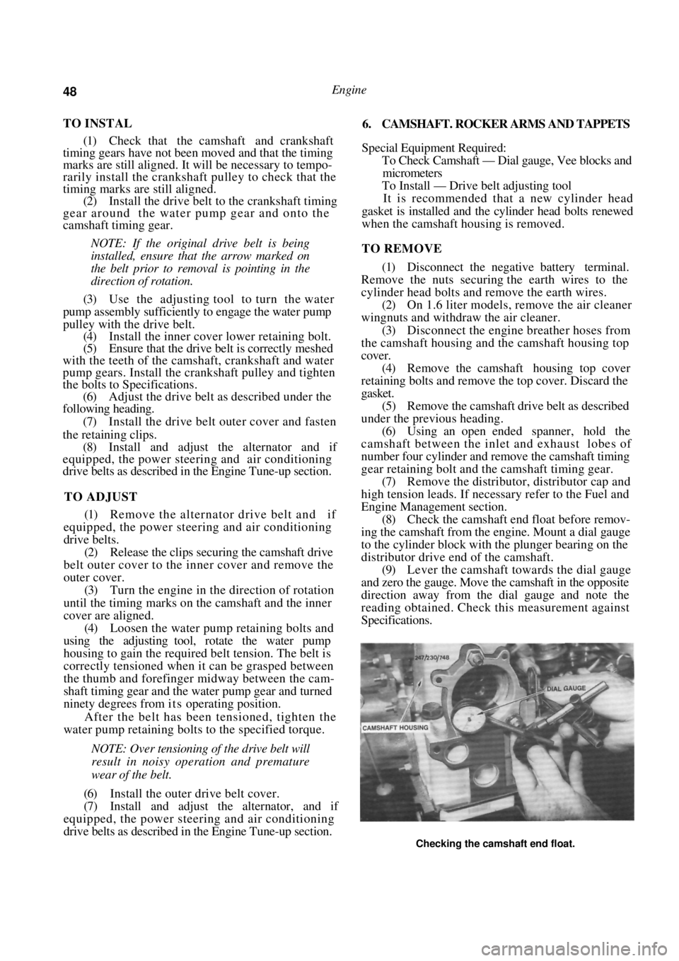
Engine Management section. (8) Check the camshaft end float before remov-
ing the camshaft from the engine. Mount a dial gauge
to the cylinder block with the plunger bearing on the
distributor drive end of the camshaft. (9) Lever the camshaft towards the dial gauge
and zero the gauge. Move the camshaft in the opposite
direction away from the dial gauge and note the
reading obtained. Check this measurement against
Specifications.
Checking the camshaft end float.
Page 49 of 238
Engine 49
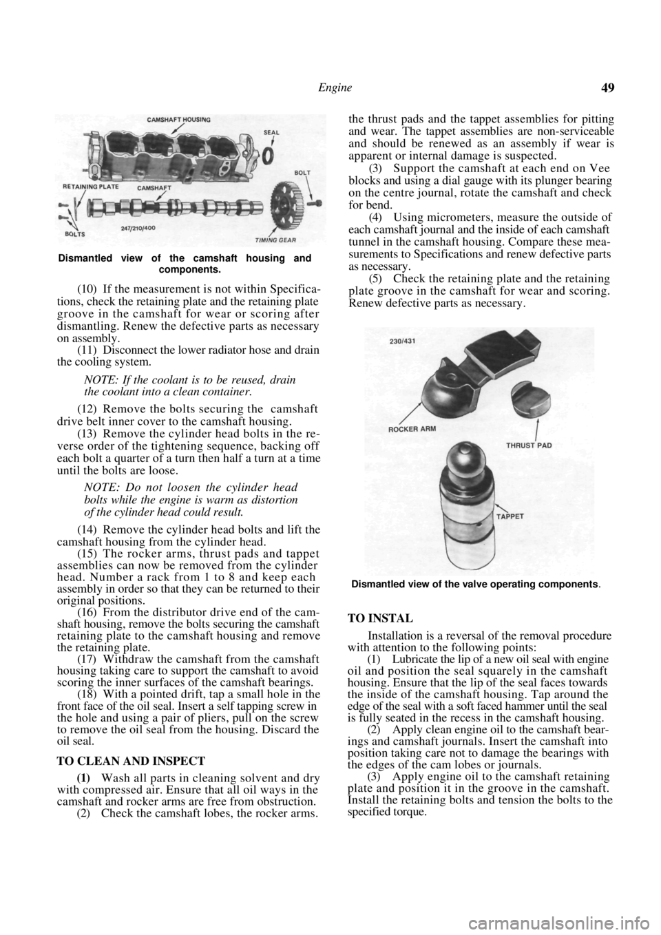
Dismantled view of the camshaft housing and components.
(10) If the measurement is not within Specifica-
tions, check the retaining plate and the retaining plate
groove in the camshaft for wear or scoring after
dismantling. Renew the defective parts as necessary
on assembly. (11) Disconnect the lower radiator hose and drain
the cooling system.
NOTE: If the coolant is to be reused, drain
the coolant into a clean container.
(12) Remove the bolts securing the camshaft
drive belt inner cover to the camshaft housing. (13) Remove the cylinder head bolts in the re-
verse order of the tighten ing sequence, backing off
each bolt a quarter of a turn then half a turn at a time
until the bolts are loose.
NOTE: Do not loosen the cylinder head
bolts while the engine is warm as distortion
of the cylinder head could result.
(14) Remove the cylinder head bolts and lift the
camshaft housing from the cylinder head. (15) The rocker arms, thrust pads and tappet
assemblies can now be removed from the cylinder
head. Number a rack from 1 to 8 and keep each
assembly in order so that they can be returned to their
original positions.
(16) From the distributor drive end of the cam-
shaft housing, remove the bolts securing the camshaft
retaining plate to the camshaft housing and remove
the retaining plate. (17) Withdraw the camshaft from the camshaft
housing taking care to supp ort the camshaft to avoid
scoring the inner surfaces of the camshaft bearings.
(18) With a pointed drift, tap a small hole in the
front face of the oil seal. Insert a self tapping screw in
the hole and using a pair of pliers, pull on the screw
to remove the oil seal from the housing. Discard the
oil seal.
TO CLEAN AND INSPECT
(1) Wash all parts in cleaning solvent and dry
with compressed air. Ensure that all oil ways in the
camshaft and rocker arms are free from obstruction.
(2) Check the camshaft lobes, the rocker arms. the thrust pads and the ta
ppet assemblies for pitting
and wear. The tappet assemblies are non-serviceable
and should be renewed as an assembly if wear is
apparent or internal damage is suspected.
(3) Support the camshaft at each end on Vee
blocks and using a dial gauge with its plunger bearing
on the centre journal, rotate the camshaft and check
for bend. (4) Using micrometers, measure the outside of
each camshaft journal and the inside of each camshaft
tunnel in the camshaft housing. Compare these mea-
surements to Specifications and renew defective parts
as necessary. (5) Check the retaining plate and the retaining
plate groove in the camshaft for wear and scoring.
Renew defective parts as necessary.
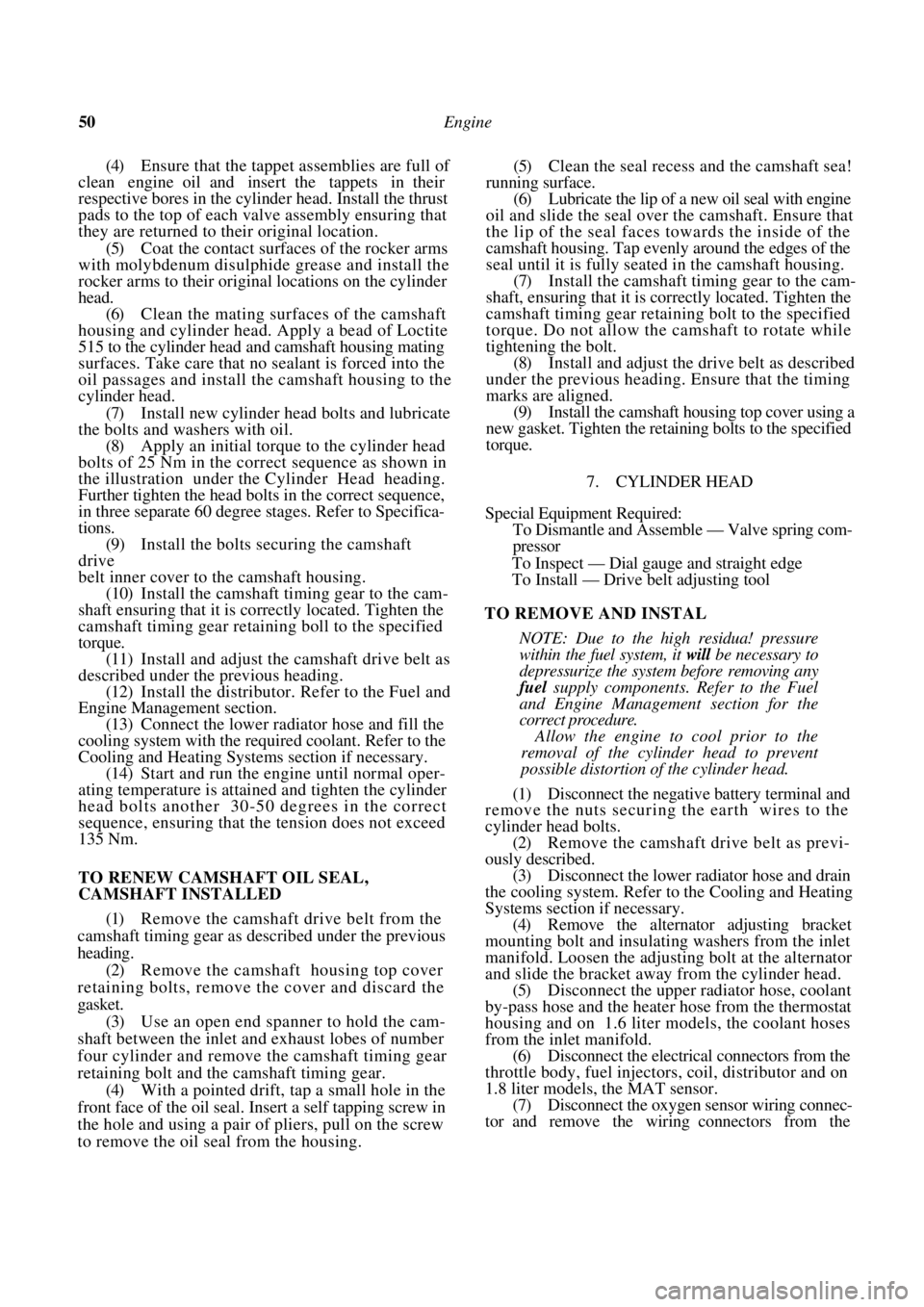
Dismantled view of the valve operating components.
TO INSTAL
Installation is a reversal of the removal procedure
with attention to the following points:
(1) Lubricate the lip of a new oil seal with engine
oil and position the seal squarely in the camshaft
housing. Ensure that the li p of the seal faces towards
the inside of the camshaft housing. Tap around the
edge of the seal with a soft faced hammer until the seal
is fully seated in the recess in the camshaft housing. (2) Apply clean engine oil to the camshaft bear-
ings and camshaft journals. Insert the camshaft into
position taking care not to damage the bearings with
the edges of the cam lobes or journals. (3) Apply engine oil to the camshaft retaining
plate and position it in the groove in the camshaft.
Install the retaining bolts and tension the bolts to the
specified torque.
Page 50 of 238
50 Engine
(4) Ensure that the tappet assemblies are full of
clean engine oil and insert the tappets in their
respective bores in the cylinde r head. Install the thrust
pads to the top of each valve assembly ensuring that
they are returned to their original location.
(5) Coat the contact surfaces of the rocker arms
with molybdenum disulphide grease and install the
rocker arms to their origin al locations on the cylinder
head. (6) Clean the mating surfaces of the camshaft
housing and cylinder head. Apply a bead of Loctite
515 to the cylinder head and camshaft housing mating
surfaces. Take care that no sea lant is forced into the
oil passages and install the camshaft housing to the
cylinder head.
(7) Install new cylinder head bolts and lubricate
the bolts and washers with oil.
(8) Apply an initial torque to the cylinder head
bolts of 25 Nm in the corr ect sequence as shown in
the illustration under the Cylinder Head heading.
Further tighten the head bolts in the correct sequence,
in three separate 60 degree stages. Refer to Specifica-
tions. (9) Install the bolts securing the camshaft
drive
belt inner cover to the camshaft housing. (10) Install the camshaft timing gear to the cam-
shaft ensuring that it is correctly located. Tighten the
camshaft timing gear retain ing boll to the specified
torque. (11) Install and adjust the camshaft drive belt as
described under the previous heading. (12) Install the distributor. Refer to the Fuel and
Engine Management section.
(13) Connect the lower radiat or hose and fill the
cooling system with the required coolant. Refer to the
Cooling and Heating Systems section if necessary. (14) Start and run the engine until normal oper-
ating temperature is attained and tighten the cylinder
head bolts another 30-50 degrees in the correct
sequence, ensuring that the tension does not exceed
135 Nm.
TO RENEW CAMSHAFT OIL SEAL,
CAMSHAFT INSTALLED
(1) Remove the camshaft drive belt from the
camshaft timing gear as described under the previous
heading.
(2) Remove the camshaft housing top cover
retaining bolts, remove the cover and discard the
gasket.
(3) Use an open end spanner to hold the cam-
shaft between the inlet and exhaust lobes of number
four cylinder and remove the camshaft timing gear
retaining bolt and the camshaft timing gear. (4) With a pointed drift, tap a small hole in the
front face of the oil seal. Insert a self tapping screw in
the hole and using a pair of pliers, pull on the screw
to remove the oil seal from the housing.
(5) Clean the seal recess and the camshaft sea!
running surface. (6) Lubricate the lip of a new oil seal with engine
oil and slide the seal over the camshaft. Ensure that
the lip of the seal faces to wards the inside of the
camshaft housing. Tap evenly around the edges of the
seal until it is fully seated in the camshaft housing.
(7) Install the camshaft timing gear to the cam-
shaft, ensuring that it is co rrectly located. Tighten the
camshaft timing gear retain ing bolt to the specified
torque. Do not allow the camshaft to rotate while
tightening the bolt. (8) Install and adjust the drive belt as described
under the previous heading. Ensure that the timing
marks are aligned. (9) Install the camshaft hou sing top cover using a
new gasket. Tighten the retaining bolts to the specified
torque.
7. CYLINDER HEAD
Special Equipment Required:
To Dismantle and Assemble — Valve spring com-
pressor
To Inspect — Dial gauge and straight edge
To Install — Drive belt adjusting tool
TO REMOVE AND INSTAL
NOTE: Due to the high residua! pressure
within the fuel system, it will be necessary to
depressurize the system before removing any
fuel supply components. Refer to the Fuel
and Engine Management section for the
correct procedure.
Allow the engine to cool prior to the
removal of the cylinder head to prevent
possible distortion of the cylinder head.
(1) Disconnect the negative battery terminal and
remove the nuts securing the earth wires to the
cylinder head bolts.
(2) Remove the camshaft drive belt as previ-
ously described.
(3) Disconnect the lower radiator hose and drain
the cooling system. Refer to the Cooling and Heating
Systems section if necessary. (4) Remove the alternator adjusting bracket
mounting bolt and insulating washers from the inlet
manifold. Loosen the adjusting bolt at the alternator
and slide the bracket away from the cylinder head. (5) Disconnect the upper radiator hose, coolant
by-pass hose and the heater hose from the thermostat
housing and on 1.6 liter m odels, the coolant hoses
from the inlet manifold. (6) Disconnect the electrica l connectors from the
throttle body, fuel injectors, coil, distributor and on
1.8 liter models, the MAT sensor. (7) Disconnect the oxygen sensor wiring connec-
tor and remove the wiring connectors from the
Page 52 of 238

52 Engine
leaks and rectify as necessary. Check and if necessary
adjust the ignition timing as described in the Engine
Tune-up section.
(16) When the engine has reached normal oper-
ating temperature, tighten the cylinder head bolts
another 40-50 degrees in the correct sequence shown
in the illustration, ensuring that the tension does not
exceed 135 Nm.
TO DISMANTLE
(1) Remove the cylinder head as previously
described.
(2) Remove the thermostat housing and sealing
ring from the cylinder head.
(3) Remove the nuts securing the inlet and
exhaust manifolds to the cylinder head and remove
the manifolds. Discard the gaskets. (4) Lift the rocker arm and thrust pad from the
top of each valve assembly, keeping them in order for
assembly to their or iginal locations.
(5) Slide each hydraulic tappet from its bore in
the cylinder head, also keeping them in order for
assembly to their or iginal locations.
(6) Before removing the valves the deposits in
Installed view of the cylinder head oil pressure relief
valve.
the combustion chambers s hould be removed. Care
should be taken not to damage the cylinder head
gasket face.
(7) Using a valve spring compressor, compress
each spring in turn. Remove the split retaining collets
and slowly release the compressor.
(8) Remove the valve spring retainers and valve
springs. (9) Remove the valve stem seals from the top of
the valve guides and detach the exhaust valve rotators
and the inlet valve spring seats, from the cylinder
head. (10) Remove any burrs from the valve stem
grooves to prevent damage to the valve guides when
the valves are removed from the cylinder head. (11) Remove the valves, keeping them in order
for assembly to their original locations.
NOTE: To keep the valve assemblies in
order have a rack numbered from 1 to 8 and
instill the components in this rack, starting
from the front of the cylinder head.
(12) If the oil pressure relief valve in the cylinder
head is to be renewed, proceed as follows:
(a) Using a drift, remove the welch plug from
the distributor end of the cylinder head. (b) Remove the recessed screw from the thermo-
stat housing end of the cylinder head. (c) Using a long brass drift inserted in the oilway
through the tappet bores from the thermostat housing
end. remove the oil pressure relief valve from the
cylinder head. Discard the relief valve.
TO CLEAN AND INSPECT
(1) Clean the valves thoroughly and discard any
burnt, warped or cracked valves. (2) Have the valves refaced to the recommended
angle on a valve refacing machine. The valve stem tips
are specially hardened and should not be refaced.
Dismantled view of the valve and spring components.
Page 54 of 238

54 Engine
in the valve stem groove before releasing the spring
compressor. A sharp tap to the top of the valve stem
with a soft faced hammer will ensure that the collets
are correctly seated.
(7) Install the inlet and exhaust manifolds using
new gaskets and tighten the mounting nuts to the
specified torque as previously described. (8) Install a new sealing ring to the
thermostat
housing, install the housing to the cylinder head and
tighten the mounting bolts to the specified torque.
(9) Ensure that the lappet assemblies are filled
with clean engine oil and install the tappets in
their
respective bores in the cylinder head. (10) Install the thrust pads to the top of each
valve
assembly, ensuring that they are returned to their
original locations. (11) Coat the contact surfaces of the rocker arms
with molybdenum disulphide grease and install the
rocker arms to their origin al locations on the cylinder
head. (12) Install the cylinder head to the engine as
previously described.
8. ENGINE SUMP AND OIL PUMP PICKUP . PIPE
TO REMOVE
(1) Disconnect the negative battery terminal.
(2) Raise the front of the vehicle and support it
on chassis stands. Refer to the Wheels and Tires
section for the correct procedure.
(3) Remove the sump plug and drain the engine
oil into a container. Install and tighten the plug
after the oil has been drained.
(4)
Remove the engine pipe as described at the
end of this section.
(5) Remove the nuts and bolts retaining the
engine crossmember to the vehicle underbody and
withdraw the crossmember from the vehicle. On
automatic transaxle models, it will be necessary to
release the selector cable from the crossmember
bracket.
(6) Remove the sump retaining bolts and wash-
ers and if necessary firmly bump the sump with the
palm of the hand and remove it from the engine. (7) Remove the bolts retaining the oil pump
pickup pipe to the oil pump and disconnect the
pickup pipe from the support bracket. Remove the
pickup pipe and discard the O ring seal. (8) Remove the scraper and gasket from the
engine. (9) Clean the gasket material from the sump,
engine block and the scraper.
NOTE: If the scraper assembly is damaged
it should be renewed.
TO INSTAL
(1) Wash the inside of the sump to remove
carbon and sludge deposits. Check for any metal
deposits which may indicate an imminent component
failure. (2) Inspect the sump for dents and cracks.
Ensure that the gasket sea ling face is not distorted or
damaged. (3) Clean the pickup pipe screen with solvent
and a brush. (4) Using a new O ring seal, install the pickup
pipe. Coat the pipe retain ing bolts with Loctite 242
and tighten to the specified torque. (5) Apply a bead of KP510-00150 sealer or
equivalent to the oil pump to cylinder block mating
joint area. (6) Ensure that the sump gasket is correctly
located on the scraper and install the sump to
the
engine. Apply Loctite 242 to the threads of the sump
bolts and tighten the bolts to the specified torque.
(7) Install the front exhaust pipe using a
new
gasket and coat the threads of the flange nuts with an
anti-seize compound before tightening the nuts to the
specified torque. (8) Install the engine crossmember and
tighten
the nuts and bolts securely. If applicable, connect the
automatic transaxle selector cable to the crossmember
bracket. (9) Ensure that the sump drain plug is secure
and lower the vehicle to the ground. (10) Fill the engine with the specified amount and
grade of engine oil. Refer to the Lubrication and
Maintenance section if necessary. (11) Start and run the engine and check for oil
leaks.
View of the sump, oil pump pickup, gasket and scraper
removed from the engine.