tow NISSAN PULSAR 1987 Workshop Manual
[x] Cancel search | Manufacturer: NISSAN, Model Year: 1987, Model line: PULSAR, Model: NISSAN PULSAR 1987Pages: 238, PDF Size: 28.91 MB
Page 7 of 238
VEHICLE IDENTIFICATION AND GENERAL SPECIFICATIONS
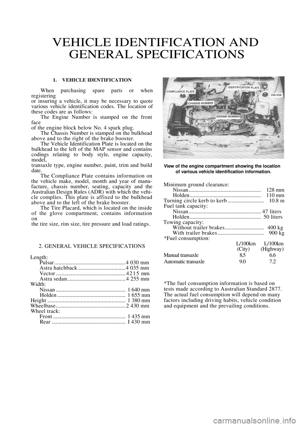
1. VEHICLE IDENTIFICATION
When purchasing spare parts or when
registering
or insuring a vehicle, it may be necessary to quote
various vehicle identification codes. The location of
these codes are as follows: The Engine Number is stamped on the front
face
of the engine block below No. 4 spark plug. The Chassis Number is stamped on the bulkhead
above and to the right of the brake booster. The Vehicle Identification Plate is located on the
bulkhead to the left of the MAP sensor and contains
codings relating to body style, engine capacity,
model,
transaxle type, engine number, paint, trim and build
date. The Compliance Plate contains information on
the vehicle make, model, month and year of manu-
facture, chassis number, seating, capacity and the
Australian Design Rules (ADR) with which the vehi-
cle complies. This plate is affixed to the bulkhead
above and to the left of the brake booster. The Tire Placard, which is located on the inside
of the glove compartment, contains information
on
the tire size, rim size, tire pressure and load ratings.
2. GENERAL VEHICLE SPECIFICATIONS
Length:
Pulsar ................................................... 4 030 mm
Astra hatchback .................................. 4 035 mm
Vector ..................................................4215 mm
Astra sedan.......................................... 4 255 mm
Width:
Nissan.................................................. 1 640 mm
Holden ................................................. 1 655 mm
Height ........................................................ 1 380 mm
Wheelbase .................................................. 2 430 mm
Wheel track:
Front .................................................... 1 435 mm
Rear ..................................................... I 430 mm
View of the engine compartment showing the location
of various vehicle identification information.
Minimum ground clearance:
Nissan.................................................... 128 mm
Holden ................................................... 110 mm
Turning circle kerb to kerb .......................... 10.8 m
Fuel tank capacity:
Nissan.................................................... 47 liters
Holden ................................................... 50 liters
Towing capacity:
Without trailer brakes............................ 400 kg
With trailer brakes ................................. 900 kg
*Fuel consumption:
L/100km L/100km
(City) (Highway)
Manual transaxle 8.5 6.6
Automatic transaxle 9.0 7.2
*The fuel consumption information is based on
tests made according to Australian Standard 2877.
The actual fuel consumption will depend on many
factors including driving habits, vehicle condition
and equipment and the prevailing conditions.
Page 11 of 238
General Information 11
Lifting Equipment
When using lifting equipment to lift heavy com-
ponents such as the engine and/or transmission, use
metal slings or chain in preference to rope. If rope
must be used, ensure that it is not placed against sharp
edges on the component.
Automotive Lubricants and Solvents
Avoid prolonged skin contact with oils, greases
and solvents as some can cause skin irritations and
dermatitis.
Exercise caution when us ing cleaning solvents as
many are inflammable. Do not smoke. Keep naked
flames and sparks clear of the work area.
Compressed Air
Never point an air hose at another person or allow
compressed air to blow onto your skin. High pressure
air forced against the skin can enter the bloodstream
and prove fatal.
Suspension and Steering Components
Damaged suspension and steering components
should not be welded. Many of these components are
fabricated from toughened metals. If welded they may
lose their strength or become brittle. Damaged com-
ponents should be renewed.
Air Conditioning
Avoid disconnecting air conditioning hoses as
escaping refrigerant can cause frostbite. The refriger-
ant is highly flammable and when burnt, a poisonous
gas is produced.
VEHICLE SAFETY
To prevent damage to the vehicle during servicing
or repair work, note the following precautions.
Brake Fluid
If spilt on the vehicle paintwork, brake fluid
should be immediately washed away with clean water
and allowed to dry naturally, not wiped with a cloth.
Catalytic Converter
The following should be observed to prevent
damage to the catalytic converter:
Do not operate the vehicle on leaded fuel.
Do not push or tow start the vehicle.
Do not allow the engine to idle for prolonged
periods.
Do not switch the ignition off while the vehicle is
in motion and the transmission is in gear.
Do not 'prime' the engine by pouring fuel into the
inlet manifold.
Do not operate the vehicle if the engine is
misfiring.
Avoid running the vehicle out of fuel.
Ensure that the engine oil is formulated to contain
low phosphorus levels.
Electronic Components
The electronic components of the ignition and
fuel injection systems can be damaged by the use of
incorrect testing equipment.
It is essential in all tests where voltage or resis-
tance is to be measured that a digital display multi-
meter with a minimum 10 megohm input impedance
be used.
Some types of tachometers, timing lights and
ignition system analyzers are not compatible with
certain engine electronic systems. It is therefore
recommended that the manufacturer of the test equip-
ment be consulted before using the equipment.
Jump starting, or being jump started by another
vehicle can cause damage to the electronic compon-
ents of the vehicle. Refer to the Roadside Trouble
shooting section for the correct jump starting proce-
dure.
3. GENERAL REPAIR PROCEDURES
SEIZED FASTENERS
Seized bolts, nuts or screws should first have a
liberal amount of penetrating oil applied. The fastener
should be left for a period of time to allow the oil to
penetrate and soften the corrosion which is causing
the binding.
Often, a sharp hammer blow to the head of the
fastener can dislodge the corrosion and permit it to be
loosened.
An impact driver, which can be fitted with a
socket or screwdriver bit, can be used to loosen a
seized fastener.
Another method is to heat the component in
which the fastener is seized. However, extreme cau-
tion should be exercised when heating aluminum
alloy components as the melting point is much lower
than that of steel.
If the above methods fail to free a seized nut,
carefully hacksaw through one side of the nut until it
can be split. Care should be taken that the threads of
the bolt or stud are not damaged.
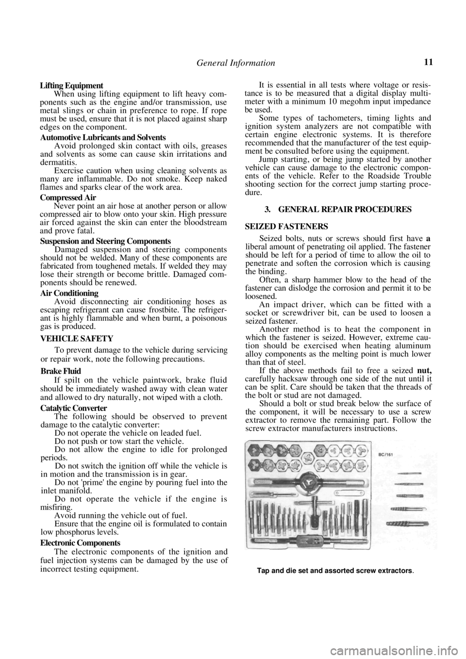
Should a bolt or stud break below the surface of
the component, it will be necessary to use a screw
extractor to remove the remaining part. Follow the
screw extractor manuf acturers instructions.
Tap and die set and assorted screw extractors.
Page 12 of 238
12 General Information
Damaged threads can be repaired using a die nut
on studs and bolts, and a tap on nuts and threaded
holes in castings. If the threads of a threaded hole are
damaged beyond repair, it will be necessary to drill
and tap the hole to a larger size. Alternatively, a
Helicoil insert can be used to Testore the hole to the
original thread size.
STUDS
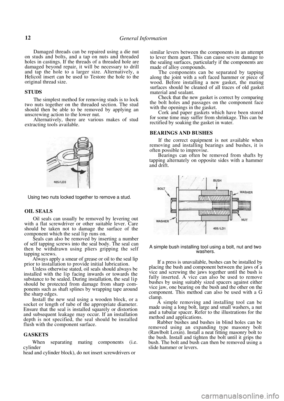
The simplest method for removing studs is to lock
two nuts together on the threaded section. The stud
should then be able to be removed by applying an
unscrewing action to the lower nut.
Alternatively, there are various makes of stud
extracting tools available.
Using two nuts locked together to remove a stud.
OIL SEALS
Oil seals can usually be removed by levering out
with a flat screwdriver or other suitable lever. Care
should be taken not to damage the surface of the
component which the seal lip runs on.
Seals can also be removed by inserting a number
of self tapping screws into the seal body. The seal can
then be withdrawn using pliers gripping the self
tapping screws.
Always apply a smear of grease or oil to the seal lip
prior to installation to provide initial lubrication.
Unless otherwise stated, oil seals should always be
installed with the lip facing inwards or towards the
substance to be sealed. Duri ng installation, the seal l i p
should be protected from damage from sharp com-
ponents such as shaft splines by wrapping tape around
the sharp edges.
Install the new seal using a wooden block, or a
socket or length of tube of the appropriate diameter.
Ensure that the seal is installed squarely or distortion
and subsequent leakage may occur. If an installation
depth is not specified, th e seal should be installed
flush with the component surface.
GASKETS
When separating mating components (i.e.
cylinder
head and cylinder block), do not insert screwdrivers or
similar levers between the components in an attempt
to lever them apart. This can cause severe damage to
the sealing surfaces, particularly if the components are
made of alloy compounds.
The components can be separated by tapping
along the joint with a soft faced hammer or piece of
wood. Before installing a new gasket, the mating
surfaces should be cleaned of all traces of old gasket
material and sealant.
Check that the new gasket is correct by comparing
the bolt holes and passages on the component face
with the openings in the gasket.
Cork and paper gaskets which have been stored
for some time may suffer from shrinkage. This can be
rectified by soaking the gasket in water.
BEARINGS AND BUSHES
If the correct equipment is not available when
removing and installing bearings and bushes, it is
often possible to improvise.
Bearings can often be removed from shafts by
tapping alternately on opposite sides with a hammer
and drift.
A simple bush installing tool using a bolt, nut and two
washers.
If a press is unavailable, bushes can be installed by
placing the bush and component between the jaws of a
vice and screwing the jaws together until the bush is
fully inserted. A vice can also be used to remove
bushes by using suitably sized spacers against either
vice jaw, one bearing on the bush and the other on the
component. This method can also be used with a G
clamp.
A simple removing and installing tool can be
made using a long bolt, large and small washers, a nut
and a tubular spacer. Refer to the illustrations for the
method and applications.
Rubber bushes and bushes in blind holes can be
removed using an expanding type masonry bolt
(Rawlbolt Loxin). Install a neat fitting masonry bolt to
the bush. Install and tighten the bolt until it grips the
bush. The bolt and bush can then be removed using a
slide hammer or levers.
Page 28 of 238
Engine Tune-up
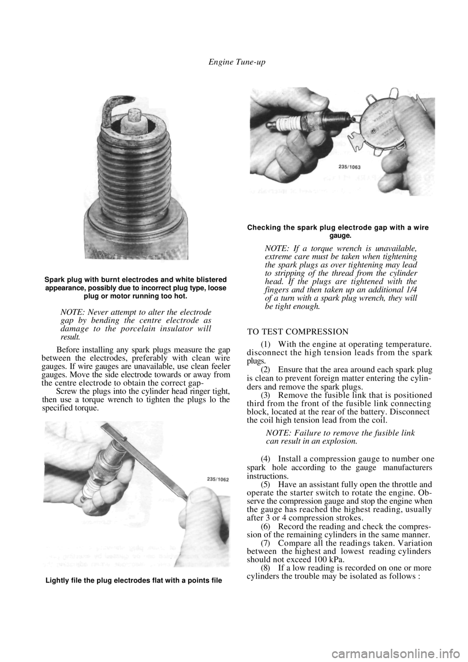
Spark plug with burnt electrodes and white blistered
appearance, possibly due to incorrect plug type, loose
plug or motor running too hot.
NOTE: Never attempt to alter the electrode
gap by bending the centre electrode as
damage to the porcelain insulator will
result.
Before installing any spark plugs measure the gap
between the electrodes, pref erably with clean wire
gauges. If wire gauges are una vailable, use clean feeler
gauges. Move the side electrode towards or away from
the centre electrode to obtain the correct gap-
Screw the plugs into the cylinder head ringer tight,
then use a torque wrench to tighten the plugs lo the
specified torque.
Checking the spark plug electrode gap with a wire
gauge.
NOTE: If a torque wrench is unavailable,
extreme care must be taken when tightening
the spark plugs as over tightening may lead
to stripping of the thread from the cylinder
head. If the plugs are tightened with the
fingers and then taken up an additional 1/4
of a turn with a spark plug wrench, they will
be tight enough.
TO TEST COMPRESSION
(1) With the engine at operating temperature.
disconnect the high tension leads from the spark
plugs.
(2) Ensure that the area around each spark plug
is clean to prevent foreign matter entering the cylin-
ders and remove the spark plugs. (3) Remove the fusible link that is positioned
third from the front of th e fusible link connecting
block, located at the rear of the battery. Disconnect
the coil high tension lead from the coil.
NOTE: Failure to remove the fusible link
can result in an explosion.
(4) Install a compression gauge to number one
spark hole according to the gauge manufacturers
instructions. (5) Have an assistant fully open the throttle and
operate the starter switch to rotate the engine. Ob-
serve the compression gauge and stop the engine when
the gauge has reached the highest reading, usually
after 3 or 4 compression strokes.
(6) Record the reading a nd check the compres-
sion of the remaining cylinders in the same manner.
(7) Compare all the readings taken. Variation
between the highest and lowest reading cylinders
should not exceed 100 kPa. (8) If a low reading is recorded on one or more
cylinders the trouble may be isolated as follows :
Lightly file the plug electrodes flat with a points file
Page 38 of 238
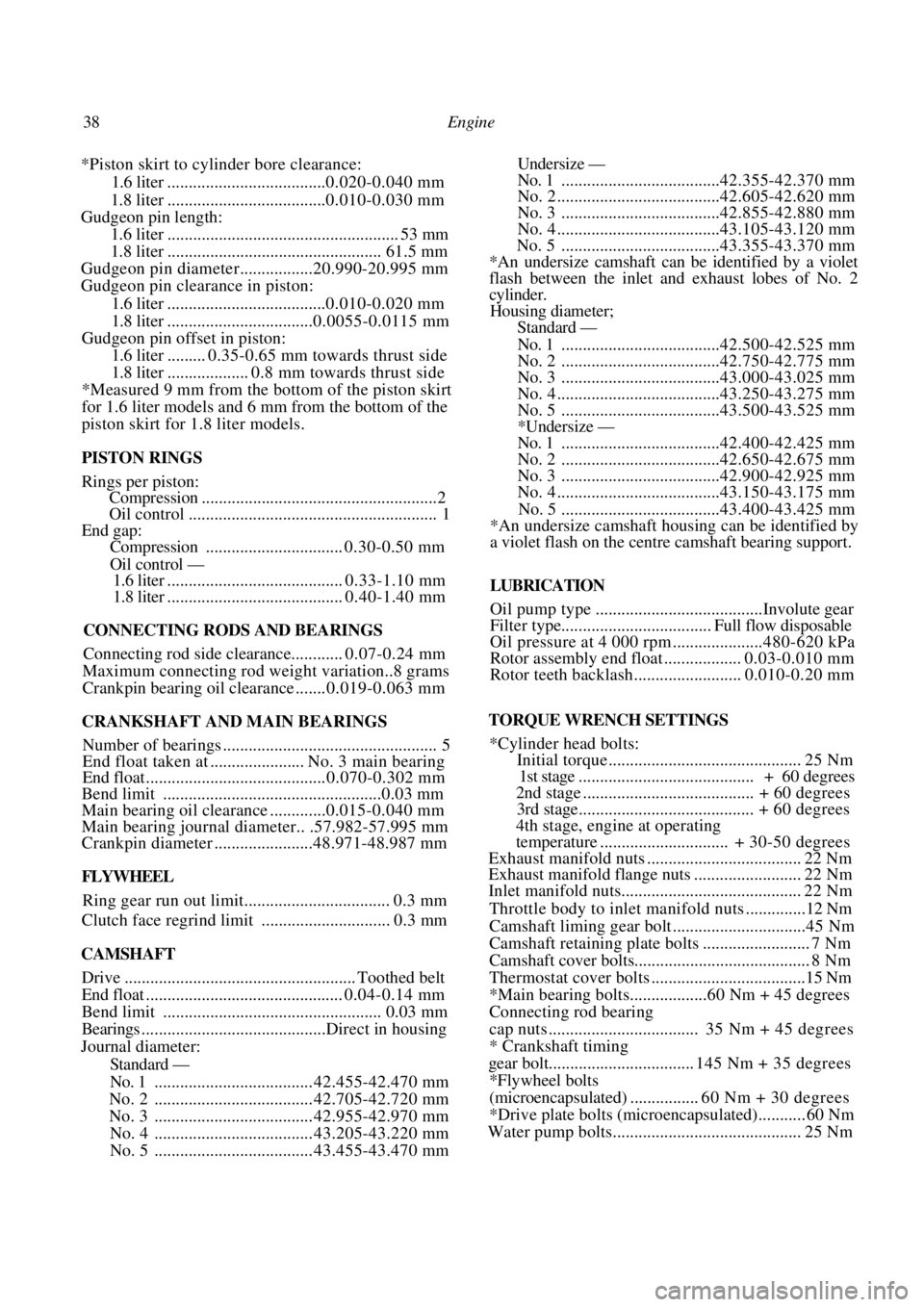
38 Engine
*Piston skirt to cylinder bore clearance:
1.6 liter .....................................0. 020-0.040 mm
1.8 liter .....................................0. 010-0.030 mm
Gudgeon pin length:
1.6 liter ...................................................... 53 mm
1.8 liter .................................................. 61.5 mm
Gudgeon pin diameter.................20.990-20.995 mm
Gudgeon pin clearance in piston:
1.6 liter .....................................0. 010-0.020 mm
1.8 liter ..................................0. 0055-0.0115 mm
Gudgeon pin offset in piston:
1.6 liter......... 0.35-0.65 mm towards thrust side
1.8 liter................... 0.8 mm towards thrust side
*Measured 9 mm from the bottom of the piston skirt
for 1.6 liter models and 6 mm from the bottom of the
piston skirt for 1.8 liter models.
PISTON RINGS
Rings per piston:
Compression .......................................................2
Oil contro l .......................................................... 1
End gap:
Compression ................................ 0.30-0.50 mm
Oil control —
1.6 liter ......................................... 0.33-1.10 mm
1.8 liter ......................................... 0.40-1.40 mm
CONNECTING RODS AND BEARINGS
Connecting rod side clearance............ 0.07-0.24 mm
Maximum connecting rod weight variation..8 grams
Crankpin bearing oil clearance ....... 0. 019-0.063 mm
CRANKSHAFT AND MAIN BEARINGS
Number of bearings .................................................. 5
End float taken at ...................... No. 3 main bearing
End float .......................................... 0.070-0.302 mm
Bend limit ...................................................0.03 mm
Main bearing oil clearance .............0. 015-0.040 mm
Main bearing journal diameter.. .57.982-57.995 mm
Crankpin diameter .......................48.971-48.987 mm
FLYWHEEL
Ring gear run out limit.................................. 0.3 mm
Clutch face regrind limit .............................. 0.3 mm
CAMSHAFT
Drive ...................................................... Toothed belt
End float .............................................. 0.04-0.14 mm
Bend limit ................................................... 0.03 mm
Bearings ...........................................Direct in housing
Journal diameter:
Standard —
No. 1 ..................................... 42. 455-42.470 mm
No. 2 ..................................... 42. 705-42.720 mm
No. 3 ..................................... 42.955-42.970 mm
No. 4 ..................................... 43.205-43.220 mm
No. 5 ..................................... 43.455-43.470 mm
Undersize —
No. 1 .....................................42.355-42.370 mm
No. 2 ......................................42.605-42.620 mm
No. 3 .....................................42.855-42.880 mm
No. 4 ......................................43.105-43.120 mm
No. 5 .....................................43. 355-43.370 mm
*An undersize camshaft can be identified by a violet
flash between the inlet and exhaust lobes of No. 2
cylinder.
Housing diameter;
Standard —
No. 1 .....................................42. 500-42.525 mm
No. 2 .....................................42.750-42.775 mm
No. 3 .....................................43.000-43.025 mm
No. 4 ......................................43.250-43.275 mm
No. 5 .....................................43.500-43.525 mm
*Undersize —
No. 1 .....................................42.400-42.425 mm
No. 2 .....................................42.650-42.675 mm
No. 3 .....................................42.900-42.925 mm
No. 4 ......................................43.150-43.175 mm
No. 5 .....................................43.400-43.425 mm
*An undersize camshaft housing can be identified by
a violet flash on the centre camshaft bearing support.
LUBRICATION
Oil pump type .......................................Involute gear
Filter type................................... Full flow disposable
Oil pressure at 4 000 rpm .....................480-620 kPa
Rotor assembly end float .................. 0.03-0. 010 mm
Rotor teeth backlash ......................... 0.010-0.20 mm
TORQUE WRENCH SETTINGS
*Cylinder head bolts:
Initial torque ............................................. 25 Nm
1st stage ......................................... + 60 degrees
2nd stage ........................................ + 60 degrees
3rd stage......................................... + 60 degrees
4th stage, engine at operating
temperature .............................. + 30-50 degrees
Exhaust manifold nuts .................................... 22 Nm
Exhaust manifold flange nuts ......................... 22 Nm
Inlet manifold nuts.......................................... 22 Nm
Throttle body to inlet manifold nuts ..............12 Nm
Camshaft liming gear bolt ...............................45 Nm
Camshaft retainin g plate bolts ......................... 7 Nm
Camshaft cover bolts......................................... 8 Nm
Thermostat cover bolts ....................................15 Nm
*Main bearing bolts..................60 Nm + 45 degrees
Connecting rod bearing
cap nuts ................................... 35 Nm + 45 degrees
* Crankshaft timing
gear bolt.................................. 145 Nm + 35 degrees
*Flywheel bolts
(microencapsulated) ................ 60 Nm + 30 degrees
*Drive plate bolts (microencapsulated)........... 60 Nm
Water pump bolts............................................ 25 Nm
Page 48 of 238
48 Engine
TO INSTAL
(1) Check that the camshaft and crankshaft
timing gears have not been moved and that the timing
marks are still aligned. It will be necessary to tempo-
rarily install the crankshaft pulley to check that the
timing marks are still aligned. (2) Install the drive belt to the crankshaft timing
gear around the water pump gear and onto the
camshaft timing gear.
NOTE: If the original drive belt is being
installed, ensure that the arrow marked on
the belt prior to removal is pointing in the
direction of rotation.
(3) Use the adjusting tool to turn the water
pump assembly sufficiently to engage the water pump
pulley with the drive belt. (4) Install the inner cover lower retaining bolt.
(5) Ensure that the drive be lt is correctly meshed
with the teeth of the camshaft, crankshaft and water
pump gears. Install the crankshaft pulley and tighten
the bolts to Specifications. (6) Adjust the drive belt as described under the
following heading.
(7) Install the drive belt outer cover and fasten
the retaining clips. (8) Install and adjust the alternator and if
equipped, the power steeri ng and air conditioning
drive belts as desc ribed in the Engine Tune-up section.
TO ADJUST
(1) Remove the alternator drive belt and if
equipped, the power steering and air conditioning
drive belts. (2) Release the clips securing the camshaft drive
belt outer cover to the inner cover and remove the
outer cover. (3) Turn the engine in the direction of rotation
until the timing marks on the camshaft and the inner
cover are aligned. (4) Loosen the water pump retaining bolts and
using the adjusting tool, rotate the water pump
housing to gain the required belt tension. The belt is
correctly tensioned when it can be grasped between
the thumb and forefinger midway between the cam-
shaft timing gear and the water pump gear and turned
ninety degrees from i t s operating position.
After the belt has been tensioned, tighten the
water pump retaining bolts to the specified torque.
NOTE: Over tensioning of the drive belt will
result in noisy operation and premature
wear of the belt.
(6) Install the outer drive belt cover.
(7) Install and adjust the alternator, and if
equipped, the power steering and air conditioning
drive belts as desc ribed in the Engine Tune-up section. 6. CAMSHAFT. ROCKER ARMS AND TAPPETS
Special Equipment Required:
To Check Camshaft — Dial gauge, Vee blocks and
micrometers
To Install — Drive belt adjusting tool
It is recommended that a new cylinder head
gasket is installed and the cylinder head bolts renewed
when the camshaft housing is removed.
TO REMOVE
(1) Disconnect the negative battery terminal.
Remove the nuts securing the earth wires to the
cylinder head bolts and remove the earth wires.
(2) On 1.6 liter models, remove the air cleaner
wingnuts and withdraw the air cleaner.
(3) Disconnect the engine breather hoses from
the camshaft housing and the camshaft housing top
cover. (4) Remove the camshaft housing top cover
retaining bolts and remove the top cover. Discard the
gasket.
(5) Remove the camshaft dr ive belt as described
under the previous heading. (6) Using an open ended spanner, hold the
camshaft between the inle t and exhaust lobes of
number four cylinder and remove the camshaft timing
gear retaining bolt and the camshaft timing gear.
(7) Remove the distributor, distributor cap and
high tension leads. If necessary refer to the Fuel and
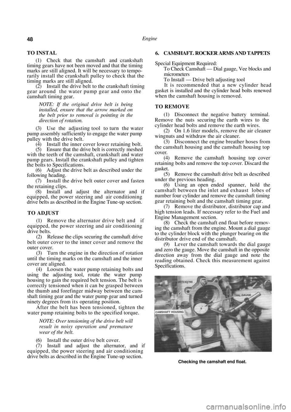
Engine Management section. (8) Check the camshaft end float before remov-
ing the camshaft from the engine. Mount a dial gauge
to the cylinder block with the plunger bearing on the
distributor drive end of the camshaft. (9) Lever the camshaft towards the dial gauge
and zero the gauge. Move the camshaft in the opposite
direction away from the dial gauge and note the
reading obtained. Check this measurement against
Specifications.
Checking the camshaft end float.
Page 49 of 238
Engine 49
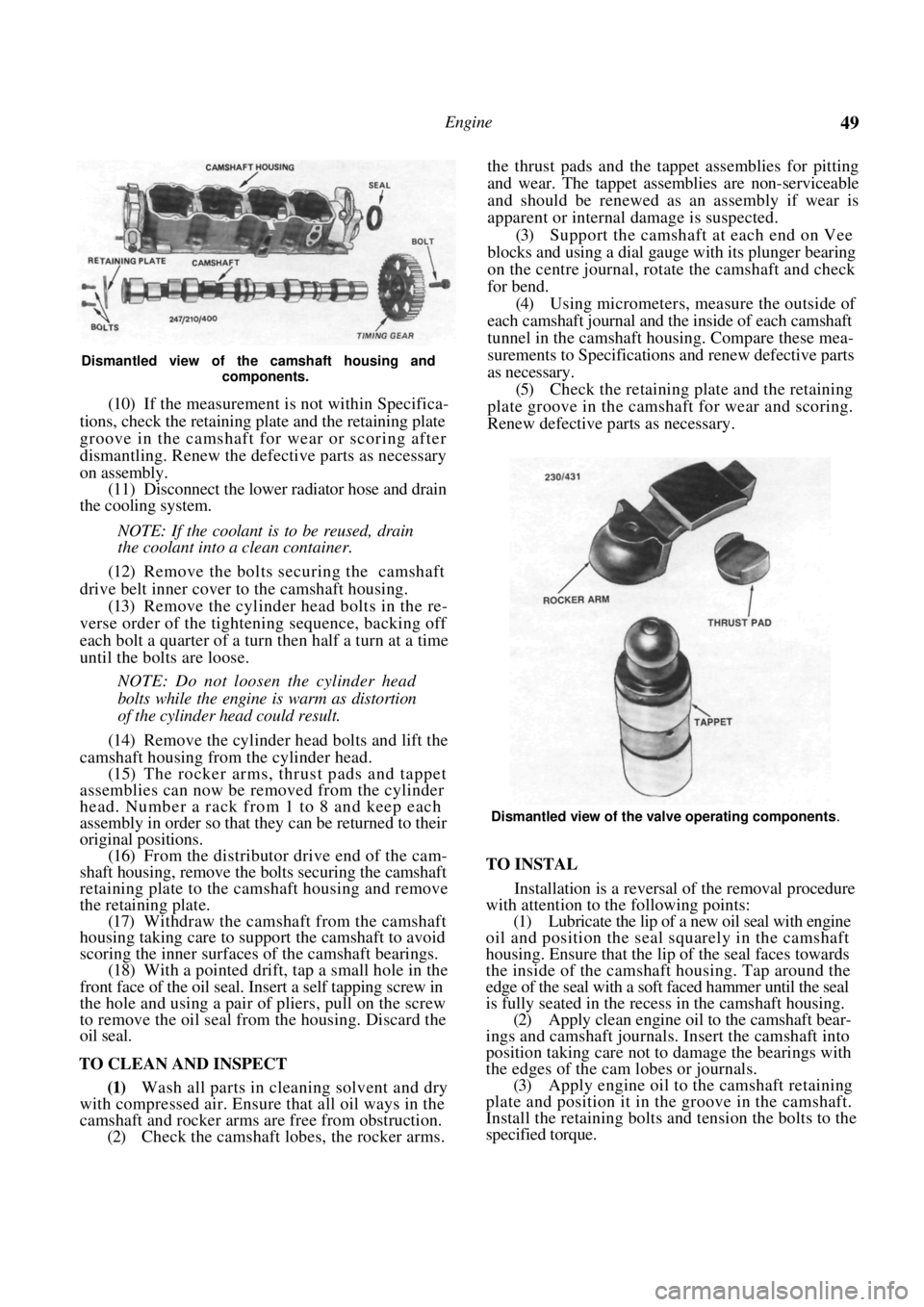
Dismantled view of the camshaft housing and components.
(10) If the measurement is not within Specifica-
tions, check the retaining plate and the retaining plate
groove in the camshaft for wear or scoring after
dismantling. Renew the defective parts as necessary
on assembly. (11) Disconnect the lower radiator hose and drain
the cooling system.
NOTE: If the coolant is to be reused, drain
the coolant into a clean container.
(12) Remove the bolts securing the camshaft
drive belt inner cover to the camshaft housing. (13) Remove the cylinder head bolts in the re-
verse order of the tighten ing sequence, backing off
each bolt a quarter of a turn then half a turn at a time
until the bolts are loose.
NOTE: Do not loosen the cylinder head
bolts while the engine is warm as distortion
of the cylinder head could result.
(14) Remove the cylinder head bolts and lift the
camshaft housing from the cylinder head. (15) The rocker arms, thrust pads and tappet
assemblies can now be removed from the cylinder
head. Number a rack from 1 to 8 and keep each
assembly in order so that they can be returned to their
original positions.
(16) From the distributor drive end of the cam-
shaft housing, remove the bolts securing the camshaft
retaining plate to the camshaft housing and remove
the retaining plate. (17) Withdraw the camshaft from the camshaft
housing taking care to supp ort the camshaft to avoid
scoring the inner surfaces of the camshaft bearings.
(18) With a pointed drift, tap a small hole in the
front face of the oil seal. Insert a self tapping screw in
the hole and using a pair of pliers, pull on the screw
to remove the oil seal from the housing. Discard the
oil seal.
TO CLEAN AND INSPECT
(1) Wash all parts in cleaning solvent and dry
with compressed air. Ensure that all oil ways in the
camshaft and rocker arms are free from obstruction.
(2) Check the camshaft lobes, the rocker arms. the thrust pads and the ta
ppet assemblies for pitting
and wear. The tappet assemblies are non-serviceable
and should be renewed as an assembly if wear is
apparent or internal damage is suspected.
(3) Support the camshaft at each end on Vee
blocks and using a dial gauge with its plunger bearing
on the centre journal, rotate the camshaft and check
for bend. (4) Using micrometers, measure the outside of
each camshaft journal and the inside of each camshaft
tunnel in the camshaft housing. Compare these mea-
surements to Specifications and renew defective parts
as necessary. (5) Check the retaining plate and the retaining
plate groove in the camshaft for wear and scoring.
Renew defective parts as necessary.
Dismantled view of the valve operating components.
TO INSTAL
Installation is a reversal of the removal procedure
with attention to the following points:
(1) Lubricate the lip of a new oil seal with engine
oil and position the seal squarely in the camshaft
housing. Ensure that the li p of the seal faces towards
the inside of the camshaft housing. Tap around the
edge of the seal with a soft faced hammer until the seal
is fully seated in the recess in the camshaft housing. (2) Apply clean engine oil to the camshaft bear-
ings and camshaft journals. Insert the camshaft into
position taking care not to damage the bearings with
the edges of the cam lobes or journals. (3) Apply engine oil to the camshaft retaining
plate and position it in the groove in the camshaft.
Install the retaining bolts and tension the bolts to the
specified torque.
Page 56 of 238
56 Engine
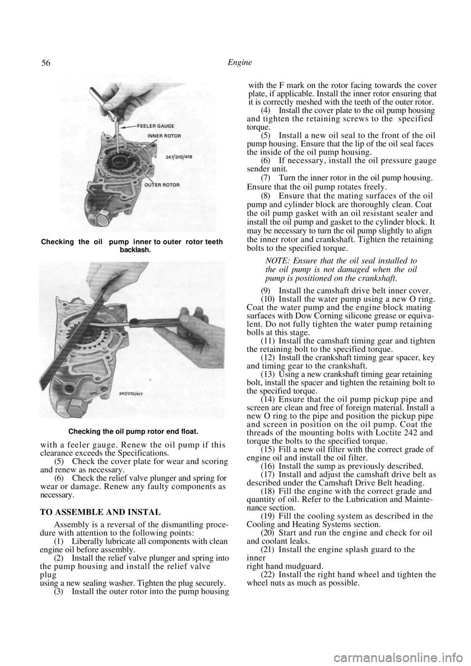
Checking the oil pump rotor end float.
with a feeler gauge. Renew the oil pump if this
clearance exceeds the Specifications.
(5) Check the cover plate for wear and scoring
and renew as necessary. (6) Check the relief valve plunger and spring for
wear or damage. Renew any faulty components as
necessary.
TO ASSEMBLE AND INSTAL
Assembly is a reversal of the dismantling proce-
dure with attention to the following points:
(1) Liberally lubricate all components with clean
engine oil before assembly. (2) Install the relief valve plunger and spring into
the pump housing and install the relief valve
plug
using a new sealing washer. Tighten the plug securely. (3) Install the outer rotor into the pump housing with the F mark on the rotor facing towards the cover
plate, if applicable. Install the inner rotor ensuring that
it is correctly meshed with the teeth of the outer rotor.
(4)
Install the cover plate to the oil pump housing
and tighten the retaining screws to the specified
torque. (5) Install a new oil seal to the front of the oil
pump housing. Ensure that the lip of the oil seal faces
the inside of the oil pump housing. (6) If necessary, install the oil pressure gauge
sender unit.
(7) Turn the inner rotor in the oil pump housing.
Ensure that the oil pump rotates freely. (8) Ensure that the mating surfaces of the oil
pump and cylinder block are thoroughly clean. Coat
the oil pump gasket with an oil resistant sealer and
install the oil pump and gasket to the cylinder block. It
may be necessary to turn the oil pump slightly to align
the inner rotor and crankshaft. Tighten the retaining
bolts to the specified torque.
NOTE: Ensure that the oil seal installed to
the oil pump is not damaged when the oil
pump is positioned on the crankshaft.
(9) Install the camshaft drive belt inner cover.
(10) Install the water pump using a new O ring.
Coat the water pump and the engine block mating
surfaces with Dow Corning silicone grease or equiva-
lent. Do not fully tighten the water pump retaining
bolls at this stage. (11) Install the camshaft timing gear and tighten
the retaining bolt to the specified torque.
(12) Install the crankshaft timing gear spacer, key
and timing gear to the crankshaft. (13) Using a new crankshaft timing gear retaining
bolt, install the spacer and tighten the retaining bolt to
the specified torque. (14) Ensure that the oil pump pickup pipe and
screen are clean and free of foreign material. Install a
new O ring to the pipe and position the pickup pipe
and screen in position on the oil pump. Coat the
threads of the mounting bolts with Loctite 242 and
torque the bolts to the specified torque. (15) Fill a new oil filter with the correct grade of
engine oil and install the oil filter. (16) Install the sump as previously described.
(17) Install and adjust the camshaft drive belt as
described under the Camshaft Drive Belt heading. (18) Fill the engine with the correct grade and
quantity of oil. Refer to the Lubrication and Mainte-
nance section.
(19) Fill the cooling system as described in the
Cooling and Heating Systems section. (20) Start and run the engine and check for oil
and coolant leaks. (21) Install the engine splash guard to the
inner
right hand mudguard. (22) Install the right hand wheel and tighten the
wheel nuts as much as possible.
Checking the oil pump inner to outer rotor teeth
backlash.
Page 60 of 238

60 Engine
NOTE: Should the ring end gap be greater
than the specified gap, another ring set
should be obtained and the ring end gaps
checked and compared with the Specifica-
tions.
(3) Treat each ring and cylinder bore individu-
ally and ensure that the rings are assembled to the
respective piston for the cylinder bore in which they
were installed to check the end gap.
(4) Assemble each oil control ring to its respec-
tive piston bottom groove as follows:
(a) Install the oil ring expander to the
piston
groove, ensuring that the ends of the expander are
bulled together and not overlapped. (b) Position one end of the lower side rail in the
groove and peel the ring over the piston and into the
groove. (c) Similarly install the upper side rail.
(5) Install the lower compression ring into
the
lower piston groove.
NOTE: The compression rings should be
installed with the manufacturers mark fac-
ing the top of the piston. To minimize the
possibility of ring breakage the rings can be
immersed in hot water prior to installation.
(6) Install the upper compression ring into
the
upper piston groove.
(7) Space the compression ring gaps 120 degrees
apart, and ensure that the o il ring gaps and the join in
the oil ring expander are not aligned. (8) With the rings correctly installed and
gapped, remove the bearing cap from the connecting
rod. (9) Liberally lubricate the piston assembly and
install the piston ring compressor to number one
piston.
NOTE: When installing the pistons to the
cylinder ensure that the front marking on
the piston is towards the front of the engine.
(10) Turn the crankshaft until number one crank-
pin is at the bottom of its stroke. (11) Install number one piston and connecting
rod
assembly into its bore. Push the assembly down the
bore until the connecting rod can be aligned with
number one crankpin.
NOTE: The bearing shells should be lubri-
cated with engine oil before installation.
(12) Install the connecting rod cap and tighten
the
retaining bolts to the specified torque.
NOTE: If new bearing shells were installed,
check the bearing clearance with Plastigage
as previously described.
(13) With the bearing clearance as specified, in-
stal the remaining pistons in the same manner.
(14) Ensure that the crankshaft turns without
binding.
(15) With all connecting rod bolts tightened to
the specified torque, install the associated
components
by referring to the relevant headings in this section.
11. CRANKSHAFT AND MAIN BEARINGS
Special Equipment Required:
To Inspect — Micrometer, Vee blocks, dial gauge
TO REMOVE
(1) With the engine assembly removed from the
vehicle and the transaxle separated from the engine,
refer to the appropriate headings or sections and
remove the following components: sump, oil pump
pickup pipe, oil pump, and flywheel or drive plate. (2) Remove the crankshaft rear oil seal from the
Using a ring compressor to install the piston.
Checking the crankshaft end float using feeler gauges.
Page 62 of 238
Engine
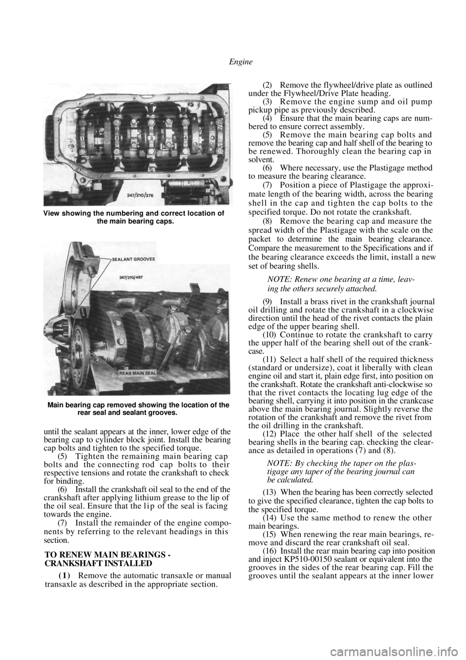
Main bearing cap removed showing the location of the rear seal and sealant grooves.
until the sealant appears at the inner, lower edge of the
bearing cap to cylinder block joint. Install the bearing
cap bolts and tighten to the specified torque.
(5) Tighten the remaining main bearing cap
bolts and the connecting rod cap bolts to their
respective tensions and rotate the crankshaft to check
for binding. (6) Install the crankshaft oil seal to the end of the
crankshaft after applying lithium grease to the lip of
the oil seal. Ensure that the l i p of the seal is facing
towards the engine.
(7) Install the remainder of the engine compo-
nents by referring to the relevant headings in this
section.
TO RENEW MAIN BEARINGS -
CRANKSHAFT INSTALLED
(1) Remove the automatic transaxle or manual
transaxle as described in the appropriate section.
(2) Remove the flywheel/drive plate as outlined
under the Flywheel/Drive Plate heading. (3) Remove the engine sump and oil pump
pickup pipe as previously described. (4) Ensure that the main bearing caps are num-
bered to ensure correct assembly. (5) Remove the main bearing cap bolts and
remove the bearing cap and half shell of the bearing to
be renewed. Thoroughly clean the bearing cap in
solvent. (6) Where necessary, use the Plastigage method
to measure the bearing clearance.
(7) Position a piece of Plastigage the approxi-
mate length of the bearing width, across the bearing
shell in the cap and tigh ten the cap bolts to the
specified torque. Do not rotate the crankshaft. (8) Remove the bearing cap and measure the
spread width of the Plastigage with the scale on the
packet to determine the main bearing clearance.
Compare the measurement to the Specifications and if
the bearing clearance exceeds the limit, install a new
set of bearing shells.
NOTE: Renew one bearing at a time, leav-
ing the others securely attached.
(9) Install a brass rivet in the crankshaft journal
oil drilling and rotate the crankshaft in a clockwise
direction until the head of the rivet contacts the plain
edge of the upper bearing shell. (10) Continue to rotate the crankshaft to carry
the upper half of the bearing shell out of the crank-
case.
(11) Select a half shell of the required thickness
(standard or undersize), coat it liberally with clean
engine oil and start it, plai n edge first, into position on
the crankshaft. Rotate the crankshaft anti-clockwise so
that the rivet contacts the locating lug edge of the
bearing shell, carrying it into position in the crankcase
above the main bearing journal. Slightly reverse the
rotation of the crankshaft and remove the rivet from
the oil drilling in the crankshaft. (12) Place the other half shell of the selected
bearing shells in the bear ing cap. checking the clear-
ance as detailed in operations (7) and (8).
NOTE: By checking the taper on the plas-
tigage any taper of the bearing journal can
be calculated.
(13) When the bearing has been correctly selected
to give the specified clearance, tighten the cap bolts to
the specified torque. (14) Use the same method to renew the other
main bearings. (15) When renewing the rear main bearings, re-
move and discard the rear crankshaft oil seal. (16) Install the rear main bearing cap into position
and inject KP510-00150 sealant or equivalent into the
grooves in the sides of the rear bearing cap. Fill the
grooves until the sealant a ppears at the inner lower
View showing the numbering and correct location of
the main bearing caps.