sensor NISSAN QASHQAI 2017 Owner´s Manual
[x] Cancel search | Manufacturer: NISSAN, Model Year: 2017, Model line: QASHQAI, Model: NISSAN QASHQAI 2017Pages: 508, PDF Size: 2.68 MB
Page 111 of 508
2-32Instruments and controls
Check to see if the sensor area of the front
bumper is blocked. If the sensor area of the front
bumper is blocked, remove the blocking materi-
al. Restart the engine. If the warning light
continues to illuminate, have the Forward
Emergency Braking (FEB) system checked. It
is recommended that you visit a NISSAN dealer
for this service.
For more details, see “Forward Emergency
Braking (FEB)” (P.5-80) , “Forward Emergency
Braking (FEB) with pedestrian detection sys-
tem” (P.5-86) or “Intelligent Cruise Control
(ICC)” (P.5-60) .
37. Unavailable: Side Radar Obstruction
warning (if so equipped)
This warning appears when the Blind Spot
Warning (BSW)/Rear Cross Traffic Alert (RCTA)
system becomes unavailable because a radar
blockage is detected. (See “Blind Spot Warning
(BSW)” (P.5-42) or “Rear Cross Traffic Alert
(RCTA)” (P.5-51) .)
38. Press Brake Pedal warning (for
electronic parking brake equipped mod-
els)
This indicator appears in the following situa-
tions:.The driver tries to release the electronic
parking brake manually without depressing
the brake pedal.
.The vehicle is stopped on a steep hill and
there is a possibility of moving backward,
even if the electronic parking brake is
applied.
Page 115 of 508
2-36Instruments and controls
JVI0932X
CLOCK AND OUTSIDE AIR TEM-
PERATURE
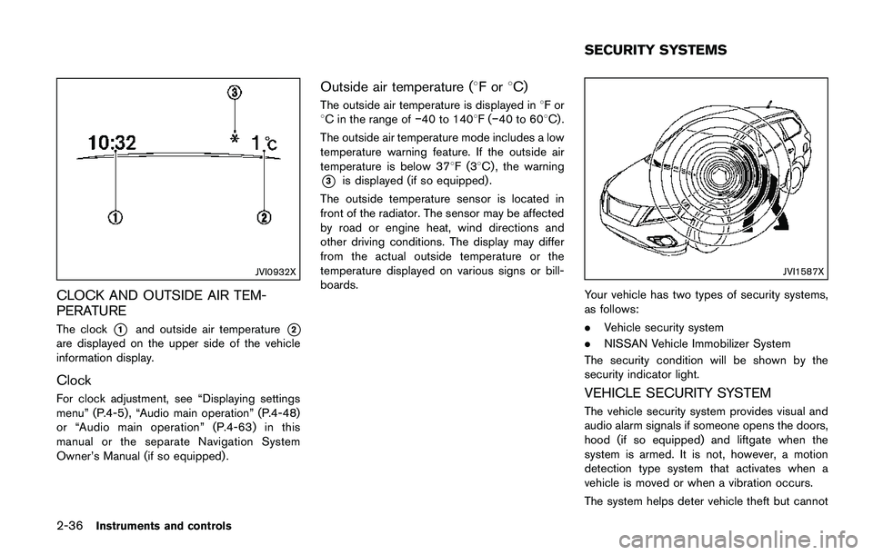
The clock*1and outside air temperature*2
are displayed on the upper side of the vehicle
information display.
Clock
For clock adjustment, see “Displaying settings
menu” (P.4-5) , “Audio main operation” (P.4-48)
or “Audio main operation” (P.4-63) in this
manual or the separate Navigation System
Owner’s Manual (if so equipped) .
Outside air temperature (8For8C)
The outside air temperature is displayed in8For
8C in the range of�í40 to 1408F(�í40 to 608C) .
The outside air temperature mode includes a low
temperature warning feature. If the outside air
temperature is below 378F(38C) , the warning
*3is displayed (if so equipped) .
The outside temperature sensor is located in
front of the radiator. The sensor may be affected
by road or engine heat, wind directions and
other driving conditions. The display may differ
from the actual outside temperature or the
temperature displayed on various signs or bill-
boards.
JVI1587X
Your vehicle has two types of security systems,
as follows:
.Vehicle security system
.NISSAN Vehicle Immobilizer System
The security condition will be shown by the
security indicator light.
VEHICLE SECURITY SYSTEM
The vehicle security system provides visual and
audio alarm signals if someone opens the doors,
hood (if so equipped) and liftgate when the
system is armed. It is not, however, a motion
detection type system that activates when a
vehicle is moved or when a vibration occurs.
The system helps deter vehicle theft but cannot
SECURITY SYSTEMS
Page 123 of 508
2-44Instruments and controls
JVI0510X
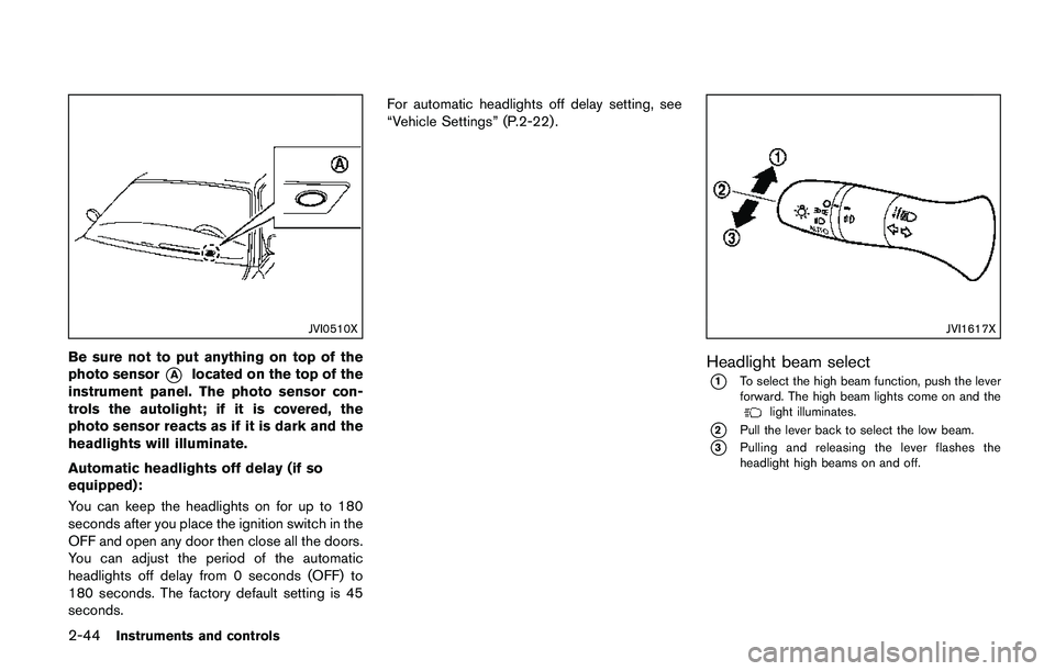
Be sure not to put anything on top of the
photo sensor
*Alocated on the top of the
instrument panel. The photo sensor con-
trols the autolight; if it is covered, the
photo sensor reacts as if it is dark and the
headlights will illuminate.
Automatic headlights off delay (if so
equipped):
You can keep the headlights on for up to 180
seconds after you place the ignition switch in the
OFF and open any door then close all the doors.
You can adjust the period of the automatic
headlights off delay from 0 seconds (OFF) to
180 seconds. The factory default setting is 45
seconds.For automatic headlights off delay setting, see
“Vehicle Settings” (P.2-22) .
JVI1617X
Headlight beam select
*1To select the high beam function, push the lever
forward. The high beam lights come on and the
light illuminates.
*2Pull the lever back to select the low beam.
*3Pulling and releasing the lever flashes the
headlight high beams on and off.
Page 125 of 508
2-46Instruments and controls
JVI1621X
High beam assist operations:
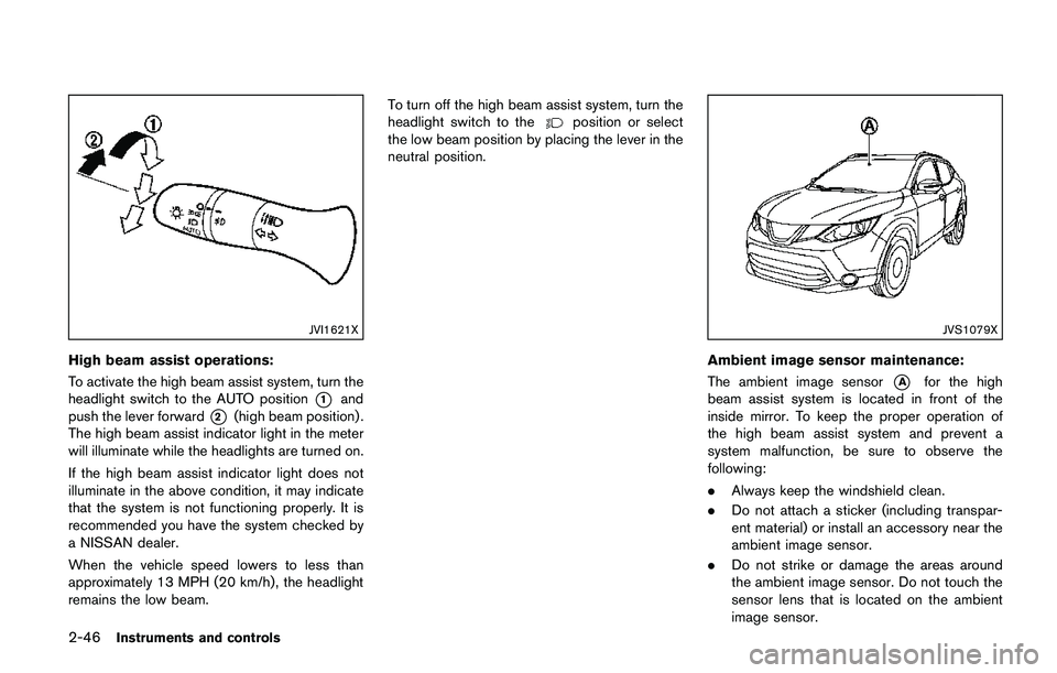
To activate the high beam assist system, turn the
headlight switch to the AUTO position
*1and
push the lever forward
*2(high beam position) .
The high beam assist indicator light in the meter
will illuminate while the headlights are turned on.
If the high beam assist indicator light does not
illuminate in the above condition, it may indicate
that the system is not functioning properly. It is
recommended you have the system checked by
a NISSAN dealer.
When the vehicle speed lowers to less than
approximately 13 MPH (20 km/h) , the headlight
remains the low beam.To turn off the high beam assist system, turn the
headlight switch to the
position or select
the low beam position by placing the lever in the
neutral position.
JVS1079X
Ambient image sensor maintenance:
The ambient image sensor
*Afor the high
beam assist system is located in front of the
inside mirror. To keep the proper operation of
the high beam assist system and prevent a
system malfunction, be sure to observe the
following:
.Always keep the windshield clean.
.Do not attach a sticker (including transpar-
ent material) or install an accessory near the
ambient image sensor.
.Do not strike or damage the areas around
the ambient image sensor. Do not touch the
sensor lens that is located on the ambient
image sensor.
Page 126 of 508
If the ambient image sensor is damaged due to
an accident, it is recommended you contact a
NISSAN dealer.
Battery saver system
.When the headlight switch is in theorposition while the ignition switch is in
the ON position, the lights will automatically
turn off within a period of time after the
ignition switch has been placed in the OFF
position.
.When the headlight switch remains in the
orposition after the lights auto-
matically turn off, the lights will turn on when
the ignition switch is placed in the ON
position.
CAUTION
.When you turn on the headlight
switch again after the lights auto-
matically turn off, the lights will not
turn off automatically. Be sure to
turn the light switch to the OFF
position when you leave the vehicle
for extended periods of time, other-
wise the battery will be discharged.
.Never leave the light switch on
when the engine is not running forextended periods of time even if the
headlights turn off automatically.
Daytime Running Light (DRL) system
The LED portion of the headlights automatically
illuminate at 100% intensity when the engine is
started and the parking brake released. The LED
Daytime Running Light (DRL) operate with the
headlight switch in the OFF position or in the
position. When you turn the headlight
switch to theposition for full illumination,
the LED lights switch from LED DRL to the park
function.
If the parking brake is applied before the engine
is started, the LED DRL do not illuminate. The
LED DRL illuminate when the parking brake is
released. The LED DRL will remain on until the
ignition switch is placed in the OFF position.
It is necessary at dusk to turn the headlight
switch ON for interior controls and switches to
illuminate, as those remain OFF while the switch
is in the OFF position.
WARNING
When the LED DRL system is active, tail
lights on your vehicle are not on. It is
necessary at dusk to turn on yourheadlights. Failure to do so could cause
an accident injuring yourself and
others.
Instruments and controls2-47
Page 218 of 508
JVH0727X
JVH0728X
OPERATING TIPS (for automatic air
conditioner)
When the engine coolant temperature and
outside air temperature are low, the air flow
from the foot outlets may not operate for a
maximum of 150 seconds. However, this is not a
malfunction. After the coolant temperature
warms up, air flow from the foot outlets will
operate normally.
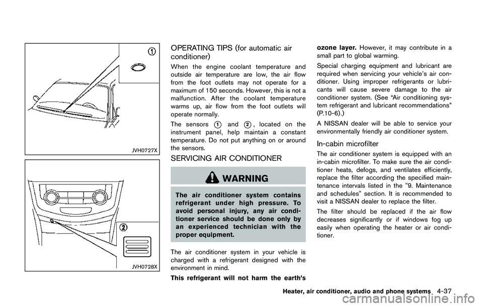
The sensors
*1and*2, located on the
instrument panel, help maintain a constant
temperature. Do not put anything on or around
the sensors.
SERVICING AIR CONDITIONER
WARNING
The air conditioner system contains
refrigerant under high pressure. To
avoid personal injury, any air condi-
tioner service should be done only by
an experienced technician with the
proper equipment.
The air conditioner system in your vehicle is
charged with a refrigerant designed with the
environment in mind.
This refrigerant will not harm the earth’sozone layer.However, it may contribute in a
small part to global warming.
Special charging equipment and lubricant are
required when servicing your vehicle’s air con-
ditioner. Using improper refrigerants or lubri-
cants will cause severe damage to the air
conditioner system. (See “Air conditioning sys-
tem refrigerant and lubricant recommendations”
(P.10-6) .)
A NISSAN dealer will be able to service your
environmentally friendly air conditioner system.
In-cabin microfilter
The air conditioner system is equipped with an
in-cabin microfilter. To make sure the air condi-
tioner heats, defogs, and ventilates efficiently,
replace the filter according the specified main-
tenance intervals listed in the "9. Maintenance
and schedules" section. It is recommended to
visit a NISSAN dealer to replace the filter.
The filter should be replaced if the air flow
decreases significantly or if windows fog up
easily when operating the heater or air condi-
tioner.
Heater, air conditioner, audio and phone systems4-37
Page 292 of 508
for approximately 1 minute. The
light will remain on after 1 minute.
Have your tires replaced and/or
TPMS system reset as soon as
possible. It is recommended you
visit a NISSAN dealer for these
services.
.Replacing tires with those not ori-
ginally specified by NISSAN could
affect the proper operation of the
TPMS.
.Do not inject any tire liquid or
aerosol tire sealant into the tires,
as this may cause a malfunction of
the tire pressure sensors.
CAUTION
.The TPMS may not function properly
when the wheels are equipped with
tire chains or the wheels are buried
in snow.
.Do not place metalized film or any
metal parts (antenna, etc.) on the
windows. This may cause poor re-
ception of the signals from the tire
pressure sensors, and the TPMS willnot function properly.
Some devices and transmitters may temporarily
interfere with the operation of the TPMS and
cause the low tire pressure warning light to
illuminate. Some examples are:
.Facilities or electric devices using similar
radio frequencies are near the vehicle.
.If a transmitter set to similar frequencies is
being used in or near the vehicle.
.If a computer (or similar equipment) or a DC/
AC converter is being used in or near the
vehicle.
Low tire pressure warning light may illuminate in
the following cases.
.If the vehicle is equipped with a wheel and
tire without TPMS.
.If the TPMS has been replaced and the ID
has not been registered.
.If the wheel is not originally specified by
NISSAN.
FCC Notice:
For USA:
This device complies with Part 15 of the
FCC Rules. Operation is subject to the
following two conditions: (1) This device
may not cause harmful interference, and
(2) this device must accept any interfer-ence received, including interference that
may cause undesired operation.
Note: Changes or modifications not ex-
pressly approved by the party responsible
for compliance could void the user’s
authority to operate the equipment.
For Canada:
This device complies with Industry Canada
licence-exempt RSS standard(s) . Opera-
tion is subject to the following two condi-
tions: (1) this device may not cause
interference, and (2) this device must
accept any interference, including interfer-
ence that may cause undesired operation
of the device.
TPMS with Easy Fill Tire Alert
When adding air to an under-inflated tire, the
TPMS with Easy Fill Tire Alert provides visual
and audible signals outside the vehicle to help
you inflate the tires to the recommended COLD
tire pressure.
Vehicle set-up:
1. Park the vehicle in a safe and level place.
2. Apply the parking brake and place the shift
lever in the P (Park) position (CVT model) or
N (Neutral) position (MT model) .
Starting and driving5-7
Page 327 of 508

5-42Starting and driving
WARNING
Failure to follow the warnings and
instructions for proper use of the BSW
system could result in serious injury or
death.
.The BSW system is not a replace-
ment for proper driving procedure
and is not designed to prevent
contact with vehicles or objects.
When changing lanes, always use
the side and rear mirrors and turn
and look in the direction your vehi-
cle will move to ensure it is safe to
change lanes. Never rely solely on
the BSW system.
The BSW system helps alert the driver of other
vehicles in adjacent lanes when changing lanes.
JVS0649X
The BSW system uses radar sensors*1
installed near the rear bumper to detect other
vehicles in an adjacent lane.
SSD1030
Detection zone
The radar sensors can detect vehicles on either
side of your vehicle within the detection zone
shown as illustrated. This detection zone starts
from the outside mirror of your vehicle and
extends approximately 10 ft (3.0 m) behind the
rear bumper, and approximately 10 ft (3.0 m)
sideways.
BLIND SPOT WARNING (BSW) (if so
equipped)
Page 328 of 508

JVS1091X
*1Side indicator light
*2Vehicle information display
*3Steering-wheel-mounted controls (left side)
*4Blind Spot Warning (BSW) switch (for models
without LDP system)
BSW SYSTEM OPERATION
The BSW system operates above approximately
20 MPH (32 km/h) .
If the radar sensors detect a vehicle in the
detection zone, the side indicator light
*1
illuminates.If the turn signal is then activated, the system
chimes (twice) and the side indicator light
flashes. The side indicator light continues to
flash until the detected vehicle leaves the
detection zone.
The side indicator light illuminates for a few
seconds when the ignition switch is placed in
the ON position.
The brightness of the side indicator light is
adjusted automatically depending on the bright-
ness of the ambient light.
If a vehicle comes into the detection zone after
the driver activates the turn signal, then only the
side indicator light flashes and no chime sounds.
For additional information, refer to “BSW driving
situations” (P.5-46).
Starting and driving5-43
Page 330 of 508

BSW SYSTEM LIMITATIONS
WARNING
Listed below are the system limitations
for the BSW system. Failure to operate
the vehicle in accordance with these
system limitations could result in ser-
ious injury or death.
.The BSW system cannot detect all
vehicles under all conditions.
.The radar sensors may not be able
to detect and activate BSW when
certain objects are present such as:
— Pedestrians, bicycles, animals.
— Vehicles such as motorcycles,
low height vehicles, or high
ground clearance vehicles.
— Oncoming vehicles.
— Vehicles remaining in the detec-
tion zone when you accelerate
from a stop.
— A vehicle merging into an adja-
cent lane at a speed approxi-
mately the same as your vehicle.— A vehicle approaching rapidly
from behind.
— A vehicle which your vehicle
overtakes rapidly.
— A vehicle that passes through
the detection zone quickly.
— When overtaking several vehi-
cles in a row, the vehicles after
the first vehicle may not be
detected if they are traveling
close together.
.The radar sensor’s detection zone is
designed based on a standard lane
width. When driving in a wider lane,
the radar sensors may not detect
vehicles in an adjacent lane. When
driving in a narrow lane, the radar
sensors may detect vehicles driving
two lanes away.
.The radar sensors are designed to
ignore most stationary objects,
however objects such as guardrails,
walls, foliage and parked vehicles
may occasionally be detected. This
is a normal operation condition.
.The following conditions may re-
duce the ability of the radar to
detect other vehicles:— Severe weather
— Road spray
— Ice/frost/dirt build-up on the
vehicle
.Do not attach stickers (including
transparent material) , install acces-
sories or apply additional paint near
the radar sensors. These conditions
may reduce the ability of the radar
to detect other vehicles.
.Excessive noise (for example, audio
system volume, open vehicle win-
dow) will interfere with the chime
sound, and it may not be heard.
Starting and driving5-45