change wheel NISSAN QASHQAI 2017 Owner´s Manual
[x] Cancel search | Manufacturer: NISSAN, Model Year: 2017, Model line: QASHQAI, Model: NISSAN QASHQAI 2017Pages: 508, PDF Size: 2.68 MB
Page 70 of 508
This may be due to the following conditions that
may be interfering with the weight sensors:
.Small adult or child is not sitting upright,
leaning against the seatback, and centered
on the seat cushion with his/her feet
comfortably extended to the floor.
.The child restraint is not properly installed,
as outlined. (See “Child restraints” (P.1-
19) .)
.An object weighing over 9.1 lbs (4 kg)
hanging on the seat or placed in the
seatback pocket.
.A child restraint or other object pressing
against the rear of the seatback.
.A rear passenger pushing or pulling on the
back of the front passenger seat.
.Forcing the front seat or seatback against an
object on the seat or floor behind it.
.An object placed under the front passenger
seat.
.An object placed between the seat cushion
and center console.
.The front passenger seat head restraint
contacting the roof.
If the vehicle is moving, please come to a stop
when it is safe to do so. Check and correct any
of the above conditions. Restart the vehicle and
wait 1 minute.NOTE:
A system check will be performed during
which the front passenger air bag status
light will remain lit for about 7 seconds
initially.
If the light is still OFF after this, the small adult,
child or child restraint should be repositioned in
the rear seat and it is recommended that the
vehicle should be checked by a NISSAN dealer
as soon as possible.
3. If the light is OFF with no front passenger and no
objects on the front passenger seat, the vehicle
should be checked as soon as possible. It is
recommended you visit a NISSAN dealer for this
service.
Other supplemental front-impact air bag
precautions
WARNING
.Do not place any objects on the
steering wheel pad or on the instru-
ment panel. Also, do not place any
objects between any occupant and
the steering wheel or instrument
panel. Such objects may become
dangerous projectiles and cause
injury if the front air bags inflate..Do not place objects with sharp
edges on the seat. Also, do not
place heavy objects on the seat that
will leave permanent impressions in
the seat. Such objects can damage
the seat or occupant classification
sensors (weight sensors) . This can
affect the operation of the air bag
system and result in serious perso-
nal injury.
.Do not use water or acidic cleaners
(hot steam cleaners) on the seat.
This can damage the seat or occu-
pant classification sensors. This can
also affect the operation of the air
bag system and result in serious
personal injury.
.Immediately after inflation, several
front air bag system components
will be hot. Do not touch them; you
may severely burn yourself.
.No unauthorized changes should be
made to any components or wiring
of the supplemental air bag system.
This is to prevent accidental infla-
tion of the supplemental air bag or
damage to the supplemental air bag
system.
Safety — Seats, seat belts and supplemental restraint system1-51
Page 71 of 508
1-52Safety — Seats, seat belts and supplemental restraint system
.Do not make unauthorized changes
to your vehicle’s electrical system,
suspension system or front end
structure. This could affect proper
operation of the front air bag sys-
tem.
.Tampering with the front air bag
system may result in serious perso-
nal injury. Tampering includes
changes to the steering wheel and
the instrument panel assembly by
placing material over the steering
wheel pad and above the instrument
panel or by installing additional trim
material around the air bag system.
.Removing or modifying the front
passenger seat may affect the func-
tion of the air bag system and result
in serious personal injury.
.Modifying or tampering with the
front passenger seat may result in
serious personal injury. For exam-
ple, do not change the front seats by
placing material on the seat cushion
or by installing additional trim ma-
terial, such as seat covers, on the
seat that is not specifically designed
to assure proper air bag operation.
Additionally, do not stow any ob-jects under the front passenger seat
or the seat cushion and seatback.
Such objects may interfere with the
proper operation of the occupant
classification sensors.
.No unauthorized changes should be
made to any components or wiring
of the seat belt system. This may
affect the front air bag system.
Tampering with the seat belt system
may result in serious personal in-
jury.
.It is recommended you visit a
NISSAN dealer for work on and
around the front air bag. It is also
recommended you visit a NISSAN
dealer for installation of electrical
equipment. The Supplemental Re-
straint System (SRS) wiring har-
nesses* should not be modified or
disconnected. Unauthorized electri-
cal test equipment and probing
devices should not be used on the
air bag system.
.A cracked windshield should be
replaced immediately by a qualified
repair facility. A cracked windshield
could affect the function of thesupplemental air bag system.
*The SRS wiring harness connectors are
yellow and orange for easy identification.
When selling your vehicle, we request that you
inform the buyer about the front air bag system
and guide the buyer to the appropriate sections
in this Owner’s Manual.
Page 98 of 508
.Indicators and warnings
.Tire pressure information
.Chassis Control
.Other information
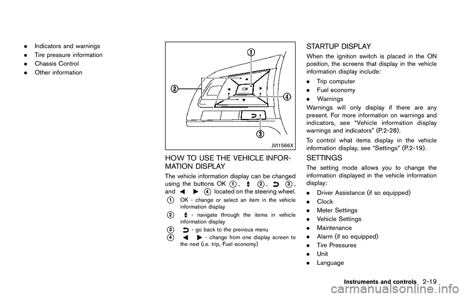
JVI1566X
HOW TO USE THE VEHICLE INFOR-
MATION DISPLAY
The vehicle information display can be changed
using the buttons OK
*1,*2,*3,
and
*4located on the steering wheel.
*1OK - change or select an item in the vehicle
information display
*2- navigate through the items in vehicle
information display
*3- go back to the previous menu
*4- change from one display screen to
the next (i.e. trip, Fuel economy)
STARTUP DISPLAY
When the ignition switch is placed in the ON
position, the screens that display in the vehicle
information display include:
.Trip computer
.Fuel economy
.Warnings
Warnings will only display if there are any
present. For more information on warnings and
indicators, see “Vehicle information display
warnings and indicators” (P.2-28) .
To control what items display in the vehicle
information display, see “Settings” (P.2-19) .
SETTINGS
The setting mode allows you to change the
information displayed in the vehicle information
display:
.Driver Assistance (if so equipped)
.Clock
.Meter Settings
.Vehicle Settings
.Maintenance
.Alarm (if so equipped)
.Tire Pressures
.Unit
.Language
Instruments and controls2-19
Page 103 of 508
2-24Instruments and controls
checking or replacing these items. For sched-
uled maintenance items and intervals, refer to
the “9. Maintenance and schedules” section.
Tire:
This indicator appears when the customer set
distance comes for replacing tires. You can set
or reset the distance for replacing tires.
WARNING
The tire replacement indicator is not a
substitute for regular tire checks, in-
cluding tire pressure checks. See
“Changing wheels and tires”(P.8-37) .
Many factors including tire inflation,
alignment, driving habits and road con-
ditions affect tire wear and when tires
should be replaced. Setting the tire
replacement indicator for a certain
driving distance does not mean your
tires will last that long. Use the tire
replacement indicator as a guide only
and always perform regular tire checks.
Failure to perform regular tire checks,
including tire pressure checks could
result in tire failure. Serious vehicle
damage could occur and may lead to a
collision, which could result in serious
personal injury or death.Other:
This indicator appears when the customer set
distance comes for checking or replacing
maintenance items other than the engine oil, oil
filter and tires. Other maintenance items can
include such things as air filter or tire rotation.
You can set or reset the distance for checking or
replacing the items.
Alarm (if so equipped)
This setting allows the customer to set alarms.
Select “Alarm” using the
button*2and
press OK button
*1.
Timer Alert (if so equipped):
This setting allows the customer to set an alert
to notify the driver that the set time has been
reached.
1. Use the
button*2to select “Timer
Alert”.
2. Press the OK button
*1.
3. To change the timer amount, use the
button*2and the OK button*1to save
the selected time amount.
Navigation (if so equipped):
This setting allows the customer to enable/
disable the alert for navigation in the vehicle
information display.1. Use the
button*2to select “Naviga-
tion”.
2. Press the OK button
*1to turn ON/OFF
the alert.
Phone (if so equipped):
This setting allows the customer to enable/
disable the alert for an incoming call in the
vehicle information display.
1. Use the
button*2to select “Phone”.
2. Press the OK button
*1to turn ON/OFF
the alert.
Mail (if so equipped):
This setting allows the customer to enable/
disable the alert for navigation in the vehicle
information display.
1. Use the
button*2to select “Mail”.
2. Press the OK button
*1to turn ON/OFF
the alert.
Page 108 of 508
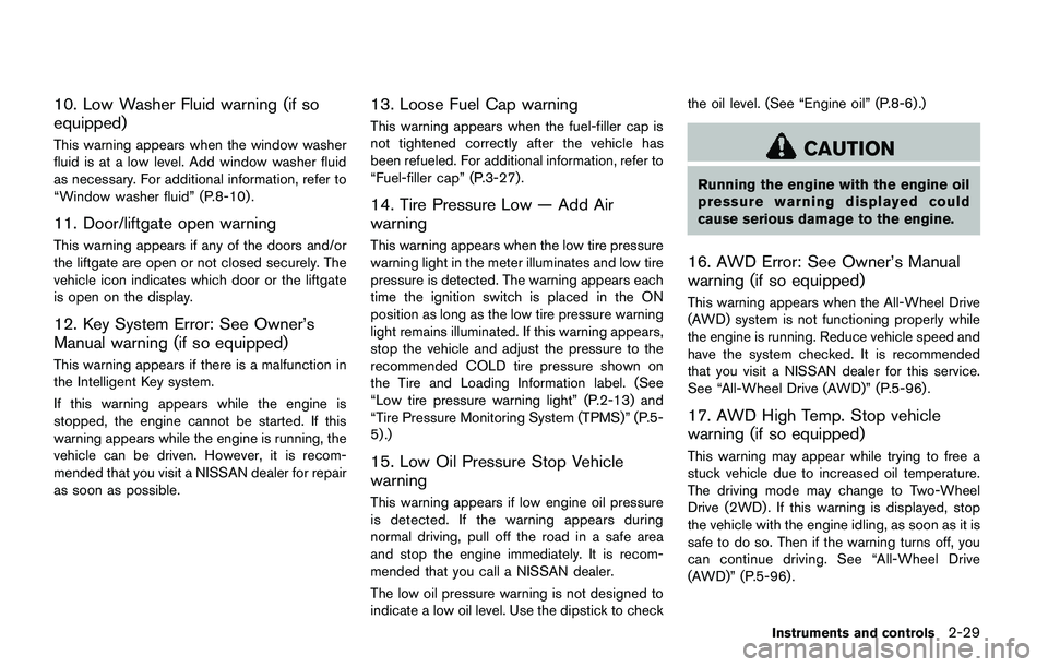
10. Low Washer Fluid warning (if so
equipped)
This warning appears when the window washer
fluid is at a low level. Add window washer fluid
as necessary. For additional information, refer to
“Window washer fluid” (P.8-10) .
11. Door/liftgate open warning
This warning appears if any of the doors and/or
the liftgate are open or not closed securely. The
vehicle icon indicates which door or the liftgate
is open on the display.
12. Key System Error: See Owner’s
Manual warning (if so equipped)
This warning appears if there is a malfunction in
the Intelligent Key system.
If this warning appears while the engine is
stopped, the engine cannot be started. If this
warning appears while the engine is running, the
vehicle can be driven. However, it is recom-
mended that you visit a NISSAN dealer for repair
as soon as possible.
13. Loose Fuel Cap warning
This warning appears when the fuel-filler cap is
not tightened correctly after the vehicle has
been refueled. For additional information, refer to
“Fuel-filler cap” (P.3-27) .
14. Tire Pressure Low — Add Air
warning
This warning appears when the low tire pressure
warning light in the meter illuminates and low tire
pressure is detected. The warning appears each
time the ignition switch is placed in the ON
position as long as the low tire pressure warning
light remains illuminated. If this warning appears,
stop the vehicle and adjust the pressure to the
recommended COLD tire pressure shown on
the Tire and Loading Information label. (See
“Low tire pressure warning light” (P.2-13) and
“Tire Pressure Monitoring System (TPMS)” (P.5-
5) .)
15. Low Oil Pressure Stop Vehicle
warning
This warning appears if low engine oil pressure
is detected. If the warning appears during
normal driving, pull off the road in a safe area
and stop the engine immediately. It is recom-
mended that you call a NISSAN dealer.
The low oil pressure warning is not designed to
indicate a low oil level. Use the dipstick to checkthe oil level. (See “Engine oil” (P.8-6) .)
CAUTION
Running the engine with the engine oil
pressure warning displayed could
cause serious damage to the engine.
16. AWD Error: See Owner’s Manual
warning (if so equipped)
This warning appears when the All-Wheel Drive
(AWD) system is not functioning properly while
the engine is running. Reduce vehicle speed and
have the system checked. It is recommended
that you visit a NISSAN dealer for this service.
See “All-Wheel Drive (AWD)” (P.5-96) .
17. AWD High Temp. Stop vehicle
warning (if so equipped)
This warning may appear while trying to free a
stuck vehicle due to increased oil temperature.
The driving mode may change to Two-Wheel
Drive (2WD) . If this warning is displayed, stop
the vehicle with the engine idling, as soon as it is
safe to do so. Then if the warning turns off, you
can continue driving. See “All-Wheel Drive
(AWD)” (P.5-96) .
Instruments and controls2-29
Page 124 of 508
High beam assist (if so equipped)
The high beam assist system will operate when
the vehicle is driven at speeds of approximately
19 MPH (30 km/h) and above. If an oncoming
vehicle or leading vehicle appears in front of your
vehicle when the headlight high beam is on, the
headlight will be switched to the low beam
automatically.
Precautions on high beam assist:
WARNING
.The high beam assist system is a
convenience but it is not a substi-
tute for safe driving operation. The
driver should remain alert at all
times, ensure safe driving practices
and switch the high beams and low
beam manually when necessary.
.The high beam or low beam may not
switch automatically under the fol-
lowing conditions. Switch the high
beam and low beam manually.
— During bad weather (rain, fog,
snow, wind, etc.) .
— When a light source similar to a
headlight or tail light is in the
vicinity of the vehicle.— When the headlights of the
oncoming vehicle or the leading
vehicle are turned off, when the
color of the light is affected due
to foreign materials on the
lights, or when the light beam
is out of position.
— When there is a sudden, contin-
uous change in brightness.
— When driving on a road that
passes over rolling hills, or a
road that has level differences.
— When driving on a road with
many curves.
— When a sign or mirror-like sur-
face is reflecting intense light
towards the front of the vehicle.
— When the container, etc. being
towed by a leading vehicle is
reflecting intense light.
— When a headlight on your vehi-
cle is damaged or dirty.
— When the vehicle is leaning at
an angle due to a punctured tire,
being towed, etc..The timing of switching the low
beam and high beam may change
under the following situations.
— The brightness of the headlights
of the oncoming vehicle or lead-
ing vehicle.
— The movement and direction of
the oncoming vehicle and the
leading vehicle.
— When only one light on the
oncoming vehicle or the leading
vehicle is illuminated.
— When the oncoming vehicle or
the leading vehicle is a two-
wheeled vehicle.
— Road conditions (incline, curve,
the road surface, etc.) .
— The number of passengers and
the amount of cargo.
Instruments and controls2-45
Page 217 of 508

4-36Heater, air conditioner, audio and phone systems
sponding temperature control dial.
Also turning the passenger’s side tempera-
ture control dial changes only the front
passenger’s side temperature. (The DUAL
indicator light will illuminate and DUAL will
appear on the display.)
.To cancel the separate temperature setting,
push the DUAL button (the indicator light
will turn off) and the driver’s side tempera-
ture setting will be applied to both the driver
and passenger sides.
Air intake control:
.Push the air recirculation
button to
recirculate interior air inside the vehicle. The
indicator light on the button will come on.
The air recirculation cannot be activated
when the air conditioner is in the front
defrosting mode.
.Push the outside air circulation
button
to draw outside air into the passenger
compartment. The indicator light on the
button will come on.
.To control the air intake automatically, push
and hold either the air recirculation
button or the outside air circulationbutton (whichever button with the indicator
light illuminated) . The indicator lights (both
air recirculation
and outside air circula-
tionbuttons) will flash twice, and thenthe air intake will switch to automatic control.
When the automatic control is set, the
system automatically alternates between
the outside air circulation and the air
recirculation modes. (The indicator light of
the active mode will turn on.)
NOTE:
Even if the system is manually set to the air
recirculation mode, when both outside
temperature and coolant temperature are
low, the system may automatically switch
to the outside air circulation mode.
To turn the system off:
To turn off the heater and air conditioner, push
the ON·OFF button.
Push the ON·OFF button again, the system will
turn on in the mode which was used immediately
before the system was turned off.
Remote engine start logic (if so
equipped)
When the remote engine start function is
activated, the vehicles equipped with the auto-
matic air conditioner and heater may go into
automatic heating or cooling mode depending
on the outside and cabin temperatures. During
this period, the display and the buttons will be
inoperable until the ignition switch is placed in
the ON position. When the temperature is low,the rear defroster and the heated steering wheel
(if so equipped) may also be activated auto-
matically with the activation of the remote engine
start function. (See “Remote engine start” (P.3-
22) .)
Page 259 of 508
4-78Heater, air conditioner, audio and phone systems
GENERAL INFORMATION
Apple Siri�ŠEyes Free personal assistant can be
accessed from the vehicle. Siri�ŠEyes Free can
be accessed in Siri�ŠEyes Free mode to reduce
user distraction. In this mode, Siri�ŠEyes Free is
available for interaction by voice control. After
connecting a compatible Apple device by using
Bluetooth
�Š, Siri�ŠEyes Free can be activated
using thebutton on the steering wheel.
Siri�Šis a trademark of Apple Inc., registered in
the U.S. and other countries.
INFO:
.Some Siri
�ŠEyes Free functions, such as
opening apps, may not be available during
driving.
.For best results, always update your device
to the latest software version.
.Keep the interior of the vehicle as quiet as
possible. Close the windows to eliminate the
surrounding noises (traffic noises, vibration
sounds, etc.) , which may prevent the system
from recognizing the voice commands cor-
rectly.
.For functions that can be used in Siri
�ŠEyes
Free, please refer to the Apple website.
REQUIREMENTS
Siri�Šis available on the iPhone�Š4S or later.
Devices released before iPhone�Š4S are not
supported by the Siri�ŠEyes Free system.
Visit www.apple.com/ios/siri for details about
device compatibility.
Siri
�Šmust be enabled on the phone. Please
check phone settings.
If the device has a lock screen, Siri
�Šmust be
accessible from the lock screen. Please check
phone settings.
For best results, always update your device to
the latest software version.
JVH1592X
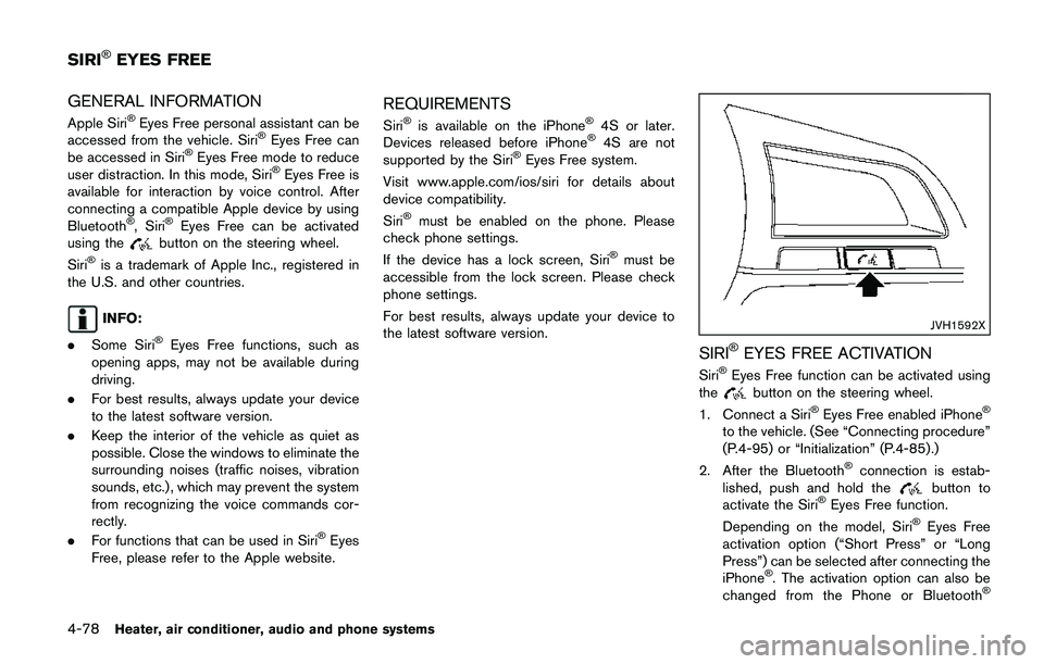
SIRI�ŠEYES FREE ACTIVATION
Siri�ŠEyes Free function can be activated using
thebutton on the steering wheel.
1. Connect a Siri�ŠEyes Free enabled iPhone�Š
to the vehicle. (See “Connecting procedure”
(P.4-95) or “Initialization” (P.4-85) .)
2. After the Bluetooth
�Šconnection is estab-
lished, push and hold thebutton to
activate the Siri�ŠEyes Free function.
Depending on the model, Siri�ŠEyes Free
activation option (“Short Press” or “Long
Press”) can be selected after connecting the
iPhone
�Š. The activation option can also be
changed from the Phone or Bluetooth�Š
SIRI�ŠEYES FREE
Page 262 of 508
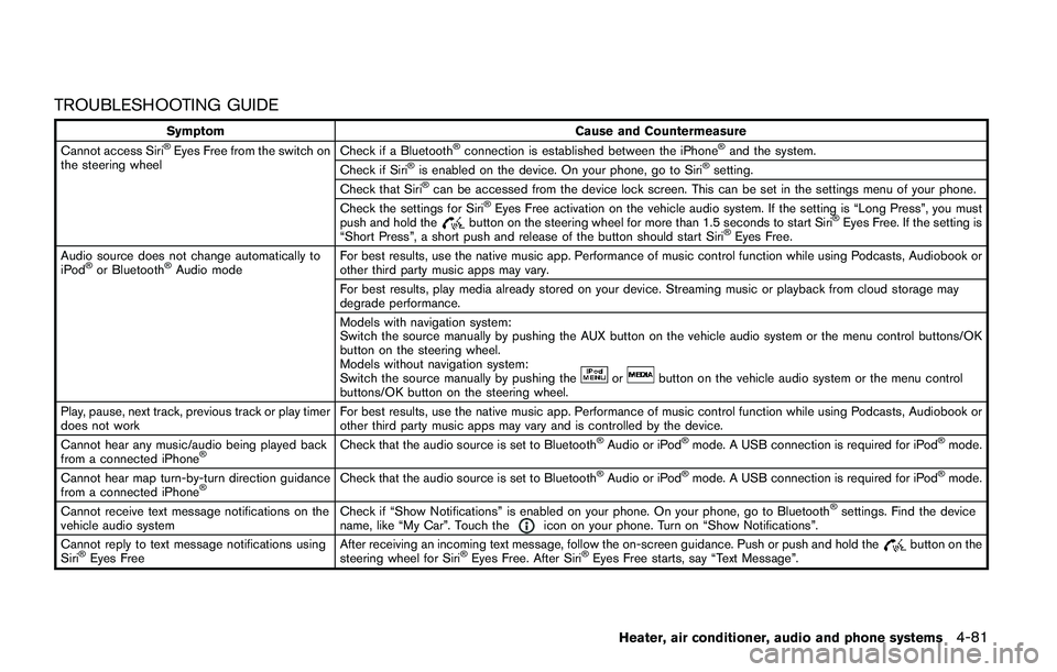
TROUBLESHOOTING GUIDE
Symptom Cause and Countermeasure
Cannot access Siri�ŠEyes Free from the switch on
the steering wheelCheck if a Bluetooth�Šconnection is established between the iPhone�Šand the system.
Check if Siri�Šis enabled on the device. On your phone, go to Siri�Šsetting.
Check that Siri�Šcan be accessed from the device lock screen. This can be set in the settings menu of your phone.
Check the settings for Siri�ŠEyes Free activation on the vehicle audio system. If the setting is “Long Press”, you must
push and hold thebutton on the steering wheel for more than 1.5 seconds to start Siri�ŠEyes Free. If the setting is
“Short Press”, a short push and release of the button should start Siri�ŠEyes Free.
Audio source does not change automatically to
iPod
�Šor Bluetooth�ŠAudio modeFor best results, use the native music app. Performance of music control function while using Podcasts, Audiobook or
other third party music apps may vary.
For best results, play media already stored on your device. Streaming music or playback from cloud storage may
degrade performance.
Models with navigation system:
Switch the source manually by pushing the AUX button on the vehicle audio system or the menu control buttons/OK
button on the steering wheel.
Models without navigation system:
Switch the source manually by pushing the
orbutton on the vehicle audio system or the menu control
buttons/OK button on the steering wheel.
Play, pause, next track, previous track or play timer
does not workFor best results, use the native music app. Performance of music control function while using Podcasts, Audiobook or
other third party music apps may vary and is controlled by the device.
Cannot hear any music/audio being played back
from a connected iPhone
�ŠCheck that the audio source is set to Bluetooth�ŠAudio or iPod�Šmode. A USB connection is required for iPod�Šmode.
Cannot hear map turn-by-turn direction guidance
from a connected iPhone
�ŠCheck that the audio source is set to Bluetooth�ŠAudio or iPod�Šmode. A USB connection is required for iPod�Šmode.
Cannot receive text message notifications on the
vehicle audio systemCheck if “Show Notifications” is enabled on your phone. On your phone, go to Bluetooth
�Šsettings. Find the device
name, like “My Car”. Touch theicon on your phone. Turn on “Show Notifications”.
Cannot reply to text message notifications using
Siri
�ŠEyes FreeAfter receiving an incoming text message, follow the on-screen guidance. Push or push and hold thebutton on the
steering wheel for Siri�ŠEyes Free. After Siri�ŠEyes Free starts, say “Text Message”.
Heater, air conditioner, audio and phone systems4-81
Page 266 of 508
The manual control mode does not allow dialing
a phone number by digits. The user may select
an entry from the Phonebook or Recent Calls
lists. To reactivate Voice Recognition, exit the
manual control mode by pushing and holding the
button. At that time, pushing thebutton
will start the Bluetooth�ŠHands-Free Phone
System.
Choosing a language
You can interact with the Bluetooth�ŠHands-
Free Phone System using several languages
that are available. For operations to change the
language, see “Audio main operation” (P.4-48)
or “Audio main operation” (P.4-56) .
Changing voice feedback volume
If you want to adjust the volume of the voice
feedback, push the volume control buttons on
the steering wheel while being provided with
feedback. You can also use the Power/VOL dial
on the control panel.
Initialization
When the ignition switch is placed in the ACC
or ON position, voice recognition is initialized,
which takes a few seconds. If the
button is
pushed before the initialization completes, the
system will announce “Hands-free phone sys-
tem not ready” and will not react to voice
commands.
Connecting procedure:
NOTE:
The connecting procedure must be per-
formed when the vehicle is stationary. If
the vehicle starts moving during the pro-
cedure, the procedure will be cancelled.
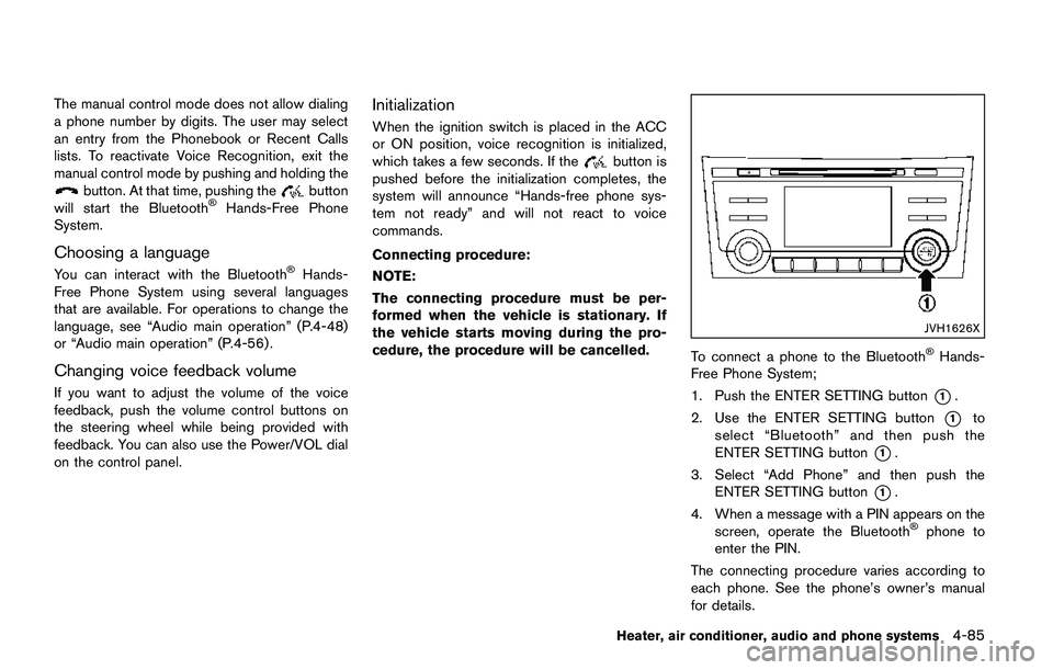
JVH1626X
To connect a phone to the Bluetooth�ŠHands-
Free Phone System;
1. Push the ENTER SETTING button
*1.
2. Use the ENTER SETTING button
*1to
select “Bluetooth” and then push the
ENTER SETTING button
*1.
3. Select “Add Phone” and then push the
ENTER SETTING button
*1.
4. When a message with a PIN appears on the
screen, operate the Bluetooth
�Šphone to
enter the PIN.
The connecting procedure varies according to
each phone. See the phone’s owner’s manual
for details.
Heater, air conditioner, audio and phone systems4-85