NISSAN QUEST 2000 V41 / 2.G Owners Manual
Manufacturer: NISSAN, Model Year: 2000, Model line: QUEST, Model: NISSAN QUEST 2000 V41 / 2.GPages: 292, PDF Size: 2.48 MB
Page 111 of 292
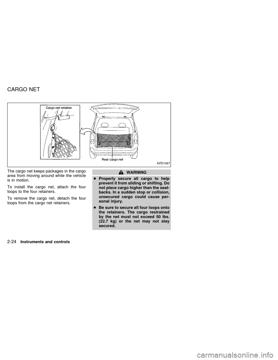
The cargo net keeps packages in the cargo
area from moving around while the vehicle
is in motion.
To install the cargo net, attach the four
loops to the four retainers.
To remove the cargo net, detach the four
loops from the cargo net retainers.WARNING
cProperly secure all cargo to help
prevent it from sliding or shifting. Do
not place cargo higher than the seat-
backs. In a sudden stop or collision,
unsecured cargo could cause per-
sonal injury.
cBe sure to secure all four loops onto
the retainers. The cargo restrained
by the net must not exceed 50 lbs.
(22.7 kg) or the net may not stay
secured.
APD1067
CARGO NET
2-24Instruments and controls
ZX
Page 112 of 292
WARNING
cBefore using the parcel shelf, the
three-passenger bench seat must be
in the third row position, and theseat back must be upright.
cAfter adjusting the parcel shelf to the
desired height, make sure the lock
knob is securely latched.cProperly secure all packages under
the parcel shelf net to prevent them
from sliding or shifting. Do not place
packages higher than the three-
passenger bench seat back. In a
sudden stop or collision, unsecured
packages could cause personal in-
jury.
cBe sure to secure all three parcel
shelf net loops onto the retainers
located on the bottom side of the
parcel shelf. The packages placed
on the parcel shelf and restrained by
the parcel shelf net must not exceed
30 pounds (13.6 kg), or the parcel
shelf may not remain secure.
cDo not allow people or pets on or
under the parcel shelf.
cThe parcel shelf must be removed
from the vehicle if installing a child
restraint on the three-passenger
bench seat that requires the use of a
top tether strap that is anchored to
the vehicle floor. Failure to remove
the parcel shelf can increase the
severity of injury to the child in an
accident.
APD1071
PARCEL SHELF (if so
equipped)
Instruments and controls2-25
ZX
Page 113 of 292

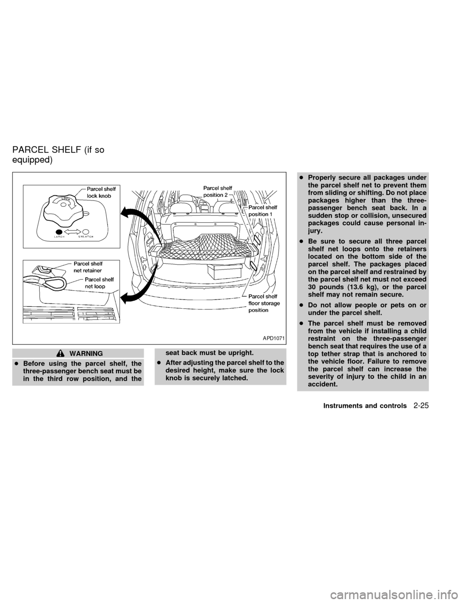
The parcel shelf allows for additional stor-
age for packages.
Do not load more than 30 pounds (13.6 kg)
on the parcel shelf. The parcel shelf can be
installed at two different heights and in a
storage position.
To install the parcel shelf:
c
Position the right side of the parcel shelf
in to one of the shelf positions on the right
side luggage compartment trim panel.
cPosition the left side of the parcel shelf
into the matching position (same height)
on the left side luggage compartment trim
panel.
cSlide the parcel shelf lock knob fully to
the left side (latch in green dot position).
cTurn the parcel shelf lock knob clock-
wise until securely locked.
The parcel shelf is also equipped with a
parcel shelf net to keep packages on the
parcel shelf from moving around while the
vehicle is in motion.
The parcel shelf net is permanently at-
tached to the back side of the parcel shelf.
Pull the parcel shelf net over the packagesand attach the three loops to the three
retainers on the bottom side of the parcel
shelf. Make sure the parcel shelf is securely
locked before covering the packages with
the parcel shelf net.
To remove the parcel shelf:
cUnlock the parcel shelf net.
cRemove all packages from the parcel
shelf.
cTurn the parcel shelf lock knob counter
clockwise until loose (maximum two
turns).
cSlide the parcel shelf lock knob fully to
the right side (unlatch in red dot posi-
tion).
cRemove the parcel shelf from the left
side luggage compartment trim panel,
then the right side luggage compartment
trim panel and reposition the parcel shelf
where desired.Put the parcel shelf in the floor storage
position when the parcel shelf is not used or
required.
APD1073
2-26Instruments and controls
ZX
Page 114 of 292
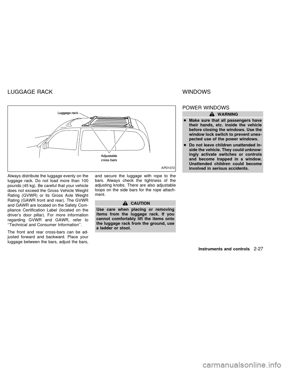
Always distribute the luggage evenly on the
luggage rack. Do not load more than 100
pounds (45 kg). Be careful that your vehicle
does not exceed the Gross Vehicle Weight
Rating (GVWR) or its Gross Axle Weight
Rating (GAWR front and rear). The GVWR
and GAWR are located on the Safety Com-
pliance Certification Label (located on the
driver's door pillar). For more information
regarding GVWR and GAWR, refer to
``Technical and Consumer Information''.
The front and rear cross-bars can be ad-
justed forward and backward. Place your
luggage between the bars, adjust the bars,and secure the luggage with rope to the
bars. Always check the tightness of the
adjusting knobs. There are also adjustable
loops on the side bars for the rope attach-
ment.
CAUTION
Use care when placing or removing
items from the luggage rack. If you
cannot comfortably lift the items onto
the luggage rack from the ground, use
a ladder or stool.
POWER WINDOWS
WARNING
cMake sure that all passengers have
their hands, etc. inside the vehicle
before closing the windows. Use the
window lock switch to prevent unex-
pected use of the power windows.
c
Do not leave children unattended in-
side the vehicle. They could unknow-
ingly activate switches or controls
and become trapped in a window.
Unattended children could become
involved in serious accidents.
APD1072
LUGGAGE RACK WINDOWS
Instruments and controls2-27
ZX
Page 115 of 292

The main switch (on the driver side) opens
or closes the driver's, and passenger's win-
dows, and (if so equipped) rear vent win-
dows.
To open the window, press the switch down.
To close the window, lift the switch up.
The power windows operate when the igni-
tion key is in the ON position, or for 15
minutes after the ignition key is turned to the
OFF position. If the driver's or passenger's
door is opened during this 15 minute period,
power to the windows is cancelled.
Locking passenger's window
When the power window lock-out button is
pushed in, the passenger's window cannot
be opened or closed. Push the power win-
dow lock-out button again to cancel this
feature.
Automatic operation
To fully open the driver side window, press
down firmly on the switch and release it; you
do not need to hold the switch down. The
window automatically opens all the way.
The automatic feature can be interrupted
before the window is fully open by briefly
lifting up on the switch as the window moves
down.
AIC1079AIC1080
2-28Instruments and controls
ZX
Page 116 of 292

The passenger side switch opens or closes
the passenger window only. To open the
window, press the switch down. To close
the window, lift the switch up.Use the vent window switches on the driv-
er's side window controls to open and close
the power vent windows. To open one of the
power vent windows, press the switch
down. To close the window, lift the switch
up.
The power vent windows operate when the
ignition key is in the ON position, or for 15
minutes after the ignition key is turned to the
OFF position. If the driver's or passenger's
door is opened during this 15 minute period,
power to the vent windows is cancelled.To open the manual vent windows, pull the
rear portion of the latch toward you until it
releases. To lock the window in the open
position, push the latch rearward until you
hear it latch. To close the windows, pull the
latch toward you and push the rear portion
of the latch toward the rear of the vehicle
until you feel it latch.
AIC1081AIC1067AIC0111
POWER VENT WINDOWS
(if so equipped)MANUAL VENT WINDOWS
Instruments and controls2-29
ZX
Page 117 of 292
The sunroof operates when the ignition key
is in the ON position, or for 15 minutes after
the ignition key is turned to the OFF posi-
tion. If the driver's or passenger's door is
opened during this 15 minute period, power
to the sunroof is cancelled.
NOTE:
If the battery is discharged or is discon-
nected, the sunroof may not operate cor-
rectly, and must be reset.
To reset a fully or partially open sunroof:
1. Push and hold the UP/CLOSE side of the
sunroof switch until the sunroof closes,and tilts up to the fully open position, then
release the switch.
2. Push and hold the DOWN/OPEN side of
the switch until the sunroof lowers com-
pletely. The sunroof is now reset and
should operate correctly.
To reset a fully or partially tilted, or closed
sunroof:
1. Push and hold the UP/CLOSE side of the
sunroof switch until the sunroof stops
tilting up, then release the switch.
2. Push and hold the DOWN/OPEN side of
the switch until the sunroof lowers com-
pletely. The sunroof is now reset and
should operate correctly.
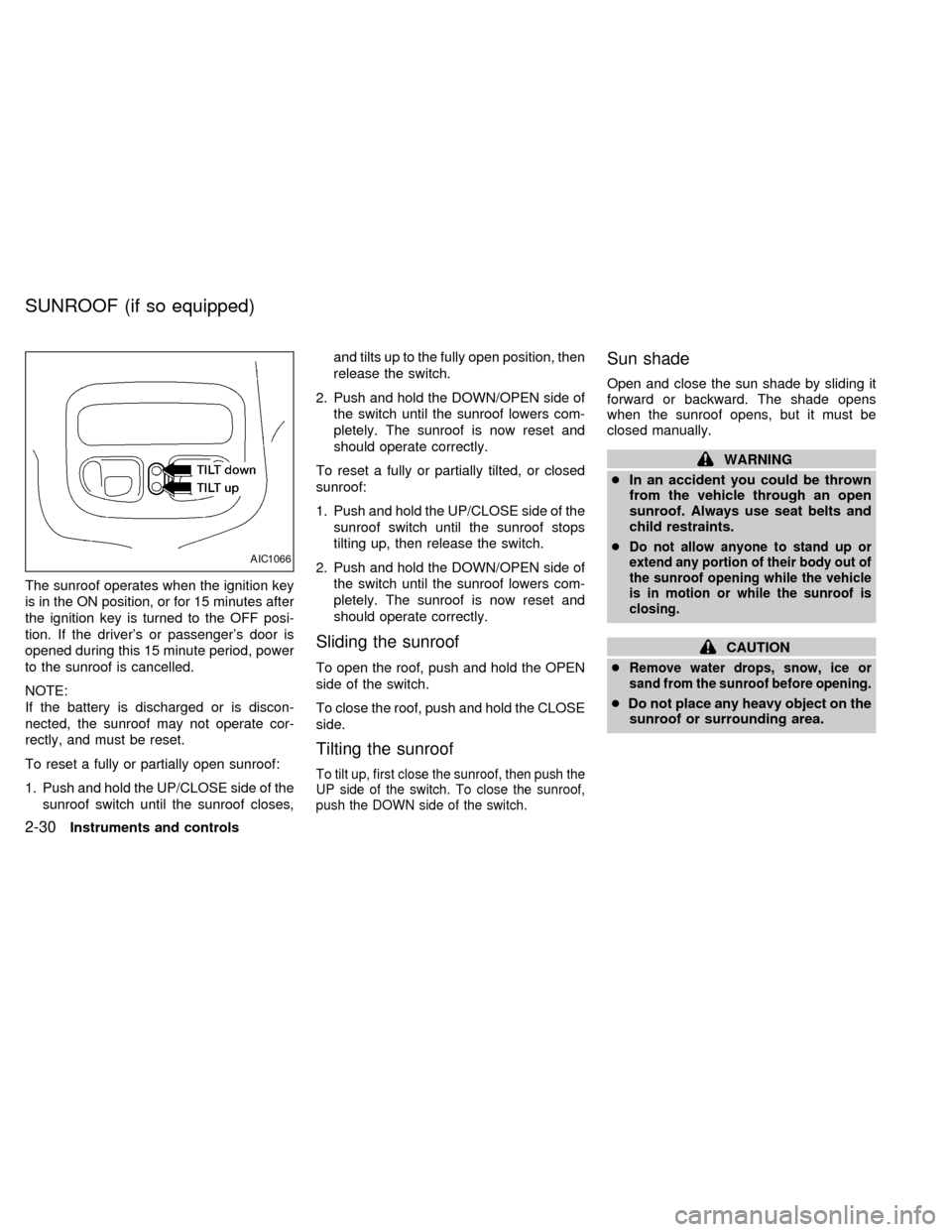
Sliding the sunroof
To open the roof, push and hold the OPEN
side of the switch.
To close the roof, push and hold the CLOSE
side.
Tilting the sunroof
To tilt up, first close the sunroof, then push the
UP side of the switch. To close the sunroof,
push the DOWN side of the switch.
Sun shade
Open and close the sun shade by sliding it
forward or backward. The shade opens
when the sunroof opens, but it must be
closed manually.
WARNING
cIn an accident you could be thrown
from the vehicle through an open
sunroof. Always use seat belts and
child restraints.
c
Do not allow anyone to stand up or
extend any portion of their body out of
the sunroof opening while the vehicle
is in motion or while the sunroof is
closing.
CAUTION
c
Remove water drops, snow, ice or
sand from the sunroof before opening.
cDo not place any heavy object on the
sunroof or surrounding area.
AIC1066
SUNROOF (if so equipped)
2-30Instruments and controls
ZX
Page 118 of 292
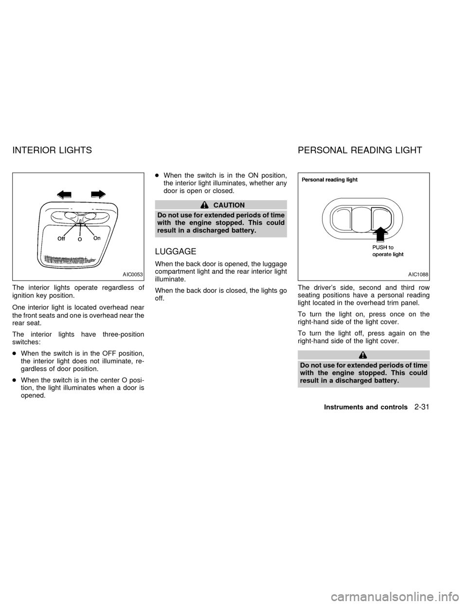
The interior lights operate regardless of
ignition key position.
One interior light is located overhead near
the front seats and one is overhead near the
rear seat.
The interior lights have three-position
switches:
cWhen the switch is in the OFF position,
the interior light does not illuminate, re-
gardless of door position.
cWhen the switch is in the center O posi-
tion, the light illuminates when a door is
opened.cWhen the switch is in the ON position,
the interior light illuminates, whether any
door is open or closed.
CAUTION
Do not use for extended periods of time
with the engine stopped. This could
result in a discharged battery.
LUGGAGE
When the back door is opened, the luggage
compartment light and the rear interior light
illuminate.
When the back door is closed, the lights go
off.The driver's side, second and third row
seating positions have a personal reading
light located in the overhead trim panel.
To turn the light on, press once on the
right-hand side of the light cover.
To turn the light off, press again on the
right-hand side of the light cover.
Do not use for extended periods of time
with the engine stopped. This could
result in a discharged battery.
AIC0053AIC1088
INTERIOR LIGHTS PERSONAL READING LIGHT
Instruments and controls2-31
ZX
Page 119 of 292
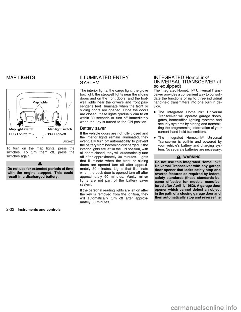
To turn on the map lights, press the
switches. To turn them off, press the
switches again.
Do not use for extended periods of time
with the engine stopped. This could
result in a discharged battery.The interior lights, the cargo light, the glove
box light, the stepwell lights near the sliding
doors and on the front doors, and the foot-
well lights near the driver's and front pas-
senger's feet illuminate when the front or
sliding doors are opened. Once the doors
are closed, these lights gradually dim to off
within 30 seconds or turn off immediately
when the key is turned to the ON position.
Battery saver
If the vehicle doors are not fully closed and
the interior lights remain illuminated, they
eventually turn off automatically to prevent
the battery from becoming discharged. If the
interior lights are left in the ON position, with
all doors closed, they will automatically turn
off after approximately 30 minutes. Lights
that illuminate when the front or sliding
doors are opened turn off after approxi-
mately 30 minutes. Lights that illuminate
when the back door is opened turn off after
approximately 60 minutes. Vanity mirror
lights are not part of the battery saver
system.
If the personal reading lights are left on after
the key is removed from the ignition, they
will automatically turn off after approxi-
mately 30 minutes.The Integrated HomeLinkTUniversal Trans-
ceiver provides a convenient way to consoli-
date the functions of up to three individual
hand-held transmitters into one built-in de-
vice.
cThe Integrated HomeLinkTUniversal
Transceiver will operate garage doors,
gates, home/office lighting systems and
security systems by storing and transmit-
ting the programming information of your
current hand-held transmitters.
c
The Integrated HomeLinkTUniversal
Transceiver is built-in and powered by
your vehicle's battery and charging sys-
tem. No separate batteries are necessary.
WARNING
Do not use this Integrated HomeLinkT
Universal Transceiver with any garage
door opener that lacks safety stop and
reverse features as required by federal
safety standards (these standards be-
came effective for models manufac-
tured after April 1, 1982). A garage door
opener which cannot detect an object
in the path of a closing garage door and
then automatically stop and reverse the
AIC1097
MAP LIGHTS ILLUMINATED ENTRY
SYSTEMINTEGRATED HomeLinkT
UNIVERSAL TRANSCEIVER (if
so equipped)
2-32Instruments and controls
ZX
Page 120 of 292
door, does not meet current federal
safety standards. Using a garage door
opener without these features in-
creases the risk of serious injury or
death.
PROGRAMMING HomeLinkT
WARNING
During the programming procedure
your garage door or security gate will
open and close (if the transmitter is
within range). Make sure that people or
objects are clear of the garage door,
gate, etc. that you are programming.Your vehicle's engine should be turned
off while programming your transmit-
ter. The Integrated HomeLinkTUniver-
sal Transceiver may not work with
older garage door openers that do not
meet current Federal Consumer Safety
Standards.
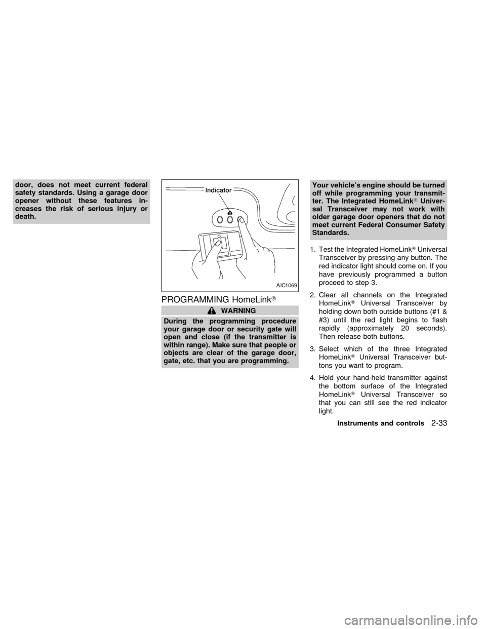
1. Test the Integrated HomeLinkTUniversal
Transceiver by pressing any button. The
red indicator light should come on. If you
have previously programmed a button
proceed to step 3.
2. Clear all channels on the Integrated
HomeLinkTUniversal Transceiver by
holding down both outside buttons (#1 &
#3) until the red light begins to flash
rapidly (approximately 20 seconds).
Then release both buttons.
3. Select which of the three Integrated
HomeLinkTUniversal Transceiver but-
tons you want to program.
4. Hold your hand-held transmitter against
the bottom surface of the Integrated
HomeLinkTUniversal Transceiver so
that you can still see the red indicator
light.
AIC1069
Instruments and controls2-33
ZX