ECO mode NISSAN ROGUE 2021 Owner´s Manual
[x] Cancel search | Manufacturer: NISSAN, Model Year: 2021, Model line: ROGUE, Model: NISSAN ROGUE 2021Pages: 556, PDF Size: 2.7 MB
Page 195 of 556
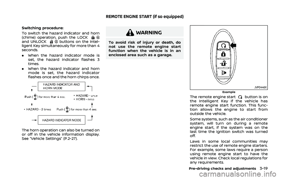
Switching procedure:
To switch the hazard indicator and horn
(chime) operation, push the LOCK
and UNLOCKbuttons on the Intel-
ligent Key simultaneously for more than 4
seconds.
. When the hazard indicator mode is
set, the hazard indicator flashes 3
times.
. When the hazard indicator and horn
mode is set, the hazard indicator
flashes once and the horn chirps once.
The horn operation can also be turned on
or off in the vehicle information display.
See “Vehicle Settings” (P.2-27).
WARNING
To avoid risk of injury or death, do
not use the remote engine start
function when the vehicle is in an
enclosed area such as a garage.
JVP0446XExample
The remote engine startbutton is on
the Intelligent Key if the vehicle has
remote engine start function. This func-
tion allows the engine to start from
outside the vehicle.
Some systems, such as the air conditioner
system, will turn on during a remote
engine start, if the system was on the
last time the ignition switch was turned
off.
Laws in some local communities may
restrict the use of remote engine starters.
For example, some laws require a person
using remote engine start to have the
vehicle in view. Check local regulations for
any requirements.
Pre-driving checks and adjustments3-19
REMOTE ENGINE START (if so equipped)
Page 201 of 556
Power open (using switches)
When the liftgate is fully closed, the
liftgate will fully open automatically by:
.pushing the power liftgate switch
on the instrument panel for more
than 1 second
. pushing the liftgate opener switch
.pushing the power liftgate buttonon the key for more than 1 second
The outside chime sounds when the
liftgate starts opening.
NOTE:
The liftgate can be opened by the
power liftgate switch
or the power
liftgate buttoneven if the
liftgate is locked. The liftgate can be
unlocked and opened independently of
the other doors, even when they are
locked. The liftgate must be unlocked
(or the Intelligent Key must be within
range) to open with the liftgate opener
switch
.
Power close (using switches)
When the liftgate is fully opened, the
liftgate will fully close automatically by:
. pushing the power liftgate switch
on the instrument panel for more
than 1 second .
pushing the power liftgate button
on the key for more than 1 second
. pushing the power liftgate close
switch
on the lower part of the
liftgate for 1 second
The outside chime sounds when the
liftgate starts closing.
Power close and lock
When the liftgate is fully opened and the
Intelligent Key is carried with you near the
liftgate, the liftgate will fully close and lock
automatically by pushing the power lift-
gate lock switch
on the lower part of
the liftgate.
The outside chime sounds when the
liftgate starts closing.
Stop and reverse function (if so
equipped)
The power liftgate will stop immediately if
one of the following actions is performed
during power open or close.
. pushing the power liftgate switch
.pushing the liftgate opener switch
.pushing the power liftgate close
switchon the lower part of the
liftgate
. pushing the power liftgate button
on the key
And then the power liftgate will move in the reverse direction if one of the above
actions is performed again.
The outside chime sounds when the
liftgate starts to reverse.
Auto reverse function
The auto-reverse function enables the
liftgate to automatically reverse when
something is caught in the liftgate as it
is opening or closing. When the control
unit detects an obstacle, the liftgate will
reverse and return to the full open or full
close position.
If a second obstacle is detected, the
liftgate motion will stop. The liftgate will
enter the manual mode.
A pinch sensor is mounted on each side
of the liftgate. If an obstacle is detected
by the pinch sensor during power close,
the liftgate will reverse and return to the
full open position immediately.
NOTE:
If the pinch sensor is damaged or
removed, the power close function will
not operate.
WARNING
There is a small distance immedi-
ately before the closed position that
cannot be detected. Make sure that
Pre-driving checks and adjustments3-25
Page 204 of 556
3-28Pre-driving checks and adjustments
CAUTION
Do not set the height of the liftgate
below approximately 1/3 of the way
to the floor using garage mode. Even
if you set the height below approxi-
mately 1/3 of the way to the floor,
the height will automatically be set
to approximately 1/3 of the way to
the floor.
AUTO CLOSURE (if so equipped)
When the liftgate reaches the secondary
position, the closure motor engages and
pulls the liftgate to its primary latch
position.
Do not apply excessive force when the
auto closure is operating. Excessive
force applied may cause the mechan-
ism to malfunction.
CAUTION
.The liftgate will automatically
close from the secondary posi-
tion. To avoid pinching, keep
hands and fingers away from
liftgate opening. .
Do not let children operate the
liftgate.
WAD0155X
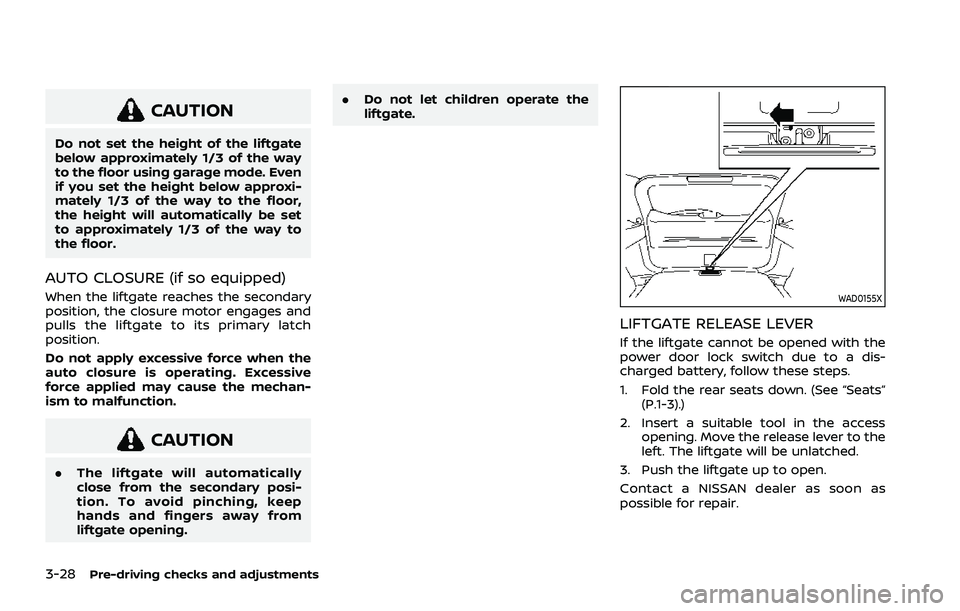
LIFTGATE RELEASE LEVER
If the liftgate cannot be opened with the
power door lock switch due to a dis-
charged battery, follow these steps.
1. Fold the rear seats down. (See “Seats”
(P.1-3).)
2. Insert a suitable tool in the access opening. Move the release lever to the
left. The liftgate will be unlatched.
3. Push the liftgate up to open.
Contact a NISSAN dealer as soon as
possible for repair.
Page 213 of 556
3. The indicator light for the pushedmemory switch will come on and stay
on for approximately 5 seconds.
4. The chime will sound if the memory has been stored.
NOTE:
If a new memory position is stored in
the same memory switch, the previous
memory position will be overwritten by
the new stored position.
Confirming memory storage
Push the SET switch. If a memory position
has not been stored in the switch (1 or 2)
the indicator light for the respective
switch will come ON for approximately
0.5 seconds. If a memory position has
been stored in the switch (1 or 2) then the
indicator light for the respective switch
will stay ON for approximately 5 seconds.
Recalling switch memory positions
To recall the manually stored positions,
push the memory switch (1 or 2). The
driver’s seat and the outside mirrors will
move to the positions stored in the
memory switch.
Linking log-in function to a stored
memory position (models with na-
vigation system)
The log-in function can be linked to a
stored memory position with the follow-
ing procedure.
1. Place the ignition switch in the ON position while carrying the Intelligent
Key that was registered to the vehicle
with a log-in function.
NOTE:
Make sure the Intelligent Key is far
apart. Otherwise, the vehicle may
detect the wrong Intelligent Key.
2. Adjust the position of the driver’s seat and outside mirrors. (See “Seats” (P.1-3)
and “Outside mirrors” (P.3-34).)
3. Place the ignition switch in the OFF position.
The next time you log in (selecting the
user on the display) after placing the
ignition switch in the ON position while
carrying the Intelligent Key, the system
will automatically adjust to the memor-
ized driving position. (See the separate
NissanConnect® Owner’s Manual.)
Linking an Intelligent Key to a
stored memory position (models
without navigation system)
Each Intelligent Key can be linked to a
stored memory position (memory switch
1 or 2) with the following procedure.
1. Follow steps 1-3 in the “Memory sto- rage function” (P.3-36) for storing the
memory position.
2. The indicator light for the pushed memory switch will come on. While
the indicator light is on for 5 seconds,
press the
button and thebutton on the Intelligent Key in suc-
cession. The indicator light of the
linked memory switch will blink. After
the indicator light goes off, the Intel-
ligent Key is linked to that memory
setting.
Once it is linked, when ignition switch is
placed in the OFF position, pressing the
button on the Intelligent Key will
move the driver’s seat and outside mir-
rors to the linked memory switch posi-
tion.
NOTE:
If a new memory position is stored in
the linked memory switch, then the
Intelligent Key will link the new position
and overwrites the previous position.
Pre-driving checks and adjustments3-37
Page 216 of 556
4-2Monitor, heater, air conditioner, audio and phone systems
For models with NissanConnect® System,
refer to NissanConnect® Owner’s Manual
that includes the following information.
Available functions may vary depending
on the models and specifications.
.Audio
. Hands-Free Phone
. Apple CarPlay®
. Android Auto
TM
.NissanConnect® Services powered by
SiriusXM®
. Navigation system
. Voice recognition
. Information and settings viewable on
NissanConnect®
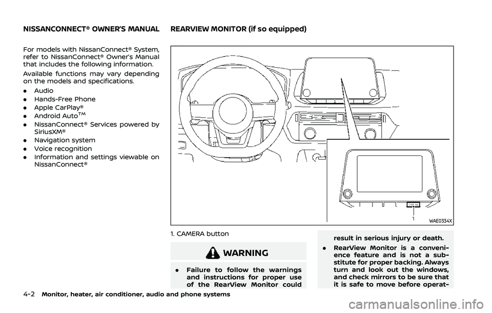
WAE0334X
1. CAMERA button
WARNING
.Failure to follow the warnings
and instructions for proper use
of the RearView Monitor could result in serious injury or death.
. RearView Monitor is a conveni-
ence feature and is not a sub-
stitute for proper backing. Always
turn and look out the windows,
and check mirrors to be sure that
it is safe to move before operat-
NISSANCONNECT® OWNER’S MANUALREARVIEW MONITOR (if so equipped)
Page 241 of 556
WARNING
.The heater and air conditioner
operate only when the engine is
running.
. Never leave children or adults
who would normally require the
support of others alone in the
vehicle. Pets should not be left
alone either. They could unknow-
ingly activate switches or con-
trols and inadvertently become
involved in a serious accident
and injure themselves. On hot,
sunny days, temperatures in a
closed vehicle could quickly be-
come high enough to cause se-
vere or possibly fatal injuries to
people or animals.
. Do not use the recirculation mode
for long periods as it may cause
the interior air to become stale
and the windows to fog up.
. Do not adjust the heating and air
conditioning controls while driv-
ing so that full attention may be
given to vehicle operation.
The heater and air conditioner operate
when the engine is running. The air blower will operate even if the engine is
turned off and the ignition switch is
placed in the ON position.
NOTE:
.
Odors from inside and outside the
vehicle can build up in the air condi-
tioner unit. Odor can enter the pas-
senger compartment through the
ventilators.
. When parking, set the heater and air
conditioner controls to turn off air
recirculation to allow fresh air into
the passenger compartment. This
should help reduce odors inside the
vehicle.
Monitor, heater, air conditioner, audio and phone systems4-27
HEATER AND AIR CONDITIONER
Page 245 of 556
air conditioner automatically turns on if
the outside temperature is more than
slightly above freezing. This dehumidifies
the air which helps defog the windshield.
The air recirculation mode automatically
turns off, allowing outside air to be drawn
into the passenger compartment to
further improve the defogging perfor-
mance.
The air conditioner is always turned on in
the
ormode, regardless of
whether the indicator light is on or off.
NOTE:
. The air conditioner system should
be operated for approximately 10
minutes at least once a month. This
helps prevent damage to the air
conditioner system due to the lack
of lubrication.
. A visible mist may be seen coming
from the ventilators in hot, humid
conditions as the air is cooled ra-
pidly. This does not indicate a mal-
function.
. If the engine coolant temperature
becomes too high, the air recircula-
tion mode will be activated and the
indicator light will turn on automa-
tically.
. If the engine coolant temperature
gauge indicates engine coolant tem-
perature over the normal range, turn the air conditioner off. (See “If your
vehicle overheats” (P.6-13).)
Monitor, heater, air conditioner, audio and phone systems4-31
Page 247 of 556
2. Turn the temperature control dial onthe corresponding side to set the
desired temperature.
.You can individually set tempera-tures for the driver’s side and front
passenger’s side when the indica-
tor light on the SYNC button is not
illuminated.
A visible mist may be seen coming from
the ventilators in hot, humid conditions as
the air is cooled rapidly. This does not
indicate a malfunction.
Heating (A/C OFF):
The air conditioner does not activate in
this mode. Use this mode when you only
need to heat.
1. Push the AUTO button on. (The in- dicator light on the button will illumi-
nate.)
2. Push the A/C button. (The indicator light will turn off.)
3. Turn the temperature control dial on the corresponding side to set the
desired temperature.
.You can individually set tempera-
tures for the driver’s side and front
passenger’s side when the indica-
tor light on the SYNC button is not
illuminated.
.The temperature of the passengercompartment will be maintained
automatically. Air flow distribution
and fan speed are also controlled
automatically.
NOTE:
. Do not set the temperature lower
than the outside air temperature or
the system may not work properly.
. Not recommended if windows fog
up.
Dehumidified defrosting or defogging:
1. Push the
button. (The indicator
light on the button will turn on.)
2. Turn the temperature control dial on the corresponding side to set the
desired temperature.
.To quickly remove ice from theoutside of the windows, use the
button to set the fan speed to
maximum.
.As soon as possible after the wind- shield is clean, push the AUTO
button to return to the automatic
mode.
.When thebutton is pushed, the
air conditioner will automatically be
turned on at outside temperatures
more than slightly above freezing.
The air recirculation mode auto-
matically turns off, allowing outside air to be drawn into the passenger
compartment to further improve
the defogging performance.
Manual operation
Fan speed control:
Push the
buttons to manually control
the fan speed.
Air intake control:
The air intake control mode will change
each time the
button is pushed.
. When the indicator light is turned on,
the air recirculates inside the vehicle.
. When the indicator light is turned off,
the air flow is drawn from outside the
vehicle.
. To switch to automatic control mode,
push and hold the
button for
about 2 seconds. The indicator light
will blink, and then the air intake will
be controlled automatically.
Air flow control:
Pushing the
button manually con-
trols air flow and selects the air outlet:
Monitor, heater, air conditioner, audio and phone systems4-33
Page 250 of 556
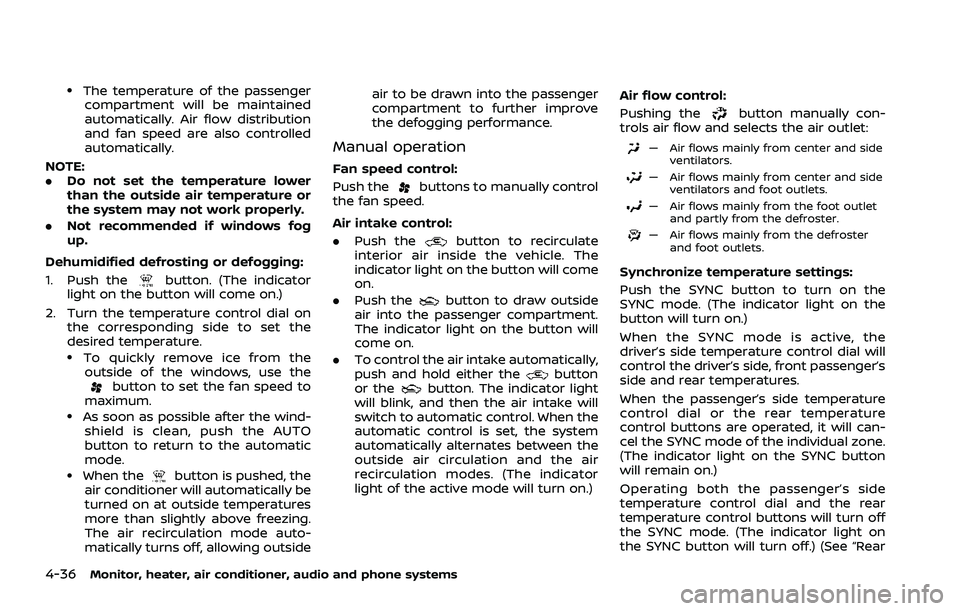
4-36Monitor, heater, air conditioner, audio and phone systems
.The temperature of the passengercompartment will be maintained
automatically. Air flow distribution
and fan speed are also controlled
automatically.
NOTE:
. Do not set the temperature lower
than the outside air temperature or
the system may not work properly.
. Not recommended if windows fog
up.
Dehumidified defrosting or defogging:
1. Push the
button. (The indicator
light on the button will come on.)
2. Turn the temperature control dial on the corresponding side to set the
desired temperature.
.To quickly remove ice from theoutside of the windows, use the
button to set the fan speed to
maximum.
.As soon as possible after the wind- shield is clean, push the AUTO
button to return to the automatic
mode.
.When thebutton is pushed, the
air conditioner will automatically be
turned on at outside temperatures
more than slightly above freezing.
The air recirculation mode auto-
matically turns off, allowing outside air to be drawn into the passenger
compartment to further improve
the defogging performance.
Manual operation
Fan speed control:
Push the
buttons to manually control
the fan speed.
Air intake control:
. Push the
button to recirculate
interior air inside the vehicle. The
indicator light on the button will come
on.
. Push the
button to draw outside
air into the passenger compartment.
The indicator light on the button will
come on.
. To control the air intake automatically,
push and hold either the
button
or thebutton. The indicator light
will blink, and then the air intake will
switch to automatic control. When the
automatic control is set, the system
automatically alternates between the
outside air circulation and the air
recirculation modes. (The indicator
light of the active mode will turn on.) Air flow control:
Pushing the
button manually con-
trols air flow and selects the air outlet:
— Air flows mainly from center and side
ventilators.
— Air flows mainly from center and sideventilators and foot outlets.
— Air flows mainly from the foot outletand partly from the defroster.
— Air flows mainly from the defrosterand foot outlets.
Synchronize temperature settings:
Push the SYNC button to turn on the
SYNC mode. (The indicator light on the
button will turn on.)
When the SYNC mode is active, the
driver’s side temperature control dial will
control the driver’s side, front passenger’s
side and rear temperatures.
When the passenger’s side temperature
control dial or the rear temperature
control buttons are operated, it will can-
cel the SYNC mode of the individual zone.
(The indicator light on the SYNC button
will remain on.)
Operating both the passenger’s side
temperature control dial and the rear
temperature control buttons will turn off
the SYNC mode. (The indicator light on
the SYNC button will turn off.) (See “Rear
Page 252 of 556
4-38Monitor, heater, air conditioner, audio and phone systems
OPERATING TIPS (for automatic air
conditioner)
When the engine coolant temperature
and outside air temperature are low, the
air flow from the foot outlets may be
limited when in the automatic mode.
However, this is not a malfunction. After
the coolant temperature warms up, air
flow from the foot outlets will operate
normally.
For rear temperature control (if so
equipped):
.The purpose of the rear temperature
control is to vary the temperature of
the rear airflow.
. The amount of airflow to the rear
ventilators is primarily controlled by
the front passenger’s blower and
mode settings.
. The amount of airflow to the rear
ventilators is also affected by the rear
temperature setting. Higher rear tem-
perature settings have lower airflow
amounts than cooler temperature
settings. This condition ensures better
comfort to the head and face area,
while primary heating for the rear
passenger seats is provided through
the foot outlets.
WAE0350X
WAE0351X
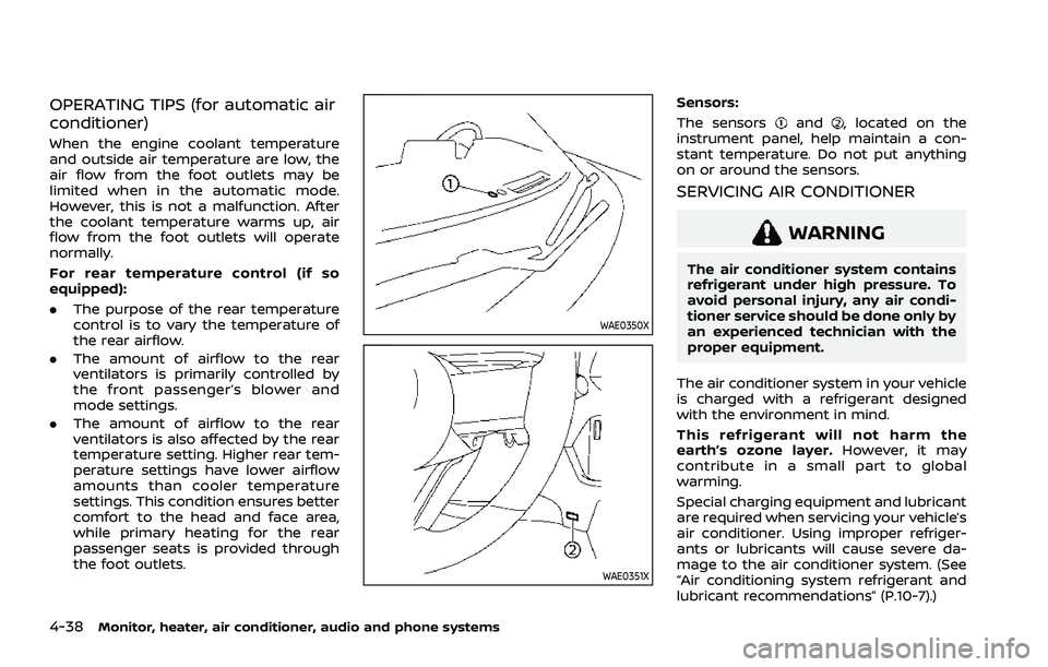
Sensors:
The sensors
and, located on the
instrument panel, help maintain a con-
stant temperature. Do not put anything
on or around the sensors.
SERVICING AIR CONDITIONER
WARNING
The air conditioner system contains
refrigerant under high pressure. To
avoid personal injury, any air condi-
tioner service should be done only by
an experienced technician with the
proper equipment.
The air conditioner system in your vehicle
is charged with a refrigerant designed
with the environment in mind.
This refrigerant will not harm the
earth’s ozone layer. However, it may
contribute in a small part to global
warming.
Special charging equipment and lubricant
are required when servicing your vehicle’s
air conditioner. Using improper refriger-
ants or lubricants will cause severe da-
mage to the air conditioner system. (See
“Air conditioning system refrigerant and
lubricant recommendations” (P.10-7).)