stop start NISSAN SENTRA 2020 Owner´s Manual
[x] Cancel search | Manufacturer: NISSAN, Model Year: 2020, Model line: SENTRA, Model: NISSAN SENTRA 2020Pages: 528, PDF Size: 3.56 MB
Page 304 of 528
P (Park)
CAUTION
To prevent transmission damage, use
the P (Park) position only when the ve-
hicle is completely stopped.
Use the P (Park) shif t lever position when
the vehicle is parked or when starting the
engine. Make sure the vehicle is completely
stopped. The brake pedal must be de-
pressed and the shif t lever button
pressed in to move the shif t lever from N
(Neutral) or any drive position to P (Park).
Apply the parking brake. When parking on a
hill, apply the parking brake first, then place
the shif t lever into the P (Park) position.
R (Reverse)
CAUTION
To prevent transmission damage, use
the R (Reverse) position only when the
vehicle is completely stopped.
Use the R (Reverse) position to back up.
Make sure the vehicle is completely
stopped before selecting the R (Reverse)
position. The brake pedal must be de-
pressed and the shif t lever button pressed in to move the shif t lever from P
(Park), N (Neutral) or any drive position to
R (Reverse).
N (Neutral)
Neither forward nor reverse gear is en-
gaged. The engine can be started in this
position. You may shif t to N (Neutral) and
restart a stalled engine while the vehicle is
moving.
D (Drive)
Use this position for all normal forward
driving.
L (Low) (if so equipped)
Use this position for maximum engine
braking on steep downhill gradients/
climbing steep slopes and whenever ap-
proaching sharp bends. Do not use the L
(Low) position in any other circumstances.
Manual shif t mode (if so
equipped)
When the shif t lever is in the manual shif t
gate, the transmission is ready for the
manual shif t mode. Shif t ranges can be
selected manually by moving the shif t le-
ver up or down. To cancel manual shif t
mode, return the shif t lever to the D (Drive)position. The transmission returns to auto-
matic driving mode.
When the shif t lever is shif ted from D (Drive)
to the manual shif t gate with the vehicle
stopped or while driving, the transmission
enters the manual shif t mode. Shif t ranges
can be selected manually. In the manual
shif t mode, the shif t range is displayed on
the position indicator in the meter. When
moving the shif t lever to the manual shif t
gate, the position indicator displays 1 (1st)
up to 7 (7th) depending on vehicle speed.
Shif t ranges up or down one by one as
follows:
1⇔
2⇔ 3⇔ 4⇔ 5⇔ 6⇔ 7
M7 (7th)
Use this position for all normal forward
driving at highway speeds.
M6 (6th) and M5 (5th)
Use this position when driving up long
slopes or for engine braking when driving
down long slopes.
M4 (4th), M3 (3rd) and M2 (2nd)
Use for hill climbing or engine braking on
downhill grades.
5-18Starting and driving
Page 305 of 528
M1 (1st)
Use this position when climbing steep hills
slowly or driving slowly through deep snow,
sand or mud, or for maximum engine brak-
ing on steep downhill grades.
• Remember not to drive at high speeds forextended periods of time in lower than
the 6th range. This reduces fuel economy.
When shif ting up
Move the shif t lever to the + (up) side. (Shif ts
to higher range.)
When shif ting down
Move the shif t lever to the − (down) side.
(Shif ts to lower range.)
• Moving the shif t lever rapidly to the same side twice will shif t the ranges in succes-
sion.
• The transmission will automatically downshif t the gears. (For example, if you
select the 3rd range, the transmission will
shif t down between the 3rd and 1st
gears.)
When canceling the manual shif t mode
Return the shif t lever to the D (Drive) posi-
tion to return the transmission to the nor-
mal driving mode. •
In the manual shif t mode, the trans-
mission may not shif t to the selected
gear. This helps maintain driving per-
formance and reduces the chance of
vehicle damage or loss of control.
• When this situation occurs, the Con-
tinuously Variable Transmission (CVT)
position indicator light will blink and
the chime will sound.
• In the manual shif t mode, the trans-
mission may shif t up automatically to a
higher range than selected if the en-
gine speed is too high. When the ve-
hicle speed decreases, the transmis-
sion automatically shif ts down and
shif ts to 1st gear before the vehicle
comes to a stop.
• CVT operation is limited to automatic drive mode when CVT fluid temperature
is extremely low even if manual shif t
mode is selected. This is not a malfunc-
tion. When CVT fluid warms up, manual
mode can be selected.
• When the CVT fluid temperature is high, the shif t range may upshif t in lower rpm
than usual. This is not a malfunction.
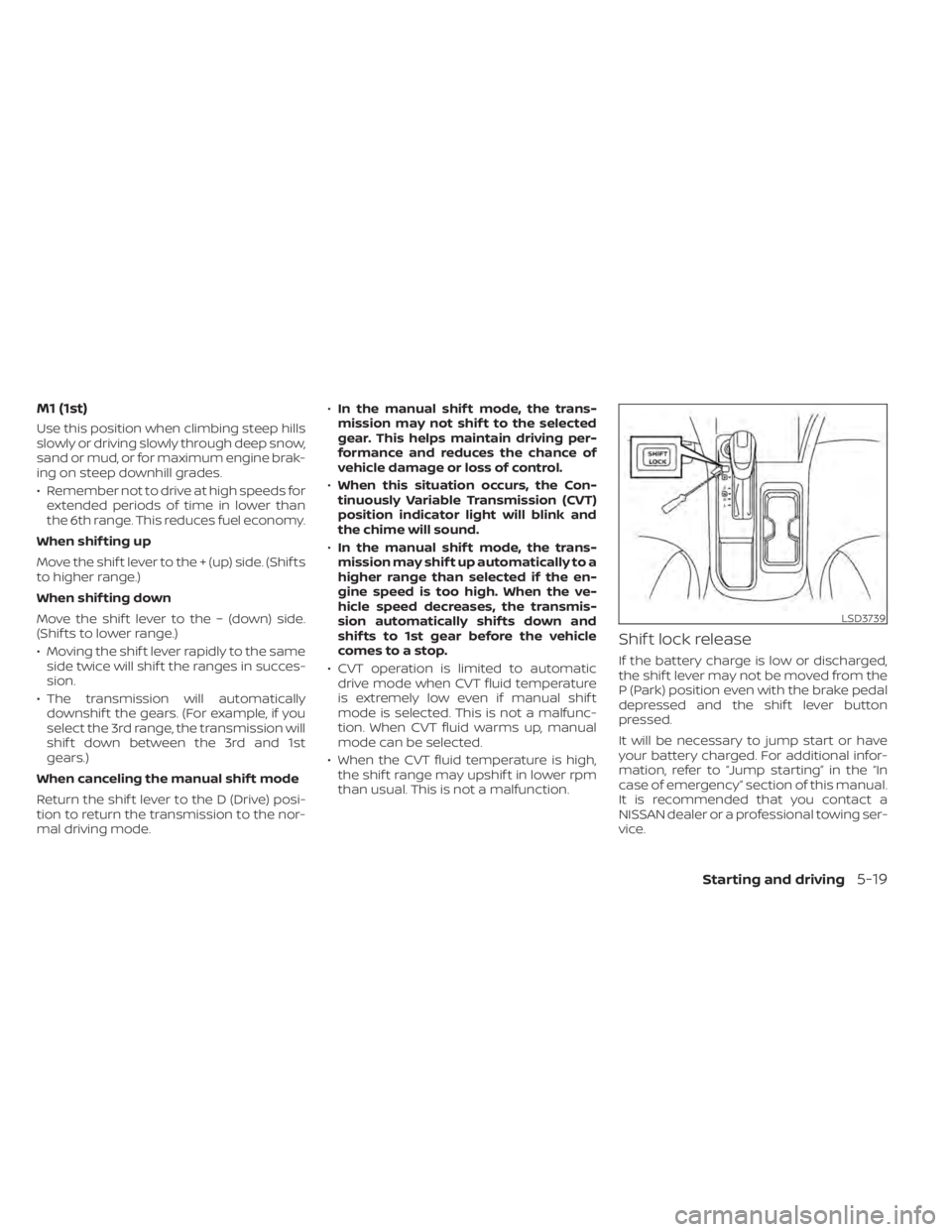
Shif t lock release
If the battery charge is low or discharged,
the shif t lever may not be moved from the
P (Park) position even with the brake pedal
depressed and the shif t lever button
pressed.
It will be necessary to jump start or have
your battery charged. For additional infor-
mation, refer to “Jump starting” in the “In
case of emergency” section of this manual.
It is recommended that you contact a
NISSAN dealer or a professional towing ser-
vice.
LSD3739
Starting and driving5-19
Page 306 of 528
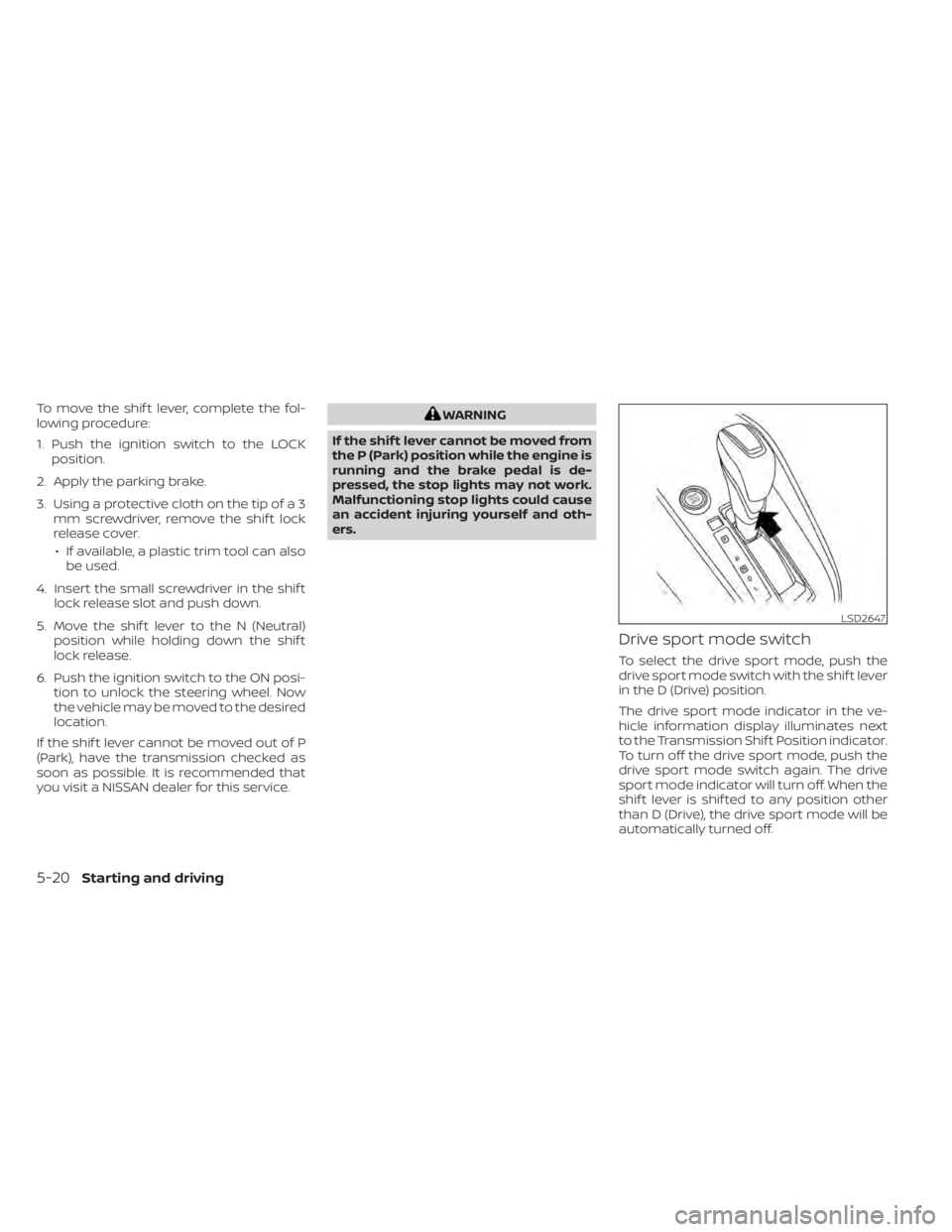
To move the shif t lever, complete the fol-
lowing procedure:
1. Push the ignition switch to the LOCKposition.
2. Apply the parking brake.
3. Using a protective cloth on the tip of a 3 mm screwdriver, remove the shif t lock
release cover.
• If available, a plastic trim tool can also be used.
4. Insert the small screwdriver in the shif t lock release slot and push down.
5. Move the shif t lever to the N (Neutral) position while holding down the shif t
lock release.
6. Push the ignition switch to the ON posi- tion to unlock the steering wheel. Now
the vehicle may be moved to the desired
location.
If the shif t lever cannot be moved out of P
(Park), have the transmission checked as
soon as possible. It is recommended that
you visit a NISSAN dealer for this service.WARNING
If the shif t lever cannot be moved from
the P (Park) position while the engine is
running and the brake pedal is de-
pressed, the stop lights may not work.
Malfunctioning stop lights could cause
an accident injuring yourself and oth-
ers.
Drive sport mode switch
To select the drive sport mode, push the
drive sport mode switch with the shif t lever
in the D (Drive) position.
The drive sport mode indicator in the ve-
hicle information display illuminates next
to the Transmission Shif t Position indicator.
To turn off the drive sport mode, push the
drive sport mode switch again. The drive
sport mode indicator will turn off. When the
shif t lever is shif ted to any position other
than D (Drive), the drive sport mode will be
automatically turned off.
LSD2647
5-20Starting and driving
Page 307 of 528
OFF position:
For normal driving and fuel economy, use
the OFF position.
ON position:
For driving up or down long slopes where
engine braking is necessary, or for powerful
acceleration, use the ON position. The
transmission will automatically select a dif-
ferent gear ratio, allowing the engine to
provide high output.
Remember not to drive at high speeds for
extended periods of time with the drive
sport mode in the ON position. This re-
duces fuel economy.
Accelerator downshif t
— in D (Drive) position —
For passing or hill climbing, depress the
accelerator pedal to the floor. This shif ts
the transmission down into a lower gear,
depending on the vehicle speed.
Fail-safe
If the vehicle is driven under extreme
conditions, such as excessive wheel
spinning and subsequent hard braking,
the fail-safe system may be activated.
The Malfunction Indicator Light (MIL)may come on to indicate the fail-safe
mode is activated. For additional infor-
mation, refer to “Malfunction Indicator
Light (MIL)” in the “Instruments and con-
trols” section of this manual. This will oc-
cur even if all electrical circuits are func-
tioning properly. In this case, place the
ignition switch in the OFF position and
wait for 10 seconds. Then push the
switch back to the ON position. The ve-
hicle should return to its normal operat-
ing condition. If it does not return to its
normal operating condition, have the
transmission checked and repaired, if
necessary. It is recommended that you
visit a NISSAN dealer for this service.
WARNING
When the high fluid temperature pro-
tection mode or fail-safe operation oc-
curs, vehicle speed may be gradually
reduced. The reduced speed may be
lower than other traffic, which could in-
crease the chance of a collision. Be es-
pecially careful when driving. If neces-
sary, pull to the side of the road at a safe
place and allow the transmission to re-
turn to normal operation, or have it re-
paired if necessary.
MANUAL TRANSMISSION (if so
equipped)
WARNING
• Do not downshif t abruptly on slip-
pery roads. This may cause a loss of
control.
• Do not over-rev the engine when
shif ting to a lower gear. This may
cause a loss of control or engine
damage.
• Do not shif t to the N (Neutral) posi-
tion while driving. Doing so may re-
sult in an accident due to loss of en-
gine braking.
CAUTION
• Do not rest your foot on the clutch
pedal while driving. This may cause
clutch damage.
• Fully depress the clutch pedal before
shif ting to help prevent transmission
damage.
• Stop your vehicle completely before
shif ting into R (Reverse).
Starting and driving5-21
Page 308 of 528
•When the vehicle is stopped with the
engine running (for example, at a
stop light), shif t to N (Neutral) and re-
lease the clutch pedal with the foot
brake applied.
• Do not shif t to the N (Neutral) posi-
tion while driving. Doing so may re-
sult in an accident due to loss of en-
gine braking.
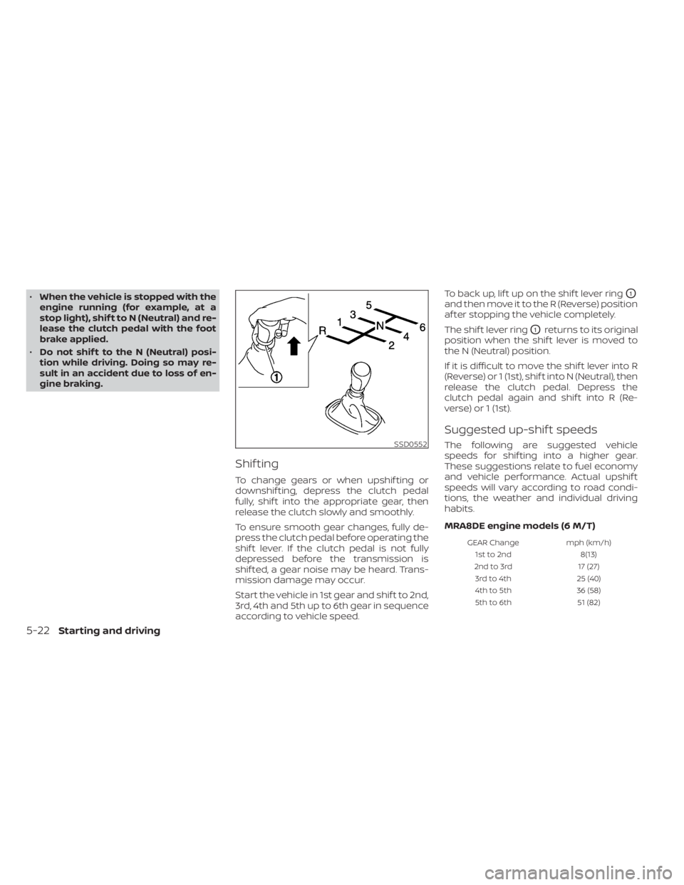
Shif ting
To change gears or when upshif ting or
downshif ting, depress the clutch pedal
fully, shif t into the appropriate gear, then
release the clutch slowly and smoothly.
To ensure smooth gear changes, fully de-
press the clutch pedal before operating the
shif t lever. If the clutch pedal is not fully
depressed before the transmission is
shif ted, a gear noise may be heard. Trans-
mission damage may occur.
Start the vehicle in 1st gear and shif t to 2nd,
3rd, 4th and 5th up to 6th gear in sequence
according to vehicle speed. To back up, lif t up on the shif t lever ring
O1
and then move it to the R (Reverse) position
af ter stopping the vehicle completely.
The shif t lever ring
O1returns to its original
position when the shif t lever is moved to
the N (Neutral) position.
If it is difficult to move the shif t lever into R
(Reverse) or 1 (1st), shif t into N (Neutral), then
release the clutch pedal. Depress the
clutch pedal again and shif t into R (Re-
verse) or 1 (1st).
Suggested up-shif t speeds
The following are suggested vehicle
speeds for shif ting into a higher gear.
These suggestions relate to fuel economy
and vehicle performance. Actual upshif t
speeds will vary according to road condi-
tions, the weather and individual driving
habits.
MRA8DE engine models (6 M/T)
GEAR Change mph (km/h)
1st to 2nd 8(13)
2nd to 3rd 17 (27)
3rd to 4th 25 (40)
4th to 5th 36 (58)
5th to 6th 51 (82)
SSD0552
5-22Starting and driving
Page 315 of 528
Action to take:
When the interior temperature is reduced,
the TSR system will resume operating au-
tomatically.
SYSTEM MALFUNCTION
If the TSR system malfunctions, it will be
turned off automatically and the system
“Malfunction” warning message will appear
in the vehicle information display.
Action to take:
If the TSR “Malfunction” message appears,
pull of the road at a safe location and stop
the vehicle. Turn the engine off and restart
the engine. If the TSR “Malfunction” mes-
sage continues to appear, have the system
checked. It is recommended that you visit a
NISSAN dealer for this service.
SYSTEM MAINTENANCE
The TSR system uses the same multi-
sensing front camera unit that is used by
the Lane Departure Warning (LDW) system,
located in front of the interior rearview mir-
ror. For additional information, refer to ”Sys-
tem maintenance” in the “Lane Departure
Warning (LDW)” section.
WARNING
Failure to follow the warnings and in-
structions for proper use of the LDW
system could result in serious injury or
death.
• This system is only a warning device
to inform the driver of a potential un-
intended lane departure. It will not
steer the vehicle or prevent loss of
control. It is the driver’s responsibility
to stay alert, drive safely, keep the
vehicle in the traveling lane, and be in
control of the vehicle at all times. The LDW system will operate when the ve-
hicle is driven at speeds of approximately
37 mph (60 km/h) and above, and only
when the lane markings are clearly visible
on the road.
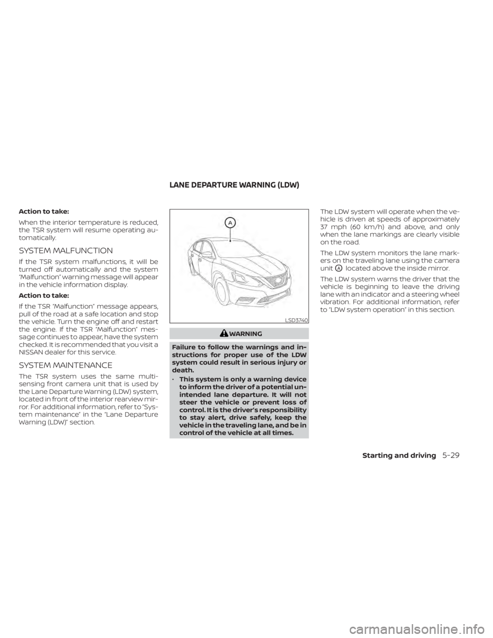
The LDW system monitors the lane mark-
ers on the traveling lane using the camera
unit
OAlocated above the inside mirror.
The LDW system warns the driver that the
vehicle is beginning to leave the driving
lane with an indicator and a steering wheel
vibration. For additional information, refer
to “LDW system operation” in this section.
LSD3740
LANE DEPARTURE WARNING (LDW)
Starting and driving5-29
Page 316 of 528
LDW SYSTEM OPERATION
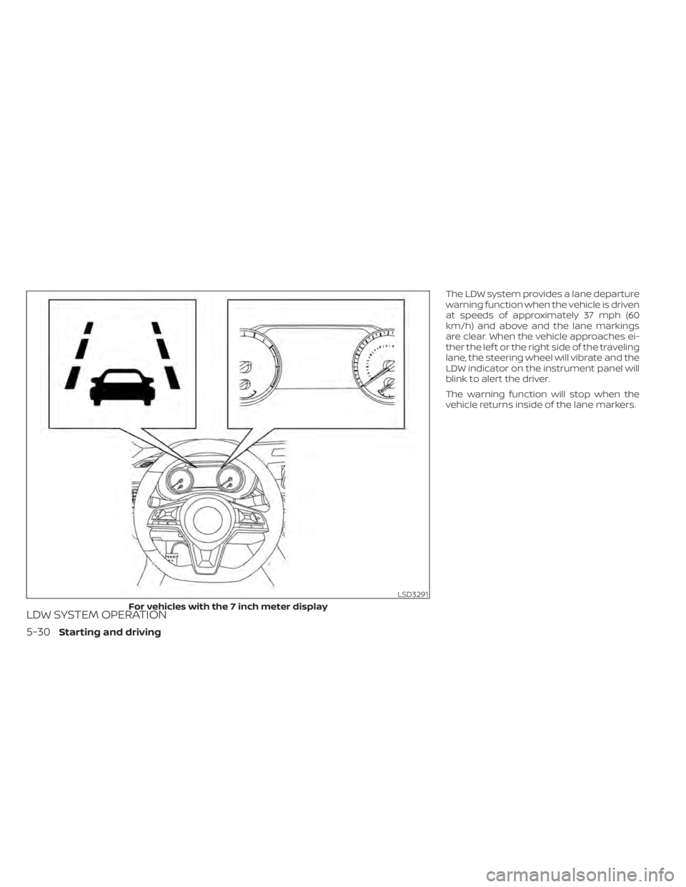
The LDW system provides a lane departure
warning function when the vehicle is driven
at speeds of approximately 37 mph (60
km/h) and above and the lane markings
are clear. When the vehicle approaches ei-
ther the lef t or the right side of the traveling
lane, the steering wheel will vibrate and the
LDW indicator on the instrument panel will
blink to alert the driver.
The warning function will stop when the
vehicle returns inside of the lane markers.
LSD3291
For vehicles with the 7 inch meter display
5-30Starting and driving
Page 320 of 528
•The system may not function prop-
erly under the following conditions:
– On roads where there are multiple
parallel lane markers; lane mark-
ers that are faded or not painted
clearly; yellow painted lane mark-
ers; non-standard lane markers;
or lane markers covered with wa-
ter, dirt, snow, etc.
– On roads where the discontinued
lane markers are still detectable.
– On roads where there are sharp
curves.
– On roads where there are sharply
contrasting objects, such as shad-
ows, snow, water, wheel ruts,
seams or lines remaining af ter
road repairs. (The LDW system
could detect these items as lane
markers.)
– On roads where the traveling lane
merges or separates.
– When the vehicle’s traveling direc-
tion does not align with the lane
marker.
– When traveling close to the ve-
hicle in front of you, which ob-
structs the lane camera unit de-
tection range. –
When rain, snow, dirt or an object
adheres to the windshield in front
of the lane camera unit.
– When the headlights are not
bright due to dirt on the lens or if
the aiming is not adjusted
properly.
– When strong light enters the lane
camera unit. (For example, the
light directly shines on the front of
the vehicle at sunrise or sunset.)
– When a sudden change in bright-
ness occurs. (For example, when
the vehicle enters or exits a tunnel
or under a bridge.)
SYSTEM TEMPORARILY
UNAVAILABLE
If the vehicle is parked in direct sunlight
under high temperature conditions (over
approximately 104°F [40°C]) and then
started, the LDW system may be deacti-
vated automatically and the following
message will appear in the vehicle infor-
mation display: “Unavailable: High Cabin
Temperature.”
When the interior temperature is reduced,
the LDW system will resume operating au-
tomatically. The LDW system is not designed to warn
under the following conditions:
• When you operate the lane change signal
and change traveling lanes in the direc-
tion of the signal. (The LDW system will
become operable again approximately 2
seconds af ter the lane change signal is
turned off.)
• When the vehicle speed lowers to less than approximately 37 mph (60 km/h).
Af ter the above conditions have finished
and the necessary operating conditions
are satisfied, the LDW functions will resume.
SYSTEM MALFUNCTION
If the LDW system malfunctions, it will can-
cel automatically and “Not Available Sys-
tem Malfunction” will appear in the vehicle
information display. If “Not Available Sys-
tem Malfunction” appears in the vehicle in-
formation display, pull off the road to a safe
location and stop the vehicle. Place the
shif t lever in the P (Park) position and the
ignition switch in the OFF position and re-
start the engine/motor. If “Not Available
System Malfunction” continues to appear
in the vehicle information display, have the
system checked. It is recommended that
you visit a NISSAN dealer for this service.
5-34Starting and driving
Page 326 of 528
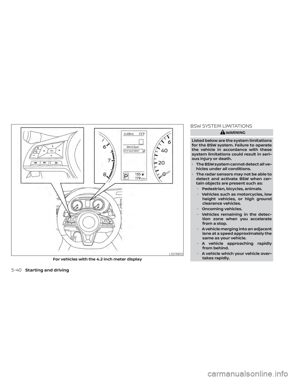
BSW SYSTEM LIMITATIONS
WARNING
Listed below are the system limitations
for the BSW system. Failure to operate
the vehicle in accordance with these
system limitations could result in seri-
ous injury or death.
• The BSW system cannot detect all ve-
hicles under all conditions.
• The radar sensors may not be able to
detect and activate BSW when cer-
tain objects are present such as:
– Pedestrian, bicycles, animals.
– Vehicles such as motorcycles, low
height vehicles, or high ground
clearance vehicles.
– Oncoming vehicles.
– Vehicles remaining in the detec-
tion zone when you accelerate
from a stop.
– A vehicle merging into an adjacent
lane at a speed approximately the
same as your vehicle.
– A vehicle approaching rapidly
from behind.
– A vehicle which your vehicle over-
takes rapidly.
LSD3805
For vehicles with the 4.2 inch meter display
5-40Starting and driving
Page 331 of 528
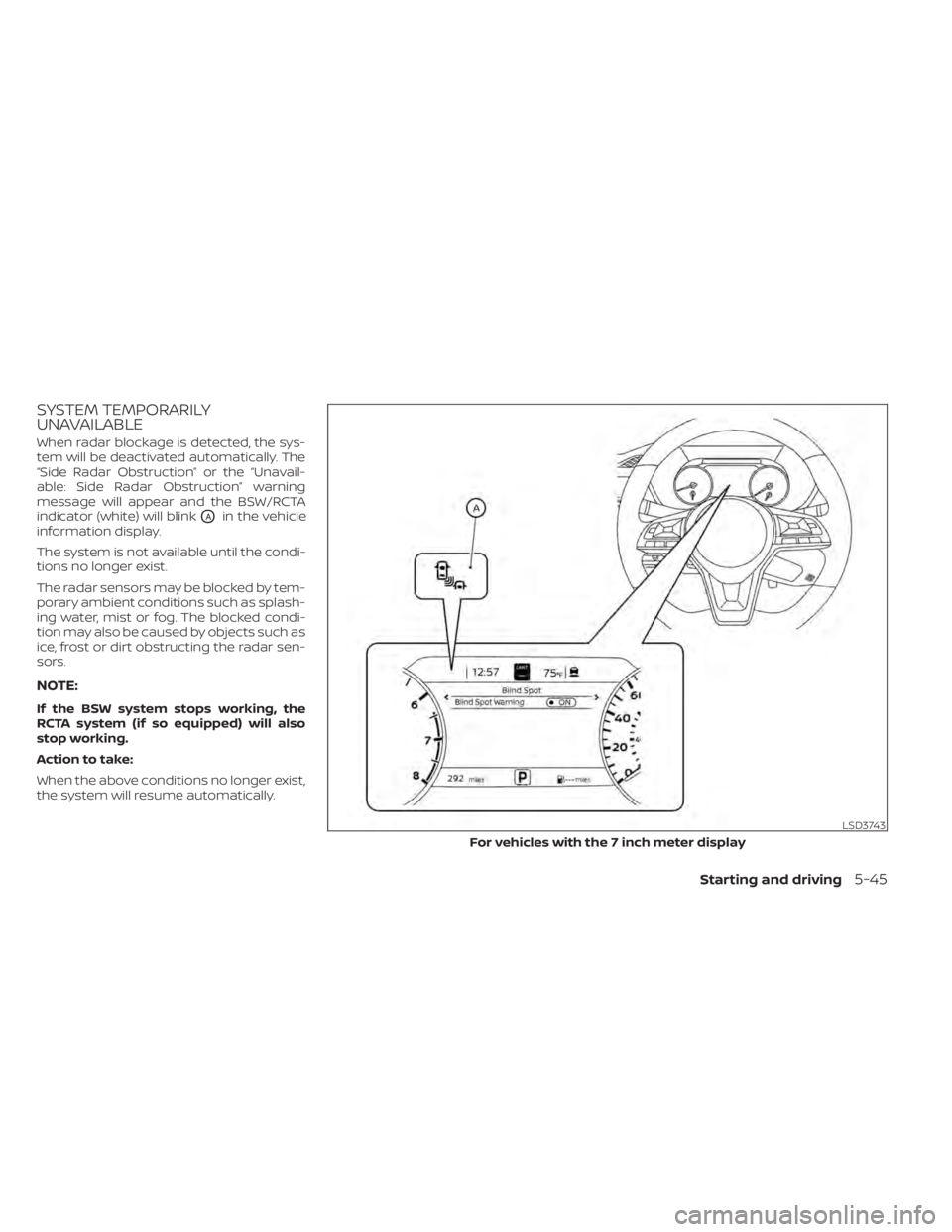
SYSTEM TEMPORARILY
UNAVAILABLE
When radar blockage is detected, the sys-
tem will be deactivated automatically. The
“Side Radar Obstruction” or the “Unavail-
able: Side Radar Obstruction” warning
message will appear and the BSW/RCTA
indicator (white) will blink
OAin the vehicle
information display.
The system is not available until the condi-
tions no longer exist.
The radar sensors may be blocked by tem-
porary ambient conditions such as splash-
ing water, mist or fog. The blocked condi-
tion may also be caused by objects such as
ice, frost or dirt obstructing the radar sen-
sors.
NOTE:
If the BSW system stops working, the
RCTA system (if so equipped) will also
stop working.
Action to take:
When the above conditions no longer exist,
the system will resume automatically.
LSD3743
For vehicles with the 7 inch meter display
Starting and driving5-45