NISSAN SERENA 1993 Service Repair Manual
Manufacturer: NISSAN, Model Year: 1993, Model line: SERENA, Model: NISSAN SERENA 1993Pages: 1254, PDF Size: 89.68 MB
Page 1151 of 1254

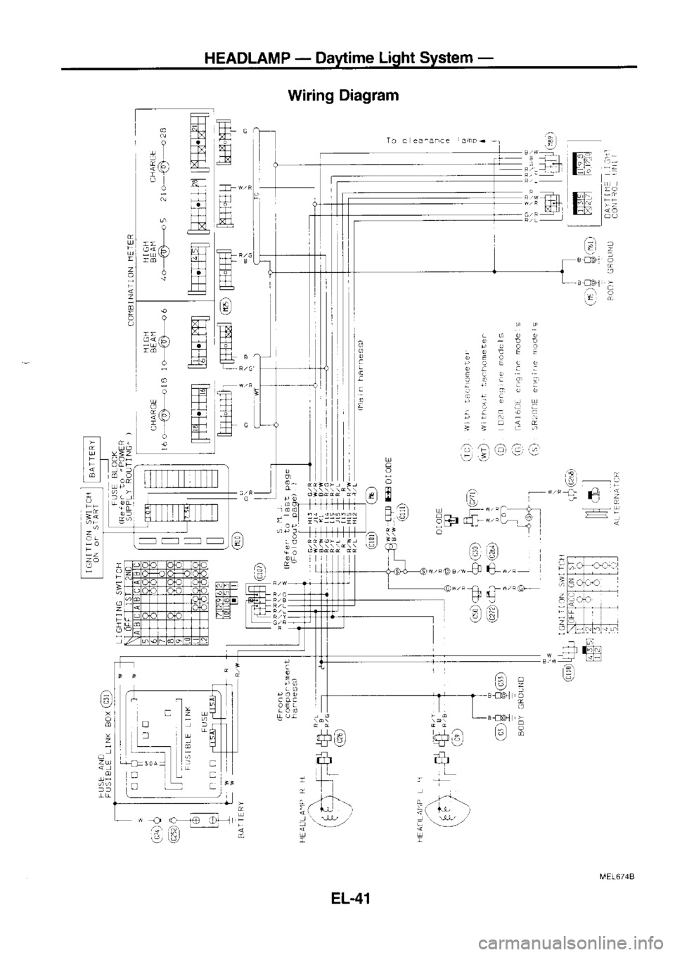
HEADLAMP
-
Daytime Light System -
Operation
After starting the engine with
lhe lighting
switch in the "OFF"
position, the headlamp low
beam and clearance,
tail, license
and instrumenl illumination
lamps automatically turn on. Light-
ing switch operations
other than the
above are the same
as
conventional light systems.
Engine Wjth engine stopped
Wrth engine running
Lighting switch OFF
1ST
2ND OFF 1ST
2ND
B c
Bc B
c B
c Bc B
c
Headlamp High
beam XX
o XX
o o Xo XX
o XX
oo X
o
LOW Deam XXX
Xx XX
o Xo
oo XX X
Xo X
Clearance and tail lamp X
XX
oo oo
o oo
ooo o
o ooo
License and instrument
illumination lamp X
X
Xo o
o oo
oo oo
oo o
oo o
O: Lamp "ON"
X: Lamp "OFF"
El: Added
functions
Schematic
] GNI TI ON SWI ICIl
ON o. START J
GN] T] ON SW] ICI
SIART BATTERY
a 7 9
5 tt
I
)? 3
OAYIIIlE L] GII
CON IROL
UN]T L]GNTING
SW] TCH
HEAO.
Rf. H]
GH AEAM
] NDI CAIOR
ALIERNAIOR LO2
0 ensine
mode s
Exccpt LDz0 eng ine
node s
MEL675A
EL4O
Page 1152 of 1254
HEADLAMP
-
Daytime Light
System -
Wiring Diagram
To. ea ^an.
e amF+
H
E
E
F
tr
TT
rq
t,t -F
H{
trTl
A
ffi fl
F?r
Tt l
E
ffi
zu
-n
ffi
q
C ir
ril
FE
!4
ffi
tTt
l-.l
r-
ffi
FF
H
-T-t
!:l:l
: 9
-l-
ttr
fT_
-T-
t
4c)
iY
i
Y
-u \Y/
z
o
z
E -..
Z
-
-.-
qr
E,i )
B!0!]
.a .a
o-"
l
a
c
o
5
E
til
- /:\
;; -
;
:
2
A
trT-l .4
L=
?
--J
;
i
:
---D
. .r
c- je-T"
t I
.tr' ,i'j -
A
,-D', [r_] ." 6lr6
Gr a,-
F:u /-L
I .G+
DLi
/a a.n
h:i
!:r €/
6), -
reJc
t
/:\
L€/
I
;
I rEl
5 Frl
t-,
eml -
eH
qF,3l
-n rtr
-i
=
+so
ffi'
fl
,--]---.: t-*,-'
I
i
T
zu -----1
o
3- rR."i
al
t,
o =l
n o rldadd
dd
t!.4E16744
EL.41
Page 1153 of 1254
HEADLAMP
-
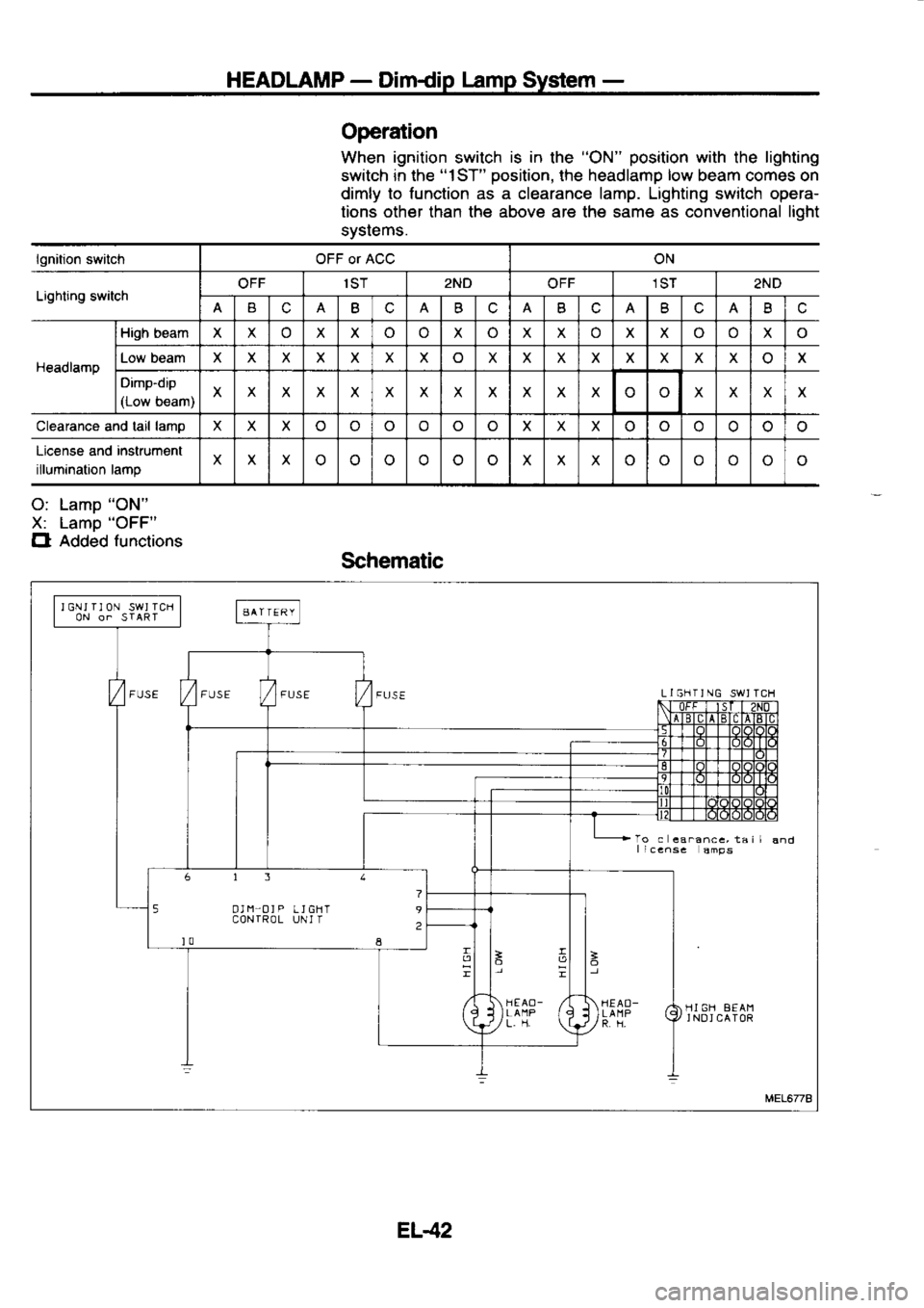
Dimdip lamp
System -
Operation
When ignition
switch is
in
the "ON" position
with the lighting
switch in the "1ST"
oosition. the headlamo low
beam comes on
dimly to
function as a clearance lamp. Lighting switch opera-
tions other than the above are the same as conventional fioht
svstems.
lgnition switch OFF or ACC ON
Lighting switch OFF
1ST
2ND
OFF 1ST
2ND
B c B Bc Bc B(.
Bc
Headlamp High
beam XXo Xxo Xo XX XX
o X
Low beam X
X XX
X X
Xo XX XX XXX x
o X
Dimp-dip
(Low b€am) X
x XXX XXXX Xx X xXXX
Clearance and tail lamo
Xx X
o o XX X
oo o
License and instrument
illumination lamp X
Xx
o oXX X o o
o
O: Lamo "ON"
X: Lamo "OFF"
Cl Added
functions
Schematic
I GNJ I]
ON SWJ ICH
0N o. START AAITERY
5 O] I1'O]
P
LJGHT 9
CON IROL UNI I
?
it
]? L]GIlT]NG
SWJ TCH
To c
€a.ance, ta i I
I iccnse
amps
HI GH 8EAI1
J NO]
CAIOR
MEL6/78
EL42
Page 1154 of 1254
![NISSAN SERENA 1993 Service Repair Manual HEADLAMP
-
Dimdip lamp
System -
Wiring Diagram
rn
\y
!t- -T-.1-.1|
Tr]
Tr"l
ffi T5-1
m
E (€J
:
6,3
r_rejt =
LZ
OO
R |l
|]
tl
6- euJJg@
tq
d );)))d)d;,i /l
p6 ,, i i trl
u or- NISSAN SERENA 1993 Service Repair Manual HEADLAMP
-
Dimdip lamp
System -
Wiring Diagram
rn
\y
!t- -T-.1-.1|
Tr]
Tr"l
ffi T5-1
m
E (€J
:
6,3
r_rejt =
LZ
OO
R |l
|]
tl
6- euJJg@
tq
d );)))d)d;,i /l
p6 ,, i i trl
u or-](/img/5/57387/w960_57387-1153.png)
HEADLAMP
-
Dimdip lamp
System -
Wiring Diagram
rn
\y
!'t- -T-.1-.1|
Tr]
Tr"l
ffi T5-1
m
E (€J
:
6,3
r_re'jt =
LZ
OO
R |l
|]
tl
6- euJJ'g@
tq
d );)))d)d;,i /l
p6 ,', i' 'i trl
u or----f-t-l-t-t- v
a66l
-- ol
:l:9dc9{,!
L_ | rr4---t i--
-;:+H++++H+a
bl tr<<:ir"li (7
dc rrrrrlrrri LG,S_
F. s -Gll
H +fm
:J^-r
-----6-d-:',P
^l
/ax I
Lti 19 co
f$a
t?T
/'\
\9
EEE tffi-
mJ r+Ft
ffi llE
L::
c
E
cc
I!r
OE
9a
6t,
;;
(t tt ;)j
t_i.Iri
tu..r,! ta i ttl_\
lm aj 6\-
6t,'F
@ll,: (9 co
tcn tcD
- |i - l|
; Til :
t.rl
t.frh t.trh
6 U'
,/ 6
U-,l
,/
II
:}<
MEL676A
Page 1155 of 1254
HEADLAMP
-
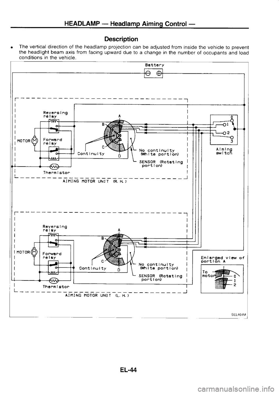
Headlamp Aiming
Control-
Description
o The
vertical direction
of the headlamp prolection
can be adjusted
lrom inside the vehicle
to prevent
lhe headlight beam
axis from
facing upward
due to a change
in the number of
occupants and load
conditions in
the vehicle.
Battot^y
En I
a.ocd
gont l6n A
Rcvc
na In9
t cIlv
Cont Inu lty
Fon
/ard
.e lay
Almlno
gw I tc6
No cont Inu lty
(Wh lt6 po.t
lor,
SENS0R (Rotat
Ino
po.t I od
No
cont Inu lty
(Wh ltc po.t
I or,
SENSOR (RotEt
Ina
por-t I od
I Thoi. trto.
AI I1I NG I1OTOR
UNI T (R.
I-t )
Rcve.a Ino
rc l!y
Cont lnu lty
Jhc nn I
ator
AI MI NG I'IOTOR
UNI T (L.
I{ )
EL-44
Page 1156 of 1254
![NISSAN SERENA 1993 Service Repair Manual HEADLAMP
-
Headlamp Aiming Control-
Description (Contd)
lJp and down adjustrng screw
Armrng motor untt
CIRCUIT OPERATION
IExample]
Aiming switch "0"
o When
the aiming switch rs set to " NISSAN SERENA 1993 Service Repair Manual HEADLAMP
-
Headlamp Aiming Control-
Description (Contd)
lJp and down adjustrng screw
Armrng motor untt
CIRCUIT OPERATION
IExample]
Aiming switch "0"
o When
the aiming switch rs set to "](/img/5/57387/w960_57387-1155.png)
HEADLAMP
-
Headlamp Aiming Control-
Description (Cont'd)
lJp and down adjustrng screw
Armrng motor untt
CIRCUIT OPERATION
IExample]
Aiming switch "0"
o When
the aiming switch rs set to "0",
the motor will not
start
because the power
terminals are positioned
at the noncon-
ductive section ol lhe sensor's rotarv
unit.
0 l
2 3 Aiming
switch "O" --
"1"
o When
the aiming switchis moved from "0"
to "1",
power is
applied to the motor through the relay
operated by the
sensor's conductive secton. The
headlamps
will then move
in lhe "DOWN"
direction.
o The
motor continues lo rotate while the rotary unit
of the
sensors moves from point
A to point
B.
o The power
terminals will
lhen be positioned
at the noncon-
ductive seclion, disconnecting the power
tothe motor.
The
motor lhen slops.
Aiming switch "1"
-
"0"
o When
the aiming switch is moved from "1"
to "0",
power
ts
applied to the motor through
the relay
operated by the
conductive section of the
sensor. The
motor
will rotate to
move the headlamps in
the "UP"
direction.
o When
the rotary
unit of the sensor moves from point
B to
point A, the motor
will
stop.
EL-rts
Page 1157 of 1254
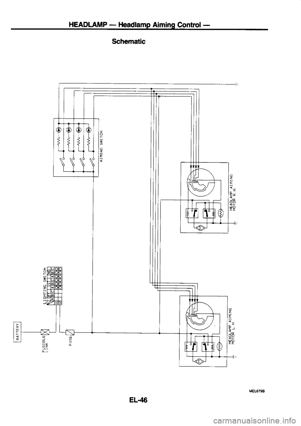
HEADLAMP
-
Headlamp Aiming Control-
EL.45
Page 1158 of 1254
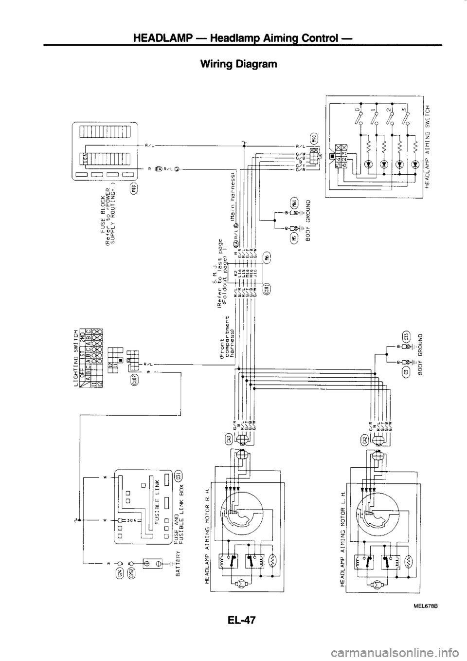
HEADLAMP
-
Headlamp Aiming
Control-
/:\6
o *#l
e -{-rl
Wiring
Diagram
,a I )'+t' I
\? *'Ha
l
c
E^
f oc
---t-
^/A
€lo
=
o
zu
n
:
Lrn
-Ll
6
i; L-l
tr
o
!
.
a
!
-
EL47
Page 1159 of 1254
HEADLAMP
-
Headlamp Aiming
Control-
A Cil
Lighting swrlch lsl
5r
ts EI'H)
mtri
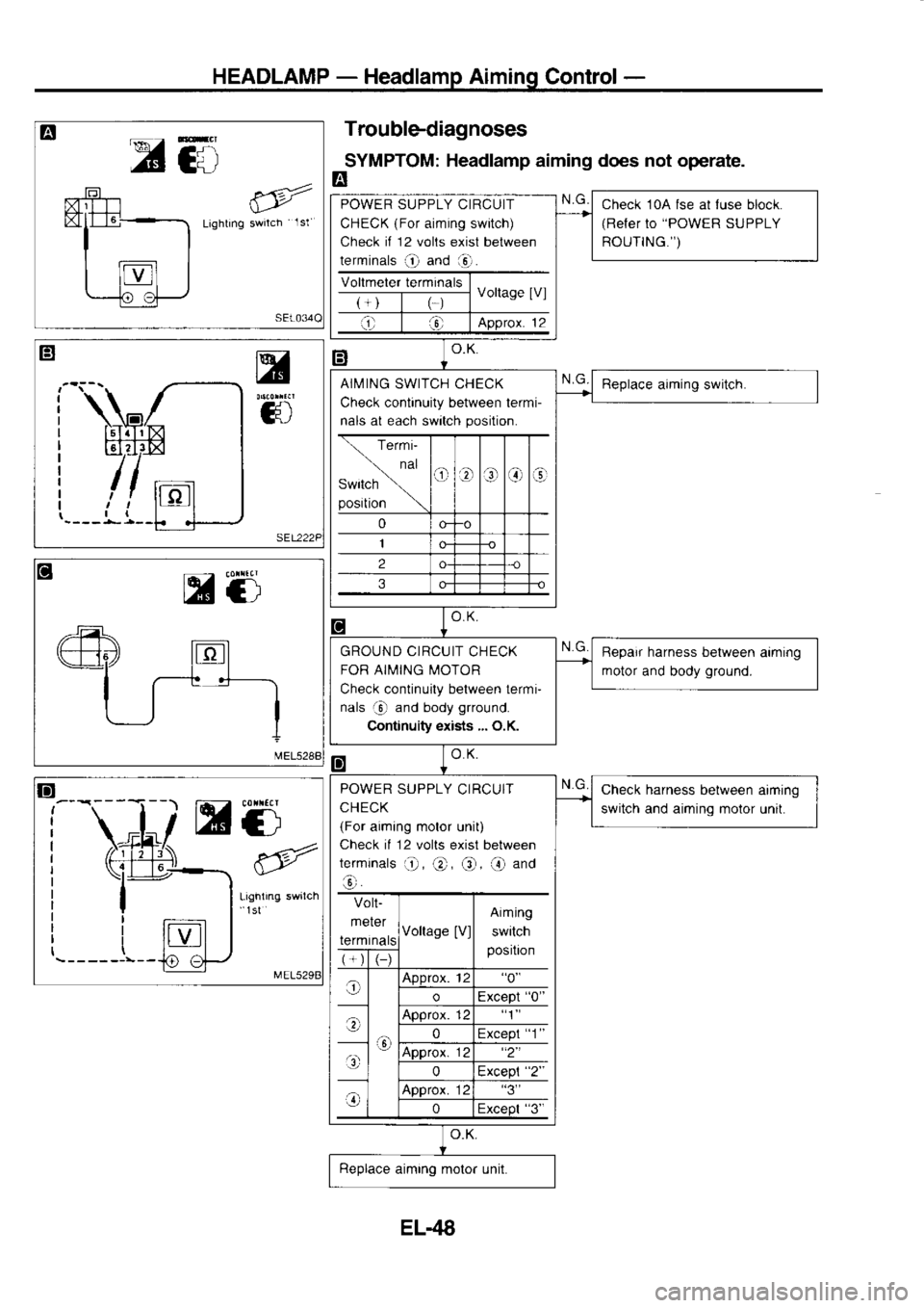
mti Troublediagnoses
SYMPTOM: Headlamp
aiming does not operate.
E
Check 10A fse
al luse
block.
(Refer to "POWER
SUPPLY
ROUTING.")
POWER
SUPPLY CIRCUIT
CHECK (For
aiming switch)
Check if
12 volts
exist between
terminals O and
aO.
AIMING SWITCH CHECK
Check continuity between termi-
nals at each switch position.
GROUND CIRCUIT
CHECK
FOR AIMING MOTOR
Check continuity between termi-
nals rj)
and body grround.
Continuity exists ... O.K. Bepair
harness between
aiming
motor and body ground.
POWER SUPPLY CIRCUIT
CHECK
(For aiming motor unit)
Check il 12 volts
exist between
terminats 'O,
@, @, @ and
o Volt-
meter
termina Voltage
[V]Aiming
switch
posrtron
o Approx.
12"0"
o "0"
.;\ Approx.
12"1"
0 "1"
o Approx.
12
0
o Approx.
12,.3,,
0 "3"Check
harness
between aimjng
switch and aiming motor
unit.
EL.48
Page 1160 of 1254
HEADLAMP
PUSH Io
\
_@. PUSH
lo Bulb
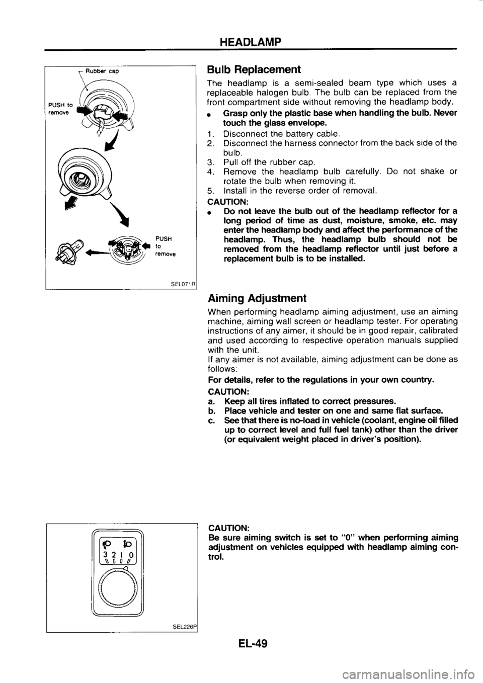
Replacement
The headlamp is
a semi-sealed beam type which
uses a
replaceable halogen
bulb. The
bulb can
be replaced from
the
f ront compartment side without
removing the headlamp
body.
r Grasp
only the plastic
base when
handling the bulb.
Never
touch the glass
envelope.
1. Disconnect the
battery cable.
2. Disconnect the
harness connector from
the back side ol the
bulb.
3. Pull
off the
rubber cap.
4. Remove the headlamp
bulb carefully. Do
not shake or
rotate the bulb when removing it.
5. Install
in the reverse
order of removal.
CAUTION:
o Do
not leave the bulb out of the headlamp
reflector for a
long period
of time as dust, moisture,
smoke, etc. may
enter the headlamp
body and aflect the pedormance
of the
headlamp. Thus, the headlamp
bulb should not
be
removed from
the headlamp reflector until just
before a
replac€ment bulb is
to be installed.
Aiming Adjustment
When performing
headlamp aiming adjustment, use
an aiming
machine, aiming wall screen or headlamp
lester. For
operating
instructions of any aimer, it should be in good
repair, calibrated
and used according to
respective operation manuals
supplied
with the unit.
lf any aimer is
not available, aiming adjustment can be done as
Iollows:
For details, reter
to the regulations in your
own country.
CAUTION:
a. Keep all tires inflated to correcl pressures.
b. Place vehicle
and tester on one
and same flat surface-
c. See that there
is noload in vehicle (coolant,
engine oil filled
up to correct level
and tull tuel tank) other than the driver
(or equivalent weight placed
in driver's position).
CAUTION: Be sure aiming switch
is set to "0"
when performing
aiming
adiustment on
vehicles equipped with
headlamp
aiming con-
trol.
lF-bl
l3 2
I 0l
L,\_-! S l l
,n
[) \/
EL-49